
Related Manuals for Raven SBGUIDANCE SMARTRAX MD


Summary of Contents for Raven SBGUIDANCE SMARTRAX MD
- Page 1 SBGUIDANCE SMARTRAX MD 016-8000-098EN REV. A Installation manual (English) (Original)
- Page 2 Raven Industries Inc. PAGINA 2/48 | Installation manual | 016-8000-098EN | Rev. A...
-
Page 3: Preface
Any comments or questions can be sent to service- should take note of. eu@ravenind.com. Caution!: Raven Europe or any of its suppliers will accept no Indicates that the machine can be damaged. liability for physical or material damage caused whilst using the SBGuidance system. Warning!: Indicates a risk of injury. -
Page 4: Disclaimer
This will extend the life span of the electronic components. To prevent theft, it is better to not let the terminal and GPS-antenna unattended in the tractor on the field. Raven Industries Inc. PAGINA 4/48 | Installation manual | 016-8000-098EN | Rev. A... -
Page 5: Table Of Contents
4.2 MOUNTING OF BRAND-DEPENDENT GPS ANTENNA BRACKET ................26 4.3 MOUNTING ONE’S OWN DESIGN OF GPS ANTENNA BRACKET ................26 4.4 MOUNTING RAVEN 600S ANTENNA ........................... 27 4.5 MOUNTING THE RADIO ANTENNA ............................28 4.6 MOUNTING THE GPRS/UMTS ANTENNA ........................... 29 4.7 MOUNTING GPS PATCH ANTENNA ............................. - Page 6 CONTENT | SBGUIDANCE | SMARTRAX MD Raven Industries Inc. PAGINA 6/48 | Installation manual | 016-8000-098EN | Rev. A...
-
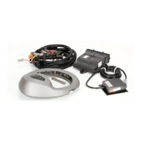
Page 7: Kit Contents
This section contains a list of the components that are included in the SmarTrax kit. Before beginning the SmarTrax installation, compare the items in the kit with the components on this list. If you have questions about the kit, contact your Raven dealer. TABLE 1 OVERVIEW OF STANDARD ELECTRONICAL COMPONENTS... - Page 8 MOUNT, 1" RAIL, RAM D 11078000072 BRACKET, WAS, AXLE 11078000071 BRACKET, WAS, STRIP 11178000341 KIT, MOUNTING, TRACTOR Tip!: The provided mounting kit 11178000341 contains all fasteners for the components. Raven Industries Inc. PAGINA 8/48 | Installation manual | 016-8000-098EN | Rev. A...
- Page 9 KIT CONTENTS | SBGUIDANCE | SMARTRAX MD TABLE 3 OVERVIEW OF MAKE OR TYPE SPECIFIC MECHANICAL COMPONENTS PART NUMBER ITEM DESCRIPTION 11078000121 CNH – GPS-ANTENNA BRACKET (T6000, T7000, T6, T7 EN CASE MAXXUM/PUMA) 11078000070 FENDT SCR RAM BRACKET (VISIO PLUS CAB, 500 EN 700- SCR SERIES) 11078000069 FENDT RAM BRACKET (FENDT VARIO 400, 700, 800 EN 900-...
- Page 10 KIT CONTENTS | SBGUIDANCE | SMARTRAX MD Intentionally left blank. Raven Industries Inc. PAGINA 10/48 | Installation manual | 016-8000-098EN | Rev. A...
-
Page 11: Tractor Set Assembly
TRACTOR SET ASSEMBLY | SBGUIDANCE | SMARTRAX MD 1 TRACTOR SET ASSEMBLY It is recommended to assemble the tractor set in the following order: 1. Mount the entire wiring harness from the battery and steering controller. 2. Mount the wheel angle sensor and cable. 3. - Page 12 TRACTOR SET ASSEMBLY | SBGUIDANCE | SMARTRAX MD Intentionally left blank. Raven Industries Inc. PAGINA 12/48 | Installation manual | 016-8000-098EN | Rev. A...
-
Page 13: Mounting The Wiring Harness
2 MOUNTING THE WIRING HARNESS The total SBGuidance cable harness exist of several cables, from the battery to the terminal. Raven Europe offers two power harness options; the CAN Basic harness or the Implement Ready (IR) harness. As an in- cab terminal harness Raven Europe offers a harness to connect the Viper 4(+) or the older GeoStar terminal. -
Page 14: Installing The Cable Harnesses
(DynamIQ ISO) to the terminal. The terminal harness is connected with two connectors to the in-cab harness (DynamIQ ISO). When using a Raven 600S GPS receiver, the 600S harness is connected to the terminal harness too (see Figure 50). - Page 15 MOUNTING THE WIRING HARNESS | SBGUIDANCE | SMARTRAX MD In addition, a number of guidelines have been established for the assembly of both types of cable harnesses: Mount the relays fixed and in a dry, clean and accessible spot (Figure 3). The red wire is + (12V).
-
Page 16: Mounting Wheel Angle Sensor
‘spy cable’ is available at Raven Europe to use the factory fitted wheel angle sensor for the Raven system. When a spy cable is used it is not necessary to install a wheel angle sensor. Ask Raven Europe for more information about the availability for a specific tractor brand or type. -
Page 17: Mounting The Wheel Angle Sensor
MOUNTING WHEEL ANGLE SENSOR | SBGUIDANCE | SMARTRAX MD 3.2 MOUNTING THE WHEEL ANGLE SENSOR Figure 5 and Figure 6 show a detailed view of the structure of a wheel angle sensor assembly. Table 5 also lists the components shown in Figure 5. TABLE 5 WHEEL ANGLE SENSOR COMPONENTS. - Page 18 (stub axle/pivot point) of the front axle so that the wire is not pinched or constricted. FIGURE 9 STUB AXLE WITH GREASE NIPPLE. Raven Industries Inc. PAGINA 18/48 | Installation manual | 016-8000-098EN | Rev. A...
-
Page 19: Mounting The Sensor Disc
MOUNTING WHEEL ANGLE SENSOR | SBGUIDANCE | SMARTRAX MD 3.2.2 MOUNTING THE SENSOR DISC Mount the sensor disc without spacers on the provided 20x3 strip (Figure 10). Mount the sensor disc in the sensor housing and mark where the first bend should be made (about 10 cm from the beginning). - Page 20 (Figure 14). Also turn the wheels to make sure the sensor housing remains properly centered in various wheel positions. FIGURE 14 DISC AT THE OTHER SIDE OF THE STRIP. Raven Industries Inc. PAGINA 20/48 | Installation manual | 016-8000-098EN | Rev. A...
- Page 21 MOUNTING WHEEL ANGLE SENSOR | SBGUIDANCE | SMARTRAX MD 14. Remove the strip again from the front axle. Then mount the strip again to the front axle with the aid of M5 X 30 bolts, raised with two nuts and two washers on each side. Mount on the proper side of the strip (Figure 15) and pay attention to the orientation of the disc (Figure 7).
- Page 22 Cleaning the wheel angle sensor magnet with compressed air can prevent problems. FIGURE 18 CENTRE AND FRICTION CHECK OF WHEEL ANGLE SENSOR. FIGURE 19 CORRECT MOUNTED WHEEL ANGLE SENSOR. Raven Industries Inc. PAGINA 22/48 | Installation manual | 016-8000-098EN | Rev. A...
-
Page 23: Heavy-Duty Carraro Front Axle With Independent Suspension
MOUNTING WHEEL ANGLE SENSOR | SBGUIDANCE | SMARTRAX MD 3.3 HEAVY-DUTY CARRARO FRONT AXLE WITH INDEPENDENT SUSPENSION Tractors with the heaviest type of Carraro front axle with independent suspension must be fitted with a special wheel angle sensor bracket (Figure 20). This type of assembly requires a wheel angle sensor with a much wider range (180°) in connection with the larger wheel turn (blue coloured wheel angle sensor). -
Page 24: Mounting Gps And Radio/Gsm Antenna
Label all the antenna cables with the correct label. This makes it easier for the operator, to connect the antennas to the correct connections on the modem and GPS terminal. FIGURE 23 RAVEN 600S GPS-ANTENNA. Raven Industries Inc. PAGINA 24/48 | Installation manual | 016-8000-098EN | Rev. A... -
Page 25: Mounting The Standard Gps Antenna Bracket
MOUNTING GPS AND RADIO/GSM ANTENNA | SBGUIDANCE | SMARTRAX MD MOUNTING THE STANDARD GPS ANTENNA BRACKET Figure 24 shows an example of the structure of standard GPS antenna equipment, which consists of a standard GPS antenna bracket, a GPS dummy and an UNC bolt + nut. -
Page 26: Mounting Of Brand-Dependent Gps Antenna Bracket
MOUNTING GPS AND RADIO/GSM ANTENNA | SBGUIDANCE | SMARTRAX MD MOUNTING OF BRAND-DEPENDENT GPS ANTENNA BRACKET If appropriate and available (check availability at Raven Europe!) a specific brand of GPS antenna bracket can be used. The same guidelines as described in section 4.1 apply to the installation. -
Page 27: Mounting Raven 600S Antenna
4.4 MOUNTING RAVEN 600S ANTENNA It is also possible to use SBGuidance Auto in combination with a Raven 600S antenna (Figure 25). In this manual the installation of the 600S antenna is explained. For the configuration of this antenna see the English configuration manual: ‘016-8000-025EN-A... -
Page 28: Mounting The Radio Antenna
GPS antenna bracket). A larger steel base surface can improve signal strength and prevent problems, especially at greater distances (> 9 km). Label the antenna cable inside the cabin with label ‘Radio’. Raven Industries Inc. PAGINA 28/48 | Installation manual | 016-8000-098EN | Rev. A... -
Page 29: Mounting The Gprs/Umts Antenna
| SBGUIDANCE | SMARTRAX MD MOUNTING THE GPRS/UMTS ANTENNA If a SlingShot modem is used, in addition to the GPS- antenna, two GPRS / UMTS antennas and a GPS patch should be mounted. FIGURE 32 GPS ANTENNA BRACKET WITH A LAIRD UMTS ANTENNA. -
Page 30: Mounting Dynamiq Iso And Stu
FIGURE 33 DYNAMIQ ISO AND STU MOUNTED pointing towards the rear (as shown in Figure NEXT TO THE SEAT. 33). Any other orientation should be set in the software! Raven Industries Inc. PAGINA 30/48 | Installation manual | 016-8000-098EN | Rev. A... - Page 31 MOUNTING DYNAMIQ ISO AND STU | SBGUIDANCE | SMARTRAX MD Intentionally left blank. PAGINA 31/48 | Installation manual | 016-8000-098EN | Rev. A...
-
Page 32: Mounting Mechanical Drive Unit
FIGURE 34 MECHANICAL DRIVE UNIT right manual (Figure 35). If there is no manual available for the tractor you want to install SmarTrax MD please contact Raven Europe. FIGURE 35 PORTAL RAVEN PRECISION Raven Industries Inc. PAGINA 32/48 | Installation manual | 016-8000-098EN | Rev. A... - Page 33 MOUNTING MECHANICAL DRIVE UNIT | SBGUIDANCE | SMARTRAX MD PAGINA 33/48 | Installation manual | 016-8000-098EN | Rev. A...
-
Page 34: Mounting The Terminal
FIGURE 37 GEOSTAR TERMINAL MOUNTED TO ISO ATTACHMENT OF A-PILLAR. Raven Industries Inc. PAGINA 34/48 | Installation manual | 016-8000-098EN | Rev. A... - Page 35 MOUNTING THE TERMINAL | SBGUIDANCE | SMARTRAX MD Intentionally left blank. PAGINA 35/48 | Installation manual | 016-8000-098EN | Rev. A...
-
Page 36: Calibration
– SBGuidance Auto – CAN – EN (016-8000-100EN-A). However, some settings in the CANtool are different. The different parts of configuring a tractor with SBGuidance Smartrax MD are described in this chapter. CANTOOL Start the Configurator (by pressing “Shift + SBGuidance’’... -
Page 37: Check Firmware Versions
CALIBRATION | SBGUIDANCE | SMARTRAX MD Go to tab MyDevice (Figure 40) and select at Pre- selection ‘’Navigation Controller (tractor)’’. Select at Type ‘’SBGuidance’’. Push the Connect button. CHECK FIRMWARE VERSIONS The Steering Controller (STU) is the module that controls the Smartrax MD steering motor and reads in the wheel angle sensor value and the pressure sensor value. -
Page 38: Steering
If one of these values shows 0,00V, do not proceed with the calibration procedure and first fix the underlying issue (check fuses, relays, cabling etc.). FIGURE 43 BOARD STATUS TAB. Raven Industries Inc. PAGINA 38/48 | Installation manual | 016-8000-098EN | Rev. A... -
Page 39: Wheel Sensor
CALIBRATION | SBGUIDANCE | SMARTRAX MD WHEEL SENSOR Go to the tab Wheel Sensor (Figure 44). Turn the wheels of the machine completely to the left. Press the button beneath “Left”, to set the outer left limit of the wheel angle sensor. Turn the wheels of the machine completely to the right. -
Page 40: Steer Sensor
Press Save after the calibration is done or after the disengage sensitivity is changed. FIGURE 45 CALIBRATING DISENGAGE SENSOR Raven Industries Inc. PAGINA 40/48 | Installation manual | 016-8000-098EN | Rev. A... -
Page 41: Pid Steer
CALIBRATION | SBGUIDANCE | SMARTRAX MD 8.7 PID STEER Open the PID Steer tab (Figure 46) to optimize PID controller settings. The settings on this tab influence the aggressiveness of the steering system. Always tune the “Proportional Gain” and leave the “Dealer Gain” at 100%! 1. -
Page 42: Manual Steering
(red line is no longer visible at that point). Make sure all the other steps in calibrating a tractor (Manual 016-8000-100EN-A) are completed! Raven Industries Inc. PAGINA 42/48 | Installation manual | 016-8000-098EN | Rev. A... - Page 43 CALIBRATION | SBGUIDANCE | SMARTRAX MD Intentionally left blank. PAGINA 43/48 | Installation manual | 016-8000-098EN | Rev. A...
-
Page 44: Annexes
Actuator power ECU power N.C. N.C. N.C. N.C. CAN High Yellow CAN Low Green N.C. N.C. N.C. N.C. ECU ground Black Actuator ground Black Actuator ground Black Raven Industries Inc. PAGINA 44/48 | Installation manual | 016-8000-098EN | Rev. A... -
Page 45: Schematic Overview Basic Harness
ANNEXES | SBGUIDANCE | SMARTRAX MD SCHEMATIC OVERVIEW BASIC HARNESS FIGURE 48 SYSTEM OVERVIEW PAGINA 45/48 | Installation manual | 016-8000-098EN | Rev. A... -
Page 46: Schematic Overview Implement Ready
ANNEXES | SBGUIDANCE | SMARTRAX MD SCHEMATIC OVERVIEW IMPLEMENT READY FIGURE 49 SYSTEM OVERVIEW IMPLEMENT READY Raven Industries Inc. PAGINA 46/48 | Installation manual | 016-8000-098EN | Rev. A... -
Page 47: Mounting 600S Gps-Antenna
ANNEXES | SBGUIDANCE | SMARTRAX MD MOUNTING 600S GPS-ANTENNA Afbeelding uitlijnen met tekst. Tekst van kolom uitlijnen op rechts. Breedte afbeelding 80 m Rechtermuisknop invoegen bijschrift FIGURE 50 MOUNTING 600S ANTENNA. PAGINA 47/48 | Installation manual | 016-8000-098EN | Rev. A... - Page 48 Hoornseweg 22 1775 RB, Middenmeer The Netherlands Phone: +31 227 54 93 00 Web: www.raveneurope.com Email: service-eu@ravenind.com...
Need help?
Do you have a question about the SBGUIDANCE SMARTRAX MD and is the answer not in the manual?
Questions and answers