
Related Manuals for OBO Bettermann PYROLINE Rapid

Summary of Contents for OBO Bettermann PYROLINE Rapid
- Page 1 PYROLINE Rapid fire protection duct ® Mounting instructions Building Connections 11/2019 EN...
- Page 2 PYROLINE Rapid fire protection duct ® Mounting instructions © 2019 OBO Holding GmbH & Co. KG Bettermann Reprinting, even of extracts, as well as photographic or electronic reproduction are prohibited!
-
Page 3: Table Of Contents
Table of contents Table of contents About these instructions Target group ....... 5 Using these instructions . - Page 4 Disposal after a fire ......78 Technical data Appendix – declaration of conformity (sample) 4 | EN OBO Bettermann...
-
Page 5: About These Instructions
About these instructions About these instructions Target group These instructions are aimed at trained installation engineers as well as those people trained in fire protection. Using these instructions • Before commencing work, read these instructions through once com- pletely. In particular, please observe the safety instructions. •... -
Page 6: Applicable Documents
Recommended documents – Fire protection guide for electrical installations (published by: OBO Bettermann). – LFS system instructions (published by: OBO Bettermann). General safety information When handling the product, please observe the following safety informa- tion, in order to avoid damage to people and property: The maximum approved total load is 30 kg per running duct metre. -
Page 7: Product Description
Product description Product description Properties/functional method The OBO fire protection duct system PYROLINE® Rapid is a closed installation duct system, which, if there is a fire, contributes to the pro- tection of the environment through the intumescence of the internal fire protection coating. -
Page 8: Overview Of Mounting Types
With direct mounting, ducts and fittings are screwed directly to the fasten- ing substrate. See also “5 Direct mounting on the ceiling, wall or floor” on page 22. Fig 1: Direct mounting on the wall and ceiling Fig 2: Direct mounting in the system base 8 | EN OBO Bettermann... -
Page 9: Fastening Base
Product description When mounted on a support system, ducts are screwed to support profiles and fittings using the appropriate lock plates. In turn, these are fastened to the ceiling using threaded rods. See also “6 Mounting on a support system” on page 38. Fig 3: Suspended mounting on a support system Fastening base The fastening substrate of PYROLINE... -
Page 10: System Overview
14 T reducing branch piece BSKM-TRK 1025 (7216467/7216648) 15 T reducing branch piece BSKM-TR 1025 (7216466/7216647) 16 90° flat angle BSKM-FW 1025 (7216430/7216638) 17 End piece BSKM-VK 1025 (7216460/7216644) 18 Foam seal (cable exit) BSKM-KA 1025 (7216490) 10 | EN OBO Bettermann... -
Page 11: Duct Width 110 Mm, Direct Mounting
Product description 3 6 2 Duct width 110 mm, direct mounting Fig 5: System overview, 110 mm duct width, direct mounting 1 Fire protection duct BSKM 0711 (7216300/7216600), with lid 2 Duct connector BSKM-VD 0711 (7216310/7216601) 3 Duct connector for corner mounting BSKM-VE 0711 (7216312/7216312) 4 Cable clamp for wall mounting BSKM-BW 0711 (7216370) 5 Self-tapping screw BSKM-S 4008 (3498092) -
Page 12: Duct Width 70 Mm, Direct Mounting
10 End piece BSKM-VK 0407 (7216560/7216561) 11 T reducing branch piece BSKM-TRK 1025 (7216467/7216648) 12 T reducing branch piece BSKM-TR 0711 (7216366/7216616) 13 90° flat angle BSKM-FW 0407 (7216524/7216506) 14 Foam seal (cable exit) BSKM-KA 0407 (7216590) 12 | EN OBO Bettermann... -
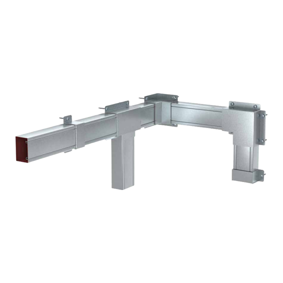
Page 13: Duct Width 250 Mm, Mounting On Support System
Product description 3 6 4 Duct width 250 mm, mounting on support system Fig 7: System overview, duct width 250 mm, mounting on support system 1 Fire protection duct BSKM 1025 (7216400/7216630) 2 90° flat angle BSKM-FW 1025 (7216430/7216638) with lock plate BSKM-GF 1025 (7216435/7216639) 3 90°... - Page 14 Product description 14 Support plate BSKM-AD 1025 (7216415/7216635) with duct connector BSKM-VD 1025 (7216410/7216633) Not shown: Locking bracket RKV3V, self-tapping screw BSKM-S 4008 and foam seal BSKM-KA 1025 (see Fig. 4 on page 10). 14 | EN OBO Bettermann...
-
Page 15: Duct Width 110 Mm, Mounting On Support System
Product description 3 6 5 Duct width 110 mm, mounting on support system Fig 8: System overview, duct width 110 mm, mounting on support system 1 Fire protection duct BSKM 0711 (7216300/7216600) 2 90° internal corner BSKM-IE 0711 (7216340/7216608) with lock plate BSKM-GI 0711 (7216345/7216609) 3 90°... -
Page 16: Duct Width 70 Mm, Mounting On Support System
BSKM-GI 0407 (721630/7216509) 10 Support plate BSKM-AD 0407 (7216515/7216516) with duct connector BSKM-VD 0407 (7216510/7216511) Not shown: Locking bracket RKV3V, self-tapping screw BSKM-S 4008 and foam seal BSKM-KA 0407 (see Fig. 6 on page 12). 16 | EN OBO Bettermann... -
Page 17: Mounting Basics
Mounting basics Mounting basics Fastening material To mount PYROLINE Rapid fire protection ducts, connectors and fittings ® on concrete or full brick substrates, we recommend using fire protection bolt ties of type MMS-plus 7.5x50. Appropriate, fire protection-tested fas- tening elements must be used for other fastening substrates. Please refer to the OBO BSS catalogue, section "Anchoring". -
Page 18: Necessary Tools
(see FigFig. 12). 22.5 mm 50 mm 30 mm 20 mm 20 mm 20 mm BSKM 0407 BSKM 1025 BSKM 0711 Fig 12: Spacing of the duct fastening holes (Ø 6 mm) 18 | EN OBO Bettermann... -
Page 19: Inserting Locking Brackets
Mounting basics Inserting locking brackets The duct lid must lock firmly into the duct to ensure tightness. For this reason, ensure that there are at least four pairs of locking brackets (type RKV3V) on the 2-metre-long duct sections, with the following spacing (see Fig. -
Page 20: Using Lid Support
If necessary, push it so that it is located in the middle of the connec- tion point. • Together with the end piece BSKM-VK 1025 (7216460): push the lid support so that it is flush with the end of the duct. Fig 15: Inserting lid support 20 | EN OBO Bettermann... -
Page 21: Routing Cables
Mounting basics Routing cables When filling the fire protection duct system with cables, we recommend laying them and not pulling them in. If it is not possible to lay the cables, then you should observe the follow- ing information when pulling in the cables: •... -
Page 22: Direct Mounting On The Ceiling, Wall Or Floor
BSKM 0711 and BSKM 1025. The offset attachment means that the duct can be fitted with cables from both sides in an optimum manner. The fire protection duct BSKM 0407 is mounted without cable clamps due to its small dimensions. 22 | EN OBO Bettermann... - Page 23 Direct mounting on the ceiling, wall or floor Fig 16: Using cable clamps for ceiling mounting • Pierce the fire protection coating with a sharp object at the necessary perforations. Note the hole pattern as shown in Fig. 18, 19 or 20. Note that the holes must be positioned in an offset manner.
- Page 24 Attach the connector or fitting again and screw it on so that the joints of the ducts are sealed evenly and securely. • Create the equipotential bonding (see “8.1 Create equipotential bond- ing” on page 72). 24 | EN OBO Bettermann...
-
Page 25: Mounting The Fire Protection Duct On The Wall Or Floor
Direct mounting on the ceiling, wall or floor Mounting the fire protection duct on the wall or floor I nformation for floor mounting! F or floor mounting, fastening the duct in such a way that a secure grip on the floor is guaranteed. I nformation for wall mounting! D uring wall mounting, ensure that there are three fastening points in the top row and two in the bottom row (does not apply to BSKM 0407). BSKM 1025 Fig 21: Hole pattern for wall mounting, BSKM 1025 BSKM 0711 Fig 22: Hole pattern for wall mounting, BSKM 0711 BSKM 0407... -
Page 26: Mounting The Fire Protection Duct On The Floor
Attach the connector or fitting again and screw it on so that the joints of the ducts are sealed evenly and securely. • Create the equipotential bonding (see “8.1 Create equipotential bond- ing” on page 72). 26 | EN OBO Bettermann... -
Page 27: Mounting The Fire Protection Duct On The Wall
Direct mounting on the ceiling, wall or floor 5 3 2 Mounting the fire protection duct on the wall For wall mounting, we recommend using cable clamps of type BSKM-BW 0711 or BSKM-BW 1025, in order to prevent the loading of the duct lid by cables, as well as the cables falling out (does not apply to BSKM 0407). -
Page 28: Connecting Joints
Only this will guarantee the functional safety of the fire protection duct system. BSKM-VD 0407 BSKM-VD 0711 BSKM-VD 1025 MMS-plus 7.5x50 BSKM-VE 0407 BSKM-VE 0711 BSKM-VE 1025 MMS-plus 7.5x50 Fig 27: Mounting connectors and corner connectors 28 | EN OBO Bettermann... -
Page 29: Creating A Wall/Ceiling Penetration
Direct mounting on the ceiling, wall or floor Creating a wall/ceiling penetration With wall or ceiling penetrations, for the achievement of the fire resistance class I30–I90, it is sufficient to plug the cavities around the duct with min- eral wool and seal them with filler (see Fig. 28 and Fig. 29). However, if I120 is to be achieved, then seal both sides of the penetration with a wall connection fitting BSKM-WA 0711 or BSKM-WA 1025 (see “5.6.6 Mounting a reducer”... -
Page 30: Wall Penetration In Dry/Lightweight Construction Wall
• Moisten the surface of the mineral wool slightly with water and coat it with filler 4 with a thickness of min. 2 mm. 30 | EN OBO Bettermann... -
Page 31: Mounting Fittings
Direct mounting on the ceiling, wall or floor Mounting fittings 5 6 1 Mounting flat angles Do not mount ducts at a 90° angle, as shown in Fig. 30 and Fig. 31, so that they overlap. The overlapping of the flat angle (BSKM-FW 0407, BSKM-FW 0711 and BSKM-FW 1025) ensures the necessary tightness. -
Page 32: Mounting An External Corner
0711 or BSKM-IE 1025) ensures the necessary tightness. • Attach the internal corner and fix it, e.g. with four fire protection bolt ties (see “4.1 Fastening material” on page 17). BSKM-IE 0407 BSKM-IE 0711 BSKM-IE 1025 Fig 33: Mounting an internal corner 32 | EN OBO Bettermann... -
Page 33: Mounting A T Branch Piece
Direct mounting on the ceiling, wall or floor 5 6 4 Mounting a T branch piece Do not mount ducts at a 90° angle, as shown in Fig. 34 and Fig. 35, so that they overlap. The overlapping of the T branch piece (BSKM-TA 0407, BSKM-TA 0711 or BSKM-TA 1025) ensures the necessary tightness. -
Page 34: Mounting A T Reducing Branch Piece
(see “4.1 Fastening material” on page 17). BSKM 1025 BSKM 0711 BSKM 0711 BSKM 0407 BSKM-TR 1025 BSKM-TRK 1025 BSKM-TR 0711 BSKM 1025 BSKM 0711 Fig 36: Mounting a T reducing branch piece 34 | EN OBO Bettermann... - Page 35 Direct mounting on the ceiling, wall or floor BSKM-TR 1025 max. 150 mm max. 2 mm BSKM-TRK 1025 max. 110 mm max. 2 mm BSKM-TR 0711 max. 110 mm max. 2 mm Fig 37: Mounting spacing, T reducing branch piece Mounting instructions PYROLINE Rapid fire protection duct EN | 35...
-
Page 36: Mounting A Reducer
39). The overlapping ensures the necessary tightness. The wall connec- tion fitting is only available for BSKM 0711 and BSKM 1025. The mounting example shows a wall penetration. The ceiling penetration is mounted in essentially the same way. 36 | EN OBO Bettermann... -
Page 37: Mounting An End Piece
Direct mounting on the ceiling, wall or floor • Prepare the wall penetration as described in Section “5.5 Creating a wall/ceiling penetration” on page 29. • Attach the wall penetration fitting and fix it, e.g. with six fire protection bolt ties (see “4.1 Fastening material” on page 17). BSKM-WA 0711 BSKM-WA 1025 Fig 39: Mounting a wall penetration for fire resistance class I120... -
Page 38: Mounting On A Support System
The maximum support spacing is always 1 m. This means that duct elments with a length of more than 1 m require additional support. 38 | EN OBO Bettermann... - Page 39 Mounting on a support system Risk of lack of tightness of the duct routing with sloping mounting! Ensure that the duct is always routed horizontally (except with a height ATTENTION change with the appropriate fittings such as external/internal corner or vertical bends).
-
Page 40: Mounting On A Support Profile
Attach the duct lid firmly. Attach the duct connector and screw it on. Using connecting screws (contained in the scope of delivery of the duct connectors), create the equipotential bonding (see “8.1 Create equipotential bonding” on page 72). 40 | EN OBO Bettermann... - Page 41 Mounting on a support system Fig 44: Mounting a fire protection duct on a support profile The maximum support spacing is 1 metre. Duct sections with a larger spacing must be additionally supported with a support profile. Duct con- nectors are only required at joints. m a x .
-
Page 42: Mounting On A Profile Rail
• Then screw the duct connector to the support profile. MS 21.. m a x . 1 0 0 m m a x . Fig 46: Routing with profile rail, here, e.g. MS 21.. 42 | EN OBO Bettermann... -
Page 43: Mounting On A Support/Bracket
Mounting on a support system 6 1 3 Mounting on a support/bracket With this mounting type, the duct route is supported by brackets (recom- mended: AW 15..), which, in turn, are fastened to ceiling supports (rec- ommended: US5 K..). We recommend using the OBO bolt tie, type BZ 12-15-35/110, for ceiling fastening of the support. -
Page 44: Mounting On A Wall Bracket
Then screw the duct connector to the support profile. AW 15 .. FT MMS-plus 10x80 1 0 0 m m a x . m a x . Fig 49: Example for routing on wall brackets 44 | EN OBO Bettermann... -
Page 45: Creating A Wall/Ceiling Penetration
Mounting on a support system Creating a wall/ceiling penetration With wall or ceiling penetrations, for the achievement of the fire resistance class I30–I90, it is sufficient to plug the cavities around the duct with min- eral wool and seal them with filler (see Fig. 50 and Fig. 51). However, if I120 is to be achieved, then seal both sides of the penetration with a wall connection fitting BSKM-WA 0711 or BSKM-WA 1025 (see “6.3.8 Mounting a wall/ceiling penetration”... -
Page 46: Wall Penetration In Solid Wall
• Moisten the surface of the mineral wool and the mineral fibre plate slightly with water and coat both sides with filler 6 with a thickness of min. 2 mm. 46 | EN OBO Bettermann... -
Page 47: Wall Penetration In Dry/Lightweight Construction Wall
Mounting on a support system 6 2 2 Wall penetration in dry/lightweight construction wall The mounting process described below allows achievement of a fire re- sistance class I90, depending on the fire resistance length of the wall. For I 120, see “6.3.8 Mounting a wall/ceiling penetration” on page 62. Note! T he distance from the wall to the next suspension points must not exceed 350 mm. -
Page 48: Mounting Fittings
Attach the flat angle and screw on with the supplied nuts. Using connecting screws (contained in the scope of delivery of the flat angle), create the equipotential bonding (see “8.1 Create equipo- tential bonding” on page 72). 48 | EN OBO Bettermann... - Page 49 Mounting on a support system Fig 52: Mounting flat angles Mounting instructions PYROLINE Rapid fire protection duct EN | 49 ®...
-
Page 50: Mounting An External Corner
Attach the external corner and screw on with the supplied nuts. Using connecting screws (contained in the scope of delivery of the external corner), create the equipotential bonding (see “8.1 Create equipotential bonding” on page 72). 50 | EN OBO Bettermann... - Page 51 Mounting on a support system Fig 53: Mounting an external corner Mounting instructions PYROLINE Rapid fire protection duct EN | 51 ®...
-
Page 52: Mounting An Internal Corner
Attach the internal corner and screw on with the supplied nuts. Using connecting screws (contained in the scope of delivery of the internal corner), create the equipotential bonding (see “8.1 Create equipotential bonding” on page 72). 52 | EN OBO Bettermann... - Page 53 Mounting on a support system Fig 54: Mounting an internal corner Mounting instructions PYROLINE Rapid fire protection duct EN | 53 ®...
-
Page 54: Mounting Vertical Bends
Attach the fittings and screw on with the supplied nuts. Using connecting screws (contained in the scope of delivery of the vertical bend), create the equipotential bonding (see “8.1 Create equi- potential bonding” on page 72). 54 | EN OBO Bettermann... - Page 55 Mounting on a support system Fig 56: Mounting vertical bends Mounting instructions PYROLINE Rapid fire protection duct EN | 55 ®...
-
Page 56: Mounting A T Branch Piece
Attach the T branch piece and screw on with the supplied nuts. Using connecting screws (contained in the scope of delivery of the T branch piece), create the equipotential bonding (see “8.1 Create equipotential bonding” on page 72). 56 | EN OBO Bettermann... - Page 57 Mounting on a support system Fig 57: Mounting a T branch piece Mounting instructions PYROLINE Rapid fire protection duct EN | 57 ®...
-
Page 58: Mounting A T Reducing Branch Piece
Attach the T reducing branch piece and screw on with the supplied nuts. Using connecting screws (contained in the scope of delivery of the T branch piece), create the equipotential bonding (see “8.1 Create equipotential bonding” on page 72). 58 | EN OBO Bettermann... - Page 59 Mounting on a support system Fig 58: Mounting a T reducing branch piece Mounting instructions PYROLINE Rapid fire protection duct EN | 59 ®...
-
Page 60: Mounting A Reducer
Attach the reducer and screw on with the supplied nuts. Using connecting screws (contained in the scope of delivery of the T branch piece), create the equipotential bonding (see “8.1 Create equipotential bonding” on page 72). 60 | EN OBO Bettermann... - Page 61 Mounting on a support system BSKM 1025 BSKM 0711 BSKM 0711 BSKM 0407 BSKM-RE 1025 BSKM-RE 0711 Fig 59: Mounting a reducer Mounting instructions PYROLINE Rapid fire protection duct EN | 61 ®...
-
Page 62: Mounting A Wall/Ceiling Penetration
Attach the duct lid firmly. Plug the opening with mineral wool and seal with filler (see “6.2.1 Wall penetration in solid wall” on page 46). Attach the wall connection fitting. Attach the wall connection plate. 62 | EN OBO Bettermann... - Page 63 Mounting on a support system Screw together the fitting with the supplied nuts and the wall connec- tion plate with fire protection bolt ties (e.g. MMS-plus 7.5x50) in such a way that the fitting is pressed evenly against the duct and the wall, thus closing the wall connection tightly.
- Page 64 Plug the opening with mineral wool and seal with filler (see “6.2.2 Wall penetration in dry/lightweight construction wall” on page 47). Attach the wall connection fitting. Attach the wall connection plate. Drill the holes for the threaded rods. 64 | EN OBO Bettermann...
- Page 65 Mounting on a support system Push the threaded rods through. Screw together the fitting with the supplied nuts and the wall con- nection plate with threaded rods, nuts and washers in such a way that the fitting is pressed evenly against the duct and the wall, thus closing the wall connection tightly.
-
Page 66: Mounting An End Piece
Attach the end piece and screw on with the supplied nuts. Using the connecting screw (contained in the scope of delivery of the end piece), create the equipotential bonding (see “8.1 Create equipo- tential bonding” on page 72). 66 | EN OBO Bettermann... - Page 67 Mounting on a support system Fig 64: Mounting an end piece Mounting instructions PYROLINE Rapid fire protection duct EN | 67 ®...
-
Page 68: Creating Cable Outlets
Attach the duct lid and seal the residual openings fully with ASX. Fully seal the surface of the foam seal in this way with ASX, creating a dry layer thickness of ≥ 1 mm. 68 | EN OBO Bettermann... - Page 69 Creating cable outlets 40 mm BSKM-KA 0407 BSKM-KA 0711 BSKM-KA 1025 Fig 66: Creating a multiple cable outlet Mounting instructions PYROLINE Rapid fire protection duct EN | 69 ®...
- Page 70 BSKM-KA 0407, BSKM-KA 0711 or BSKM-KA 1025 as shown below (see Fig. 67). Note! I n a T branch piece, the distance from a multiple outlet to a wall/ceiling penetration must be at least 500 mm, measured from the centre of the T branch piece. Fig 67: Multiple cable outlet in a T branch piece 70 | EN OBO Bettermann...
-
Page 71: Creating A Rear-Side Cable Outlet
Creating cable outlets Creating a rear-side cable outlet With ducts that are fastened on the rear side to a solid wall or ceiling, you can create a round opening on the rear side and use it as a cable outlet (see Fig. -
Page 72: Completing Mounting
Create a connection to the building's equipotential bonding system at one point in the duct, e.g. using a cable lug on a fastening screw of a con- nector or fitting (see Fig. 70). Fig 70: Creating a connection to the equipotential busbar 72 | EN OBO Bettermann... -
Page 73: Tightness Test
Completing mounting Tightness test When all the mounting work has been completed, a visual check of the duct route must be carried out to check tightness, in order to ensure, in the case of a cable fire in the interior of the duct, that the fire and smoke are encapsulated in the duct. -
Page 74: Installation At A Later Date
Mounting variants 10 1 Intersection with other systems A duct route mounted on the ground can be passed over as shown in Fig. 71 (does not apply to BSKM 0407). Fig 71: Create intersection as pass-over 74 | EN OBO Bettermann... -
Page 75: Creating Wall End Covers
Mounting variants 10 2 Creating wall end covers If a duct route ends in front of a wall and the cable routing is to continue through a wall opening, then a wall end cover must be created. The wall penetration for the continuing cables must be sealed using classified insulation according to DIN 4102 Part 9 or DIN EN 1366 Part 3. -
Page 76: Wall Penetration Larger Than The Duct Opening
Wall end cover within the wall for BSKM 0711 and BSKM 1025 For fire resistance classes I30: For this, create the wall end cover as described above, but do not use the insulation in the duct end and do not use the wall end cover fitting 76 | EN OBO Bettermann... -
Page 77: Wall Penetration For Direct Mounting
Mounting variants Dry/lightweight construc- Wall thicknesses Solid wall tion wall ≥ 75 mm – I30–I90 I30–I90 ≥ 100 mm + I30–I120 I30–I120 ≥ 100 mm + 10 2 3 Wall penetration for direct mounting As the wall end cover fitting cannot be used for direct mounting in the cor- ner of a room, the wall end cover described below can be created there instead. -
Page 78: Disposal
Use breathing protection with a filter or breathing protection which is independent of the ambient air. Wear a protective suit (e.g. disposable protective suit). Wear protective gloves. Wear protective glasses. 78 | EN OBO Bettermann... -
Page 79: Technical Data
Technical data Technical data System parts for BSKM 0407, strip galvanised surface Dimensions Weight Type Item no. Designation Material W x H x D [mm]* [kg]* BSKM 0407 7216500 Fire protection duct I30 to I120 70 x 40 x 2,000 5.00 BSKM-VD 0407 7216510... - Page 80 End piece 174 x 75 x 64 0.40 BSKM-TA 0711 RW 7216613 T branch piece 174 x 78 x 210 1.11 BSKM-GT 0711 RW 7216614 Lock plate, T branch piece 220 x 170 x 3 1.15 80 | EN OBO Bettermann...
- Page 81 Technical data Dimensions Weight Type Item no. Designation Material W x H x D [mm]* [kg]* BSKM-KR 0711 RW 7216615 Intersection 174 x 210 x 73 1.16 BSKM-TR 0711 RW 7216616 T reducing branch piece 174 x 170 x 78 0.74 BSKM-GR 0711 RW 7216617...
- Page 82 KS-K DE 7214734 Identification plate for I duct 250 x 43 * rounded Material 1: sheet steel, strip-galvanised, Inner coating: material to form an insulating layer Material 2: sheet steel, strip-galvanised Material 3: Foam seal 82 | EN OBO Bettermann...
-
Page 83: Appendix - Declaration Of Conformity (Sample)
Appendix – declaration of conformity (sample) Name and address of the company, which carried out the mounting of the installation duct Construction project and building Creation date It is hereby confirmed that the fire-resistant installation duct (subject of approval) has been completed and erected professionally with respect to all details and in compliance with all provisions of the general construction test approval No. - Page 84 OBO Bettermann Holding GmbH & Co. KG P.O. Box 1120 58694 Menden Germany Customer Service Germany Tel.: +49 (0)2371 7899-2000 Fax: +49 (0)2371 7899-2500 E-mail: info@obo.de www.obo-bettermann.com Building Connections...
Need help?
Do you have a question about the PYROLINE Rapid and is the answer not in the manual?
Questions and answers