Taylor 432 Operator's Manual
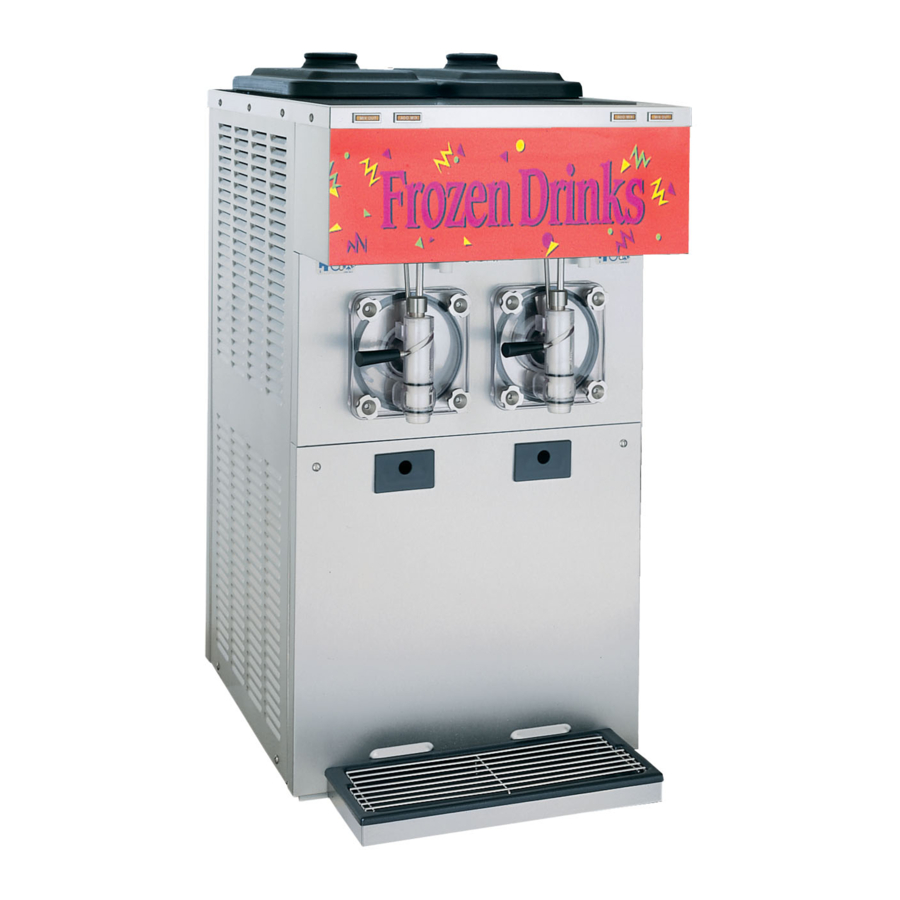
Frozen beverage unit with raised drip tray
Hide thumbs
Also See for 432:
- Operator's manual (42 pages) ,
- Operator's manual (38 pages) ,
- Original operating instructions (39 pages)

Subscribe to Our Youtube Channel
Related Manuals for Taylor 432


Summary of Contents for Taylor 432
- Page 1 OPERATOR’S MANUAL Model 432 Frozen Beverage Unit with Raised Drip Tray Original Operating Instructions May, 2008 (Original Publication) 066484-M (Updated 7/30/2020)
- Page 2 Note: Only instructions originating from the factory or its authorized translation representative(s) are considered to be the original set of instructions. © 2008 Taylor Company (Updated 7/30/2020) 066484-M Any unauthorized reproduction, disclosure, or distribution of copies by any person of any portion of this work may be...
-
Page 3: Table Of Contents
Model 432 Parts Identification ........ - Page 4 Section 7: Operator Checklist During Cleaning and Sanitizing......... . . 7-1 Troubleshooting Bacterial Count.
-
Page 5: Section 1: To The Installer
® of Taylor machines. personal injury. • Only Taylor service personnel should perform For Indoor Use Only: This machine is designed to installation, maintenance, and repairs on Taylor operate indoors, under normal ambient temperatures of machines. 70ºF to 75ºF (21ºC to 24ºC). The machine has •... -
Page 6: Air-Cooled Machines
• If the supply cord is damaged, it must be replaced by a Taylor service technician in order to avoid a hazard. WARNING! This machine must be properly • Secure the supply cord ground lead to the grounded. -
Page 7: Beater Rotation
For information regarding applicable local laws, CAUTION! This machine contains fluorinated please contact your local authorized Taylor distributor. greenhouse gases (F-Gas) to provide refrigeration using a hermetically sealed circuit or within foam insulation. - Page 8 TO THE INSTALLER Notes: To the Installer Model 432...
-
Page 9: Section 2: To The Operator
It should also be noted that Taylor does not warrant the refrigerant were installed in the machine, system refrigerant used in its equipment. For example, if the... - Page 10 TO THE OPERATOR Notes: To the Operator Model 432...
-
Page 11: Section 3: Safety
Safety Section 3 We at Taylor Company are concerned about the safety of the operator at all times when they are coming in contact with the machine and its parts. Taylor makes every effort WARNING! Avoid injury. to design and manufacture built-in safety features to •... - Page 12 DO NOT put objects or fingers in the door Failure to follow these instructions may result in spout. This may contaminate the product and electrocution. Contact your local authorized Taylor cause severe personal injury from blade distributor for service. contact.
- Page 13 Noise Level: Airborne noise emission does not exceed 78 dB(A) when measured at a distance of 39 in. (1.0 m) from the surface of the machine and at a height of 62 in. (1.6 m) from the floor. Safety Model 432...
- Page 14 SAFETY Notes: Safety Model 432...
-
Page 15: Section 4: Operator Parts Identification
Operator Parts Identification Section 4 Model 432 Figure 4-1 Operator Parts Identification Model 432... -
Page 16: Model 432 Parts Identification
OPERATOR PARTS IDENTIFICATION Model 432 Parts Identification Item Description Part No. Item Description Part No. Cover A.-Hopper X52452 Lens- Decorative Plate 052359 Panel-Rear 052363 Panel- Side- Left 066453 Panel-Side Right 066452 Tray- Drip 066420 Panel-Front Lower 066405 Tube- Feed W/DBL 3/8 Hole... -
Page 17: Beater Door Assembly
OPERATOR PARTS IDENTIFICATION Beater Door Assembly Figure 4-2 Operator Parts Identification Model 432... -
Page 18: Beater Door Assembly Parts Identification
Beater A. - 4 QT. 1 Pin X49490 Handle A.-Draw-Slush X47384 Blade- Scraper- Plastic 046237 Valve Draw - Slush 047734 Arm- Torque *432* SOFT 052450-SP Pin A.- Valve Handle X25929 Shaft - Beater 035418 O-Ring- 1”OD X.139W 032504 Seal - Drive Shaft... -
Page 19: Accessories
OPERATOR PARTS IDENTIFICATION Accessories Apply the appropriate Taylor approved food safe lubricant. Figure 4-3 Item Description Part No. Item Description Part No. Brush- Mix Pump Body- 3X7 023316 Kit A.- Tune Up X50413 Brush- Double Ended 013072 Blade- Scraper- Plastic 046237 Brush- Rear BRG 1”D X 2”... - Page 20 OPERATOR PARTS IDENTIFICATION Notes: Operator Parts Identification Model 432...
-
Page 21: Section 5: User Interface
= OFF re-established. Display Light Switch (Item 3) = WASH The display light switch is located under the control channel. The left position is OFF. The right position is ON and activates the display light. User Interface Model 432... -
Page 22: Indicator Light-Mix Out (Item 4)
Indicator Light—ADD MIX (Item 5) A MIX LEVEL indicating light is located on the front of the machine. When the light is flashing, the mix hopper has a low supply of product and should be refilled as soon as possible. User Interface Model 432... -
Page 23: Section 6: Operating Procedures
Operating Procedures Section 6 The Model 432 freezer is designed to produce shake or 11155 slush product at the desired thickness. This machine has two 4 qt. freezing cylinders. We begin our instructions at the point where we enter the store in the morning and find the parts disassembled and laid out to air dry from the previous night’s ... - Page 24 11354 beater pin. Apply the appropriate Taylor approved food safe lubricant. Figure 6-7 7. Insert the torque rotor end with the guide bearing into Figure 6-5 the pilot hole in the center of the driveshaft. The hole 5.
- Page 25 Replace any damaged parts. 9. Install the O-rings on the draw valve and lubricate. Apply the appropriate Taylor approved food safe lubricant. Figure 6-11 12. Insert the ice buster through the door spout and into the slot located just above the lower O-ring.
- Page 26 Install the four handscrews on the Apply the appropriate door and tighten them equally in a crisscross pattern. Taylor approved food safe lubricant. 101659 Figure 6-14 15. Screw the prime plug into position on the front of the door.
-
Page 27: Sanitizing
L] of Stera-Sheen®). Use warm water and follow the manufacturer’s specifications. 2. Pour the sanitizing solution into the hopper and allow it to flow into the freezing cylinder. Figure 6-20 20. Repeat step 1through step 19 for the other side of Operating Procedures Model 432... -
Page 28: Priming
This will force out any remaining sanitizing solution. When full strength mix is flowing from the door spout, move the draw handle to the left. Operating Procedures Model 432... -
Page 29: Closing Procedure
WASH position and move the draw handle to the right. When all the product stops flowing from the door spout, move the draw handle to Figure 6-28 the left and place the power switch in the OFF Operating Procedures Model 432... -
Page 30: Rinsing
4. Repeat step 1 through step 3 for the other side of the dilute according to label instructions. machine. Important! Follow the label directions. Too strong of a solution can cause parts damage, while too mild of a solution will not provide adequate cleaning. Make sure all Operating Procedures Model 432... - Page 31 Place all the cleaned parts on a clean, dry surface to air dry. 5. Return to the freezer with a small amount of cleaning solution. Brush-clean the rear shell bearing at the back of the freezing cylinder with the black bristle brush. Operating Procedures Model 432...
- Page 32 OPERATING PROCEDURES Notes: 6-10 Operating Procedures Model 432...
-
Page 33: Section 7: Operator Checklist
Do not prime the machine with rerun. When using rerun, skim off the foam and discard, then mix the rerun with fresh mix in a ratio of 50:50 during the day's operation. Operator Checklist Model 432... -
Page 34: Winter Storage
Disconnect the freezer from the main power source to prevent possible electrical damage. Your local Taylor distributor can perform this service for you. Wrap detachable parts of the freezer such as beater, blades, driveshaft, and freezer door, and place in a protected dry place. -
Page 35: Section 8: Troubleshooting Guide
Improper mixing of product. b. Carefully follow directions for mixing - - - product. c. The viscosity adjustment is set c. Adjust the viscosity control. incorrectly. d. The torque arm is not installed. d. Install the torque arm. Troubleshooting Guide Model 432... - Page 36 7. Excessive leakage into a. Improper or inadequate lubrication a. Use correct lubricant (Taylor Lube) rear drip pan. of driveshaft seal. and follow lubrication procedures. b. Bad or missing seal on driveshaft.
- Page 37 Maximum if necessary. Black Bristle Brush - Inspect and replace Maximum 1" x 2" x 14” if necessary. White Bristle Brush - Inspect and replace Maximum 1-1/2" x 2" x 3” if necessary. Parts Replacement Schedule Model 432...
- Page 38 PARTS REPLACEMENT SCHEDULE Notes: Parts Replacement Schedule Model 432...
- Page 39 LIMITED WARRANTY Taylor warrants the Product against failure due to defect in materials or workmanship under normal use and service as follows. All warranty periods begin on the date of original Product installation. If a part fails due to defect during the applicable warranty period, Taylor, through an authorized Taylor distributor or service agency, will provide a new or ...
- Page 40 LEGAL REMEDIES The owner must notify Taylor in writing, by certified or registered letter to the following address, of any defect or complaint with the Product, stating the defect or complaint and a specific request for repair, replacement, or other correction of the Product under warranty, mailed at least thirty (30) days before pursuing any legal rights or remedies.
- Page 41 Taylor warrants the Parts against failure due to defect in materials or workmanship under normal use and service as follows. All warranty periods begin on the date of original installation of the Part in the Taylor unit. If a Part fails due to defect during the applicable warranty period, Taylor, through an authorized Taylor distributor or service agency, will provide a new or remanufactured Part, at Taylor’s option, to replace the failed defective Part at no charge for the Part.
- Page 42 Taylor. 5. Replacement of wear items designated as Class “000” Parts in the Taylor Operator’s Manual, as well as any release sheets and clips for the Product’s upper platen assembly.
- Page 43 LEGAL REMEDIES The owner must notify Taylor in writing, by certified or registered letter to the following address, of any defect or complaint with the Part, stating the defect or complaint and a specific request for repair, replacement, or other correction of the Part under warranty, mailed at least thirty (30) days before pursuing any legal rights or remedies.
- Page 44 LIMITED WARRANTY ON PARTS Notes: 11-4 Limited Warranty on Parts Model 432...
Need help?
Do you have a question about the 432 and is the answer not in the manual?
Questions and answers