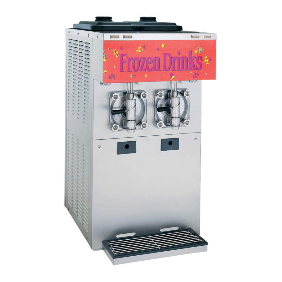
Taylor 432 Operator's Manual
Shake/slush freezer
Hide thumbs
Also See for 432:
- Operator's manual (38 pages) ,
- Operator's manual (44 pages) ,
- Original operating instructions (39 pages)

Subscribe to Our Youtube Channel
Related Manuals for Taylor 432


Summary of Contents for Taylor 432
- Page 1 OPERATOR’S MANUAL Model 432 Shake/Slush Freezer Original Operating Instructions 10/98 (Original Publication) 053081-M (Updated 6/28/2018)
- Page 2 Note: Only instructions originating from the factory or its authorized translation representative(s) are considered to be the original set of instructions. © 1998 Taylor Company (Updated 6/28/2018) 053081-M Any unauthorized reproduction, disclosure, or distribution of copies by any person of any portion of this work may be...
-
Page 3: Table Of Contents
Beater Rotation ....................1-3 Refrigerant ......................1-3 Section 2: To the Operator Section 3: Safety Section 4: Operator Parts Identification Model 432 ......................4-1 Beater Door Assembly ..................4-3 Accessories......................4-5 Section 5: User Interface Control Switch ....................5-1 Push-Button Switch.................... 5-1 Display Light Switch ................... - Page 4 Table of Contents Section 7: Operator’s Checklist During Cleaning and Sanitizing................7-1 Troubleshooting Bacterial Count................ 7-1 Regular Maintenance Checks ................7-1 Winter Storage ....................7-2 Section 8: Troubleshooting Guide Section 9: Parts Replacement Schedule Section 10: Limited Warranty on Equipment Section 11: Limited Warranty on Parts 053081-M...
-
Page 5: Section 1: To The Installer
Taylor machines. 104ºF (40ºC) at reduced capacities. • Only authorized Taylor service personnel should perform installation, maintenance, and repairs on Taylor machines. • Authorized service personnel should consult WARNING! This machine must NOT be OSHA Standard 29CFRI910.147 or the... -
Page 6: Air-Cooled Machines
If the supply cord is damaged, it must be replaced by an label on the machine. Check the data label(s) on the authorized Taylor service technician in order to avoid a freezer for branch circuit overcurrent protection or fuse, hazard. -
Page 7: Beater Rotation
It is recommended that beater rotation adjustment be regarding refrigerant recovery, recycling, and reclaiming performed by an authorized Taylor service technician. systems. For information regarding applicable local laws, please contact your local authorized Taylor distributor. - Page 8 TO THE INSTALLER Notes: Model 432 To the Installer...
-
Page 9: Section 2: To The Operator
If you require technical assistance, please contact your local authorized Taylor distributor. Note: Your Taylor warranty is valid only if the parts are authorized Taylor parts, purchased from the local authorized Taylor distributor, and only if all required service work is provided by an authorized Taylor service technician. - Page 10 Manual is subject to change without notice. known to any technician he employs. It should also be noted that Taylor does not warrant the refrigerant used in its equipment. For example, if the refrigerant is lost during the course of ordinary service to...
-
Page 11: Section 3: Safety
Safety Section 3 We at Taylor Company are concerned about the safety of • The main power supplies to the machine must the operator at all times when they are coming in contact be disconnected prior to performing installation, with the machine and its parts. Taylor makes every effort repairs, or maintenance. - Page 12 (1.6 m) from the floor. moving for any reason. Two or more persons are required to safely move this machine. Failure to comply may result in personal injury or damage to the machine. IMPORTANT! Access to the service area of Model 432 Safety...
-
Page 13: Section 4: Operator Parts Identification
Operator Parts Identification Section 4 Model 432 Figure 4-1 Operator Parts Identification Model 432... - Page 14 OPERATOR PARTS IDENTIFICATION Model 432 Parts Identification Item Description Part No. Item Description Part No. Cover A.- Hopper X52452 Pan- Drip 17-1/4" Long 027504 Panel- Rear 052363 Stud- Nose Cone 013496 Panel- Side Right- Open 052526 Panel A.- Upper Front...
-
Page 15: Beater Door Assembly
OPERATOR PARTS IDENTIFICATION Beater Door Assembly Figure 4-2 Operator Parts Identification Model 432... - Page 16 Valve Draw - Slush 047734 Shaft- Beater 035418 Pin A.- Valve Handle X25929 Seal- Drive Shaft 032560 O-Ring- 0.291" OD x 0.080" W 018550 O-ring 7/8" OD x 0.139" W 025307 Arm - Torque 052450 Torque Assembly X50382 Model 432 Operator Parts Identification...
-
Page 17: Accessories
Kit A. - Tune Up X39969 Brush - Draw Valve 1-1/2" x 3" 014753 Brush - Mix Pump Body- 3" x 7" 023316 Lubricant - Taylor 047518 Pail - 6 Qt. 023348 Sanitizer - Stera Sheen - Green 055492 Brush - Double Ended 013072 Panel A.- Air Guide... - Page 18 OPERATOR PARTS IDENTIFICATION Notes: Model 432 Operator Parts Identification...
-
Page 19: Section 5: User Interface
= WASH button Display Light Switch The display light switch is located under the control channel. The left position is OFF. The right position is ON, and activates the display light. User Interface Model 432... -
Page 20: Indicator Light-Mix Out
The ADD MIX indicating light is located on the front of the machine. When the ADD MIX indicating light is flashing, the mix hopper has a low supply of product and should be refilled as soon as possible. Model 432 User Interface... -
Page 21: Section 6: Operating Procedures
Operating Procedures Section 6 The Model 432 freezer is designed to produce shake or slush product at the desired thickness. This machine has a 4 qt. (3.8 L) freezing cylinder. We begin our instructions at the point where we enter the store in the morning and find the parts disassembled and laid out to air dry from the previous night’s brush... - Page 22 O-rings, and all sides of the door assembly, including the inside of the draw valve bore. Replace any damaged parts. Note: Steps 8 through 12 assemble the freezer door with the ice buster (doorspout clearing device). Model 432 Operating Procedures...
- Page 23 101612 Figure 6-9 10. Rotate the draw valve so the flats on the top of the draw valve are perpendicular to the door face. Figure 6-12 101650 Figure 6-10 Operating Procedures Model 432...
- Page 24 14. Install the door on the four studs on the front of the 101653 freezing cylinder. Install the four handscrews on the door, and tighten them equally in a crisscross manner. 101651 Figure 6-16 Figure 6-14 Model 432 Operating Procedures...
-
Page 25: Sanitizing
® ® Kay-5 or 2 gal. (7.6 L) of Stera-Sheen ). Use warm and place the control switch in the OFF position. water and follow the manufacturer’s specifications. Operating Procedures Model 432... -
Page 26: Priming
This will force out any remaining sanitizing solution. When full-strength mix is flowing from the door spout, move the draw handle to the left. Important! Failure to remove all sanitizing solution may result in damage to the freezing cylinder. Model 432 Operating Procedures... -
Page 27: Closing Procedure
OFF position. Place the sanitized lid on the rerun container and place it in the walk-in cooler. Operating Procedures Model 432... -
Page 28: Cleaning
7. Repeat steps 1 through 6 for the other side of the ® ® Kay-5 or Stera-Sheen ). Use warm water and machine. follow the manufacturer’s specifications. If another approved cleaner is used, dilute according to label instructions. Model 432 Operating Procedures... -
Page 29: Section 7: Operator's Checklist
Do not prime the machine with rerun. When using rerun, skim off the foam and discard, then mix the rerun with fresh mix in a ratio of 50/50 during the day's operation. Operator’s Checklist Model 432... -
Page 30: Winter Storage
Disconnect the freezer from the main power source to prevent possible electrical damage. Your local Taylor distributor can perform this service for you. Wrap detachable parts of the freezer such as beater, blades, drive shaft, and freezer door, and place in a protected dry place. -
Page 31: Section 8: Troubleshooting Guide
- - - product. c. The viscosity adjustment is set c. Adjust accordingly. page 5-2 incorrectly. d. Dirty condensers. d. Clean regularly. page 7-1 e. Incorrect beater rotation.(Rotation e. Contact service technician. page 1-3 must be clockwise.) Troubleshooting Guide Model 432... - Page 32 - - - bent/damaged. replace. 7. Excessive leakage into a. Improper or inadequate lubrication a. Use correct lubricant (Taylor Lube) page 6-1 rear drip pan. of drive shaft seal. and follow lubrication procedures. b. Bad or missing seal on drive shaft.
- Page 33 Black Bristle Brush - 1” x 2” Inspect and replace Maximum if necessary. Brush - 1-1/2” X 2” Inspect and replace Maximum if necessary. Brush - 3” x 7” Inspect and replace Maximum if necessary. Parts Replacement Schedule Model 432...
- Page 34 PARTS REPLACEMENT SCHEDULE Notes: Model 432 Parts Replacement Schedule...
-
Page 35: Section 10: Limited Warranty On Equipment
Taylor, through an authorized Taylor distributor or service agency, will provide a new or remanufactured part, at Taylor’s option, to replace the failed defective part at no charge for the part. Except as otherwise stated herein, these are Taylor’s exclusive obligations under this limited warranty for a Product failure. This limited warranty is subject to all provisions, conditions, limitations, and exclusions listed below and on the reverse (if any) of this document. - Page 36 7. Failure, damage, or repairs due to faulty installation, misapplication, abuse, no or improper servicing, unauthorized alteration or improper operation or use as indicated in the Taylor Operator’s Manual, including but not limited to the failure to use proper assembly and cleaning techniques, tools, or approved cleaning supplies.
- Page 37 LEGAL REMEDIES The owner must notify Taylor in writing, by certified or registered letter to the following address, of any defect or complaint with the Product, stating the defect or complaint and a specific request for repair, replacement, or other correction of the Product under warranty, mailed at least thirty (30) days before pursuing any legal rights or remedies.
- Page 38 LIMITED WARRANTY ON EQUIPMENT Notes: 10-4 Model 432 Limited Warranty on...
-
Page 39: Section 11: Limited Warranty On Parts
Taylor warrants the Parts against failure due to defect in materials or workmanship under normal use and service as follows. All warranty periods begin on the date of original installation of the Part in the Taylor unit. If a Part fails due to defect during the applicable warranty period, Taylor, through an authorized Taylor distributor or service agency, will provide a new or remanufactured Part, at Taylor’s option, to replace the failed defective Part at no charge for the Part. - Page 40 Taylor. 5. Replacement of wear items designated as Class “000” Parts in the Taylor Operator’s Manual, as well as any release sheets and clips for the Product’s upper platen assembly.
- Page 41 LEGAL REMEDIES The owner must notify Taylor in writing, by certified or registered letter to the following address, of any defect or complaint with the Part, stating the defect or complaint and a specific request for repair, replacement, or other correction of the Part under warranty, mailed at least thirty (30) days before pursuing any legal rights or remedies.
- Page 42 LIMITED WARRANTY ON PARTS Notes: 11-4 Model 432 Limited Warranty on Parts...
Need help?
Do you have a question about the 432 and is the answer not in the manual?
Questions and answers