Taylor 432 Operator's Manual
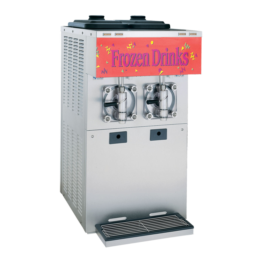
Frozen beverage unit with raised drip tray
Hide thumbs
Also See for 432:
- Operator's manual (42 pages) ,
- Operator's manual (44 pages) ,
- Original operating instructions (39 pages)

Related Manuals for Taylor 432


Summary of Contents for Taylor 432
- Page 1 OPERATOR'S MANUAL Model 432 Frozen Beverage Unit With Raised Drip Tray Original Operating Instructions 066484-M May, 2008 (Original Publication) (Updated 9/18/14)
- Page 2 Complete this page for quick reference when service is required: Taylor Distributor: Address: Phone: Fax: E-mail: Service: Parts: Date of Installation: Information found on the data label: Model Number: Serial Number: Electrical Specs: Voltage Cycle Phase Maximum Fuse Size: Minimum Wire Ampacity: E 2008 Carrier Commercial Refrigeration, Inc.
-
Page 3: Table Of Contents
....... Model 432 ............ - Page 4 Statutory Damages of up to $250,000 (17 USC 504) for infringement, and may result in further civil and criminal penalties. All rights reserved. Taylor Company a division of Carrier Commercial Refrigeration, Inc. 750 N. Blackhawk Blvd. Rockton, IL 61072 Model 432 Table of Contents...
-
Page 5: To The Installer
NEVER use service of Taylor® equipment. a water jet or hose to rinse or clean the unit. Failure Only authorized Taylor service personnel to follow this instruction may result in electrocution. should perform installation, maintenance, and repairs on Taylor equipment. -
Page 6: Electrical Connections
If the supply cord is damaged, it must be specifications. Refer to the wiring diagram provided replaced by an authorized Taylor service inside of the electrical box, for proper power technician in order to avoid a hazard. -
Page 7: Refrigerant
R404A. This refrigerant is generally considered non-toxic and non-flammable, with an Ozone Depleting Potential (ODP) of zero (0). Taylor reminds technicians to be aware of and in compliance with local government laws However, any gas under pressure is potentially regarding refrigerant recovery, recycling, and hazardous and must be handled with caution. -
Page 8: To The Operator
The unauthorized use of alternate refrigerants will void your Taylor compressor warranty. It is the Note: Your Taylor warranty is valid only if the parts unit owner's responsibility to make this fact known to are authorized Taylor parts, purchased from the any technician he employs. -
Page 9: Safety
We, at Taylor Company, are concerned about the safety of the operator at all times when they are coming in contact with the unit and its parts. Taylor makes every effort to design and manufacture All repairs should be performed by an built-in safety features to protect both operators and authorized Taylor service technician. - Page 10 78 dB(A) when measured at a distance of safely move this unit. Failure to comply may result in 1.0 meter from the surface of the machine and at a personal injury or damage to the unit. height of 1.6 meters from the floor. Safety Model 432...
- Page 11 Notes: Model 432 Safety...
-
Page 12: Operator Parts Identification
Section 4 Operator Parts Identification Model 432 Figure 1 110309 Operator Parts Identification Model 432... - Page 13 Part No. Cover A.- Hopper Bulb- Light- Fluorescent X52452 045445 U- Shape Panel- Rear 052363 Bracket- Light 052243 Panel- Side- Right 432 Collar 066452 Lens- Decorative Plate 052359 Panel- Front- Lower 066405 Panel- Side- Left 066453 Gasket- Base Pan 052377...
-
Page 14: Beater Door Assembly
Beater Door Assembly Figure 2 110309 Operator Parts Identification Model 432... - Page 15 Nut- Stud 043666 Torque Assembly X66393 Clip- Scraper Blade 046238 Bearing- Guide 014496 Plug- Prime 050405 Gasket- Door 5.109” ID x 5.630 014030 O- Ring .563 OD x .070 W 043758 Bearing- Front 013116 110309 Model 432 Operator Parts Identification...
-
Page 16: Accessories
X39969- SP1 Kit A.-Tune Up *Slush* *Note: A sample container of sanitizer is sent with the unit. For reorders, order Stera Sheen part no. 055492 (100 packs) or Kay-5 part no. 041082 (125 packs). 140718 Operator Parts Identification Model 432... -
Page 17: Important: To The Operator
Note: If the freezer is unplugged from the wall = The “OFF” button. receptacle, it will be necessary to press the push-button switch for the freezer to operate once = The “WASH” button. power is re-established. Model 432 Important: To the Operator... -
Page 18: Display Light Switch (Item 3)
After making mix out indicator lights illuminates. Refrigeration will an adjustment, allow the refrigeration system to restart 30 seconds after the mix supply is cycle 2 or 3 times to accurately evaluate the replenished. viscosity. Important: To the Operator Model 432... -
Page 19: Operating Procedures
Section 6 Operating Procedures The Model 432 freezer is designed to produce shake Note: To ensure that the mix does not leak out of or slush product at the desired thickness. This unit the back of the freezing cylinder, the middle section has two 4 quart freezing cylinders. - Page 20 Slide the beater the remainder of the way into the 12 o'clock position. freezing cylinder and over the end of the drive shaft. The beater assembly should not protrude beyond the front of the freezing cylinder. Figure 8 Figure 10 Operating Procedures Model 432...
- Page 21 Insert the ice buster through the door spout and into Insert the draw valve into the door, leaving the slot located just above the lower o-ring. approximately half of the valve sticking out the top of the door. Figure 12 Figure 14 Model 432 Operating Procedures...
- Page 22 Figure 16 Step 13 Install the door on the four studs on the front of the freezing cylinder. Install the four handscrews on the door and tighten them equally in a criss-cross manner. Figure 19 080730 Operating Procedures Model 432...
-
Page 23: Sanitizing
Figure 23 Step 3 While the solution is flowing into the freezing cylinder, brush clean the mix hopper, air/mix feed Figure 21 tube and mix inlet hole. Model 432 Operating Procedures... -
Page 24: Priming
Step 2 When the mix has stopped bubbling down into the freezing cylinder, install the air/mix feed tube in the mix inlet hole with the hole side down. Figure 25 Figure 27 Operating Procedures Model 432... -
Page 25: Closing Procedure
Figure 29 in one of the hoppers. Repeat these steps for the other side of the unit. ALWAYS FOLLOW LOCAL HEALTH CODES. Note: An air/mix feed tube should only be installed in one of the hoppers. 140718 Model 432 Operating Procedures... -
Page 26: Rinsing
Note: If the drip pans are filled with an excessive cylinder, brush-clean the mix hopper and mix inlet amount of mix, it is an indication the drive shaft hole. seals should be replaced or properly lubricated. Operating Procedures Model 432... -
Page 27: Brush Cleaning
Wipe clean all exterior surfaces of the freezer. groove. With the other hand, push the top of the o-ring forward until it rolls out of the groove and can be removed easily. Repeat these steps for the other side of the unit. Model 432 Operating Procedures... -
Page 28: Important: Operator Checklist
Note: For machines equipped with an air NOT prime the machine with rerun. When filter, it will be necessary to vacuum the filters using rerun, skim off the foam and discard, on a monthly schedule. Important: Operator Checklist Model 432... -
Page 29: Winter Storage
Disconnect the freezer from the main power source which attract mice and other vermin. to prevent possible electrical damage. Your local Taylor Distributor can perform this service for you. Model 432 Important: Operator Checklist... -
Page 30: Troubleshooting Guide
3. No compressor operation a. Beater motor is out on a. Place control switch in “OFF” position. Press the in the “AUTO” mode. overload. push-button switch. Return control switch to “AUTO”. b. Condenser dirty A/C. b. Clean condenser monthly. Troubleshooting Guide Model 432... - Page 31 Replace or install front bearing. missing. 7. Excessive leakage into a. Improper or inadequate a. Use correct lubricant (Taylor Lube) and follow rear drip pan. lubrication of drive shaft lubrication procedures. seal. b. Bad or missing seal on b. Replace seal every 3 months.
-
Page 32: Parts Replacement Schedule
Inspect & Replace Maximum if Necessary Black Bristle Brush - 1" x 2" x 14” Inspect & Replace Maximum if Necessary White Bristle Brush - 1-1/2" x 2" x 3” Inspect & Replace Maximum if Necessary Parts Replacement Schedule Model 432... -
Page 33: Limited Warranty On Equipment
Taylor, through an authorized Taylor distributor or service agency, will provide a new or re-manufactured part, at Taylor’s option, to replace the failed defective part at no charge for the part. Except as otherwise stated herein, these are Taylor’s exclusive obligations under this limited warranty for a Product failure. - Page 34 LEGAL REMEDIES The owner must notify Taylor in writing, by certified or registered letter to the following address, of any defect or complaint with the Product, stating the defect or complaint and a specific request for repair, replacement, or other correction of the Product under warranty, mailed at least thirty (30) days before pursuing any legal rights or remedies.
-
Page 35: Limited Warranty On Parts
Taylor warrants the Parts against failure due to defect in materials or workmanship under normal use and service as follows. All warranty periods begin on the date of original installation of the Part in the Taylor unit. If a Part fails due to defect during the applicable warranty period, Taylor, through an authorized Taylor distributor or service agency, will provide a new or re-manufactured Part, at Taylor’s option, to replace the failed defective Part at no... - Page 36 Parts or the units in which they are installed repaired or altered in any way so as, in the judgment of Taylor, to adversely affect performance, or normal wear or deterioration.
-
Page 37: Taylor Company
LEGAL REMEDIES The owner must notify Taylor in writing, by certified or registered letter to the following address, of any defect or complaint with the Part, stating the defect or complaint and a specific request for repair, replacement, or other correction of the Part under warranty, mailed at least thirty (30) days before pursuing any legal rights or remedies. - Page 38 BLACK WHITE/BLACK STRIPE LEFT LEFT PUSHBUTTON POWER SWITCH SWITCH BLK/WHT AUTO CORCOM FILTER WASH COMPRESSOR LEFT BEATER HIGH PRESSURE OVERLOAD AUTO SWITCH RELAY WASH ORANGE RED/WHT AUTO LEFT BEATER RELAY COIL WASH LEFT COMPRESSOR RELAY COIL BLK/WHT YELLOW LEFT SET SWITCH PCB A.
Need help?
Do you have a question about the 432 and is the answer not in the manual?
Questions and answers