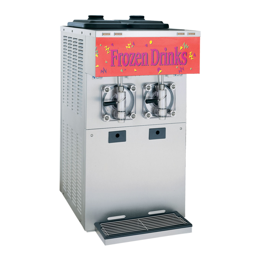
Taylor 432 Original Operating Instructions
Tim hortons slush freezer
Hide thumbs
Also See for 432:
- Operator's manual (42 pages) ,
- Operator's manual (38 pages) ,
- Operator's manual (44 pages)

Related Manuals for Taylor 432


Summary of Contents for Taylor 432
- Page 1 OPERATOR'S MANUAL Model 432 Tim Hortons Slush Freezer Original Operating Instructions 068462-M 10/8/10 (Original Publication) Updated 1/23/15...
- Page 2 Complete this page for quick reference when service is required: Taylor Distributor: Address: Phone: Fax: E-mail: Service: Parts: Date of Installation: Information found on the data label: Model Number: Serial Number: Electrical Specs: Voltage Cycle Phase Maximum Fuse Size: Minimum Wire Ampacity: 2010 Carrier Commercial Refrigeration, Inc.
-
Page 3: Table Of Contents
............. . Model 432 Tim Hortons... - Page 4 Statutory Damages of up to $250,000 (17 USC 504) for infringement, and may result in further civil and criminal penalties. All rights reserved. Taylor Company a division of Carrier Commercial Refrigeration, Inc. 750 N. Blackhawk Blvd. Rockton, IL 61072 Table of Contents Model 432 Tim Hortons...
-
Page 5: To The Installer
Failure to follow this instruction may result in Uncrate the unit and inspect it for damage. Report personal injury or death from electrical shock or any damage to your Taylor Distributor. hazardous moving parts as well as poor performance or damage to the equipment. -
Page 6: Air Cooled Units
Please contact your local authorities. If the supply cord is damaged, it must be replaced by an authorized Taylor service Each unit requires one power supply for each data technician in order to avoid a hazard. -
Page 7: Refrigerant
Refrigerant In consideration of our environment, Taylor Taylor reminds technicians to be cautious of uses only earth friendly HFC refrigerants. The HFC government laws regarding refrigerant recovery, refrigerant used in this unit is R404A. This recycling, and reclaiming systems. If you have any... -
Page 8: To The Operator
The unauthorized use of alternate refrigerants will void your Taylor compressor warranty. It is the Note: Your Taylor warranty is valid only if the parts unit owner's responsibility to make this fact known to are authorized Taylor parts, purchased from the any technician he employs. -
Page 9: Safety
We, at Taylor Company, are concerned about the safety of the operator when he or she comes in contact with the freezer and its parts. Taylor has gone to extreme efforts to design and manufacture DO NOT operate the freezer unless it is built-in safety features to protect both you and the properly grounded. - Page 10 Failure to comply may result in 1.0 meter from the surface of the machine and at a personal injury or damage to the unit. height of 1.6 meters from the floor. 131009 Safety Model 432 Tim Hortons...
- Page 11 Notes Model 432 Tim Hortons Safety...
-
Page 12: Operator Parts Identification
Section 4 Operator Parts Identification 432 Exploded View Figure 1 150123 Operator Parts Identification Model 432 Tim Hortons... - Page 13 432 Exploded View Parts Identification ITEM DESCRIPTION PART NO. ITEM DESCRIPTION PART NO. COVER A.-HOPPER X52452 SHELF-DRIP TRAY 068600 PANEL-SIDE-LEFT *432* 66396 COLLAR-HOLDING .730DX.072 46551 PANEL-REAR *432* 52363 SCREW-10-32X3/4 SLTD OVAL 001086 SCREW-10-32X1/2 SLTD TRUSS 37734 TRAY-DRIP *432* HORTON 68581 PANEL A.-DUCT RT...
-
Page 14: Beater Door Assembly
Beater Door Assembly Figure 2 150123 Operator Parts Identification Model 432 Tim Hortons... - Page 15 O-RING - 1" OD X .139 W 032504 BEATER A. - 4 QT. 1 PIN X49490 VALVE DRAW - SLUSH 047734 SHAFT - BEATER 035418 PIN A.-VALVE HANDLE X25929 SEAL - DRIVE SHAFT 032560 141219 Model 432 Tim Hortons Operator Parts Identification...
-
Page 16: Accessories
PART NO. KIT A.-TUNE UP X50413A BRUSH-REAR BEARING 013071 1 X 2 X 14 BRUSH-MIX HOPPER 3 X 7 023316 BRUSH-DRAW VALVE 014753 PAIL-10 QT. 013163 1-1/2 X 3 BRUSH-DOUBLE ENDED 013072 141219 Operator Parts Identification Model 432 Tim Hortons... -
Page 17: Important: To The Operator
= OFF (SWITCH-TOGGLE-SPST 3/4 HP 250V) SPINNER INDICATOR LIGHT = WASH (LIGHT-GREEN-RECT 125V SPINNER) ADD MIX INDICATOR LIGHT (LIGHT-AMBER-RECT-12VDC ADD MIX) MIX OUT INDICATOR LIGHT (LIGHT-AMBER-RECT-12VDC MIX OUT) VISCOSITY ADJUSTMENT (BUSHING A.-TORQUE) Model 432 Tim Hortons Important: To the Operator... -
Page 18: Power Switch
The left position is “OFF”. The right position cycle 2 or 3 times to accurately evaluate the is “ON” and activates the display light. viscosity. Important: To the Operator Model 432 Tim Hortons... -
Page 19: Operating Procedures
Section 6 Operating Procedures The Model 432 freezer is designed to produce slush product at the desired thickness. This unit has a four quart freezing cylinder. We begin our instructions at the point where we enter the store in the morning and find the parts disassembled and laid out to air dry from the previous night's brush cleaning. - Page 20 Be sure the holes in the blade are groove on the long end of the torque rotor and securely positioned over the beater pin. lubricate the o-ring. Do not lubricate the guide bearing. Figure 8 Figure 10 131009 Operating Procedures Model 432 Tim Hortons...
- Page 21 (door spout clearing device). To assemble the door draw valve are perpendicular to the door face. with the ice buster, install the o-rings on the draw valve and lubricate. Figure 12 Figure 14 141219 Model 432 Tim Hortons Operating Procedures...
- Page 22 This will lock door. the ice buster in place. Install the draw handle pin and close the draw valve by moving the handle to the left. Figure 16 Figure 18 150123 Operating Procedures Model 432 Tim Hortons...
- Page 23 Note: Be sure to lift the draw lever when placing the door into position. Failure to do so may cause a failure to the related components. Figure 22 Repeat these steps for the other side of the unit. Figure 20 150123 Model 432 Tim Hortons Operating Procedures...
-
Page 24: Sanitizing
Step 3 Figure 26 While the solution is flowing into the freezing cylinder, brush clean the mix hopper and the mix inlet hole. Repeat these steps for the other side of the unit. 141219 Operating Procedures Model 432 Tim Hortons... -
Page 25: Priming
To disassemble this unit, the following items will be needed: Two cleaning pails Necessary brushes (provided with freezer) Figure 27 Cleaner Note: To identify the viscosity adjustment screw, see illustration on page 13. Single service towels 140717 Model 432 Tim Hortons Operating Procedures... -
Page 26: Draining Product From The Freezing Cylinder
Repeat this procedure until the rinse water being drawn from the freezing cylinder is clear. Repeat these steps for the other side of the unit. Repeat these steps for the other side of the unit. 140717 Operating Procedures Model 432 Tim Hortons... -
Page 27: Cleaning
“OFF” Step 3 position. Remove the front drip tray and the splash shield. Repeat these steps for the other side of the unit. Take them to the sink for cleaning. Model 432 Tim Hortons Operating Procedures... - Page 28 With the other hand, push the top of the o-ring forward until it rolls out of the groove and can be removed easily. Repeat these steps for the other side of the unit. Operating Procedures Model 432 Tim Hortons...
-
Page 29: Brush Cleaning
Note: For machines equipped with an air with rerun. When using rerun, skim off the filter, it will be necessary to clean the filters on foam and discard; then mix the rerun with a monthly schedule. Model 432 Tim Hortons Important: Operator Checklist... -
Page 30: Winter Storage
Disconnect the freezer from the main power source which attract mice and other vermin. to prevent possible electrical damage. Your local Taylor Distributor can perform this service for you. Important: Operator Checklist Model 432 Tim Hortons... -
Page 31: Troubleshooting Guide
Beater motor is out on a. Place control switch in “OFF” position. Press the in the “AUTO” mode. overload. reset button. Return control switch to “AUTO”. b. Condenser is dirty b. Clean condenser monthly. (air-cooled units). Model 432 Tim Hortons Troubleshooting Guide... - Page 32 Do not lubricate the square end. Contact an shaft. of drive shaft. authorized service technician. b. Rounded corners of drive b. Contact an authorized - - - service technician. shaft, drive coupling, or both. Troubleshooting Guide Model 432 Tim Hortons...
-
Page 33: Parts Replacement Schedule
Necessary Brush-Double Ended Inspect & Maximum Replace if Necessary Brush-Rear Bearing Inspect & Maximum Replace if 1 x 2 x 14 Necessary Brush-Draw Valve Inspect & Maximum Replace if 1-1/2 x 3 Necessary Model 432 Tim Hortons Parts Replacement Schedule... -
Page 34: Limited Warranty On Equipment
Taylor, through an authorized Taylor distributor or service agency, will provide a new or re-manufactured part, at Taylor’s option, to replace the failed defective part at no charge for the part. Except as otherwise stated herein, these are Taylor’s exclusive obligations under this limited warranty for a Product failure. - Page 35 LEGAL REMEDIES The owner must notify Taylor in writing, by certified or registered letter to the following address, of any defect or complaint with the Product, stating the defect or complaint and a specific request for repair, replacement, or other correction of the Product under warranty, mailed at least thirty (30) days before pursuing any legal rights or remedies.
-
Page 36: Limited Warranty On Parts
Taylor warrants the Parts against failure due to defect in materials or workmanship under normal use and service as follows. All warranty periods begin on the date of original installation of the Part in the Taylor unit. If a Part fails due to defect during the applicable warranty period, Taylor, through an authorized Taylor distributor or service agency, will provide a new or re-manufactured Part, at Taylor’s option, to replace the failed defective Part at no... - Page 37 Parts or the units in which they are installed repaired or altered in any way so as, in the judgment of Taylor, to adversely affect performance, or normal wear or deterioration.
-
Page 38: Taylor Company
LEGAL REMEDIES The owner must notify Taylor in writing, by certified or registered letter to the following address, of any defect or complaint with the Part, stating the defect or complaint and a specific request for repair, replacement, or other correction of the Part under warranty, mailed at least thirty (30) days before pursuing any legal rights or remedies. - Page 39 WHT/BLU BLU/WHT GRA/BLK RIGHT BEATER RELAY RIGHT BEATER MOTOR FIG.1 ORN/WHT RIGHT SUCTION SOLENOID RIGHT COMPRESSOR RELAY RIGHT LIQUID SOLENOID COMP CONTACTOR FIG.2 CONTACTOR BLK/WHT LIGHT SWITCH Taylor Company LIGHTING OPTIONAL Model 432 052145-27h 05/14 2014 Carrier Commercial Refrigeration, Inc.
Need help?
Do you have a question about the 432 and is the answer not in the manual?
Questions and answers