Sign In
Upload
Download
Table of Contents
Contents
Add to my manuals
Delete from my manuals
Share
URL of this page:
HTML Link:
Bookmark this page
Add
Manual will be automatically added to "My Manuals"
Print this page
×
Bookmark added
×
Added to my manuals
Manuals
Brands
Veeder-Root Manuals
Music Mixer
TLS-3 Series
Site prep and installation manual
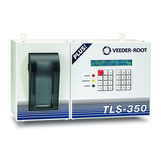
Veeder-Root TLS-3 Series Site Prep And Installation Manual
Hide thumbs
Also See for TLS-3 Series
:
Troubleshooting manual
(160 pages)
,
Quick help
(41 pages)
,
Installation manual
(22 pages)
1
2
Table Of Contents
3
4
5
6
7
8
9
10
11
12
13
14
15
16
17
18
19
20
21
22
23
24
25
26
27
28
29
30
31
32
33
34
35
36
37
38
39
40
41
42
43
44
45
46
47
48
49
50
51
52
53
54
55
56
57
58
59
60
61
62
63
64
65
66
67
68
69
70
71
72
73
74
75
76
77
78
79
80
81
82
83
84
85
86
87
88
89
90
91
page
of
91
Go
/
91
Contents
Table of Contents
Bookmarks
Table of Contents
Table of Contents
Introduction
Fixed-Feature Consoles
Modular Consoles
Contractor Certification Requirements
Related Documents
Documents Required to Install Equipment
Safety Precautions
National Electrical Code Compliance
Probe- and Sensor-To-Console Wiring
Power Wiring
Sensor and Probe Junction Boxes
Permissible Console Input/Output Connections
TLS-300/Proplus/Emc Basic Consoles
Figure 1. Permissible Inputs/Outputs by Area - TLS-300/Proplus/Emc Basic Console
TLS-350/Promax/Emc Consoles
Figure 2. TLS-350 Series/Promax/Emc Consoles - Plug-In Module Compartments
Planning Probe and Sensor Installations
Figure 3. TLS-300/Proplus/Emc Basic Typical Site/Forecourt Layout
Figure 4. TLS-350/Promax/Emc Typical Site/Forecourt Layout
Console Installation
Locating the Console
Mounting the Console
Figure 5. TLS-300/Proplus/Emc Basic Console Dimensions and Designated Conduit Knockouts
Figure 6. TLS-350/Promax/Emc Console Dimensions and Designated Conduit Knockouts
Wiring the Console
Figure 7. Wiring AC Power to the TLS-300/Proplus/Emc Basic Console
Checking the Ground Connection
Figure 8. Wiring AC Power to the TLS-350/Promax/Emc Console
Wiring Conduit Safety Issues
Determining Mag Probe Riser Size
Probe Riser Pipe Installation
Determining Mag Probe Length
Determining Mag Probe Length for Installation in a Vapor Extractor Riser
Figure 9. Determining the Minimum Mag Probe Length
Determining Mag Probe Length for Media-Isolated Installations
Figure 10. Determining Mag Probe Length for Installation in a Vapor Extractor Riser
Figure 11. Calculating the Correct Mag Probe Length for Media-Isolated Installation
Special Mag Probe Installation Kits
AST Installation Kit
Figure 12. Mag Probe AST Installation Kit
Vapor Extraction Riser Kit W/ Coupling Adaptor
Figure 13. Mag Probe Vapor Extractor W/Coupling Adaptor Installation Kit
Vapor Extraction Riser Kit W/O Coupling Adaptor
Figure 14. Mag Probe Vapor Extractor W/O Coupling Adaptor Installation Kit
Chem-ISO Kit
Figure 15. Mag Plus Probe Chem-ISO Kit
LPG-ISO Kit
Figure 16. Mag Plus Probe LPG-ISO Kit
Riser Cap Kit for Mag Probe Installations
Cap and Cord Grip Kit
Metal Cap and Ring Kit
Figure 17. Cap and Cord Grip Kit
Figure 18. Metal Cap and Ring Kit
Figure 19. Modifying an Existing Metal Riser Cap
Mag Probe Installation
UST/AST Tank - Dedicated Riser
UST Riser Cap Attachment
Figure 20. UST Probe Installation - Dedicated Riser
Figure 21. AST Probe Installation - Dedicated Riser
Figure 22. Installing a Riser Adaptor Beneath the Metal Cap and Adapter Ring
AST Riser Cap Attachment
UST Installation - Vapor Extractor Riser W/ Coupling Adaptor
Figure 23. Vapor Extractor Cabling Entry
UST Installation - Vapor Extractor Riser W/O Coupling Adaptor
Figure 24. Mag Probe Vapor Extractor Riser Installation - W/ Coupling Adaptor
Installing a Chem-ISO Mag Probe
Before You Begin
Figure 25. Mag Probe Vapor Extractor Riser Installation - W/O Coupling Adaptor
Attaching the Float to the Tube
Installing the Stainless Steel Tube into the Tank
Sealing the Stainless Steel Tube in the Tank Opening
Installing the Probe in the Stainless Steel Tube
Figure 26. Media Isolated Mag Plus Probe Installation Example
Entering Custom Float Size (In-Tank Setup - Ver. 22 or Later)
Installing a LPG-ISO Mag Probe
Before You Begin
Figure 27. Rain Shield Installed Position
Attaching the Float to the Tube
Installing the Stainless Steel Tube into the Tank
Sealing the Stainless Steel Tube in the Tank Opening
Installing the Probe in the Stainless Steel Tube
Entering Custom Float Size (In-Tank Setup - Ver. 22 or Later)
Figure 28. Media Isolated Mag Plus Probe Installation Example
Figure 29. Rain Shield Installed Position
Sensor Installation
Sensor Installation Diagrams
Figure 30. Example Interstitial Sensor Installation - Fiberglass UST
Figure 31. Example Interstitial Position Sensitive Sensor Installation - Steel UST
Figure 32. Example Interstitial Microsensor Installation - Steel UST
Figure 33. Example Microsensor Installation in Riser Containment - Steel UST
Figure 34. Example Hydrostatic Reservoir Single Float Sensor Installation
Figure 35. Example Hydrostatic Reservoir Dual Float Sensor Installation
Figure 36. Example Ground Temperature Thermistor Installation
Probe and Sensor Conduit Installation
Wiring Run Methods
Buried Rigid Conduit
Direct Burial Cable
Probe and Sensor Field Wiring
Sealing Field Connections
Wiring Run through Rigid Conduit
Direct Burial Cable
Connecting Probe/Sensor Wiring to Consoles
TLS-300/Proplus/Emc Basic Consoles
Probe and Sensor Wiring Precautions
Circuit Directory
Connecting Probes and Sensors to the Console
Connecting Devices to Power Area I/O Terminals
TLS-350/Promax/Emc Consoles
Module/Connector Positions and Labeling
Circuit Directory
Probe/Thermistor Interface Module - I.S. Bay
Probe/3 Sensor Interface Module - I.S. Bay
Interstitial Sensor Interface Module - I.S. Bay
Type B Interface Module - I.S. Bay
Type a Interface Module - I.S. Bay
Groundwater Sensor Interface Module - I.S. Bay
Vapor Sensor Interface Module - I.S. Bay
Smart Sensor Interface Module - I.S. Bay
Wiring Additional IS Bay Modules
4-Relay Output Module - Power Bay
I/O Combination Module - Power Bay
Pump Relay Monitor Module - Power Bay
Pump Sense Module - Power Bay
Wiring Additional Power Bay Modules
Connecting Serial Comm Modules
Serial Comm Modules
Miscellaneous Modules
Dispenser Interface Modules (Dims) - Consoles W/Bir Only
Before Applying Power to the Console
Appendix A: Wiring Record
Wiring Record
Module Position
Module Type
Probe/Sensor Identification
Terminal Identification
Color Code or Marking
Appendix B: Universal Sensor Mounting Kit
Introduction
Product Description
Kit Contents
Mounting Sensors
Advertisement
Quick Links
1
Table of Contents
2
Modular Consoles
3
Fixed-Feature Consoles
4
Probe- and Sensor-To-Console Wiring
Download this manual
Manual No: 576013-879
●
Revision: W
Veeder-Root TLS-3XX Consoles
Gilbarco EMC Series Consoles
ProPlus/ProMax Series Consoles
Site Prep and Installation Manual
Table of
Contents
Previous
Page
Next
Page
1
2
3
4
5
Advertisement
Table of Contents
Need help?
Do you have a question about the TLS-3 Series and is the answer not in the manual?
Ask a question
Questions and answers
Related Manuals for Veeder-Root TLS-3 Series
Music Mixer Veeder-Root TLS-350 System Setup Manual
(227 pages)
Industrial Equipment Veeder-Root TLS-3 Series Troubleshooting Manual
Consoles (160 pages)
Music Mixer Veeder-Root TLS-3 Series Quick Help
(41 pages)
Security Sensors Veeder-Root TLS-3 Series Installation Manual
Vapor pressure sensor (22 pages)
Measuring Instruments Veeder-Root TLS-3 Series Installation Manual
Isd balance vapor flow meter (16 pages)
Music Mixer Veeder-Root TLS-3 Series Quick Start Manual
Display replacement guide (9 pages)
Security System Veeder-Root TLS-3 Series Troubleshooting Manual
Warnings & alarms (9 pages)
Measuring Instruments Veeder-Root TLS-350 Troubleshooting Manual
(56 pages)
Accessories Veeder-Root TLS-350 Installation Manual
Vacuum sensors (45 pages)
Control Systems Veeder-Root TLS-300 Operator's Quick Manual
(36 pages)
Accessories Veeder-Root TLS-350 Installation Manual
Vacuum sensors (34 pages)
Control Unit Veeder-Root TLS-350 Installation Manual
Tcp/ip interface module (29 pages)
Music Mixer Veeder-Root TLS-350l Upgrade Instructions
(14 pages)
Control Unit Veeder-Root TLS-350 Series Installation Manual
Sensor interface modules (14 pages)
Power distribution unit Veeder-Root TLS-450/8600 Installation Manual
(10 pages)
Veeder-Root TLS-350, TLS-450PLUS Manual
(article)
This manual is also suitable for:
Tls-300 series
Tls-350 series
Gilbarco emc series
Gilbarco emc basic series
Proplus series
Promax series
Table of Contents
Print
Rename the bookmark
Delete bookmark?
Delete from my manuals?
Login
Sign In
OR
Sign in with Facebook
Sign in with Google
Upload manual
Upload from disk
Upload from URL
Need help?
Do you have a question about the TLS-3 Series and is the answer not in the manual?
Questions and answers