Veeder-Root TLS-3 Series Quick Help
Hide thumbs
Also See for TLS-3 Series:
- Troubleshooting manual (160 pages) ,
- Site prep and installation manual (91 pages) ,
- Installation manual (22 pages)
Table of Contents
Advertisement
Quick Links
Advertisement
Table of Contents

Related Manuals for Veeder-Root TLS-3 Series


Summary of Contents for Veeder-Root TLS-3 Series
- Page 1 ● Manual No: 576013-939 Rev.: F Operator's Quick Help TLS-3XX Series Consoles...
- Page 2 Notice Veeder-Root makes no warranty of any kind with regard to Veeder-Root reserves the right to change system options or this publication, including, but not limited to, the implied features, or the information contained in this publication. warranties of merchantability and fitness for a particular purpose.
-
Page 3: Table Of Contents
Table of Contents Page iii Console Operating Features ........1 Dual-Float Discriminating Sensor Alarms ....19 Key Functions ............2 Groundwater Sensor Alarms ........20 Automatic Reports ............ 3 Liquid Sensor Alarms ..........21 Automatic International-Only Reports ....... 4 Mag Sump Sensor Alarms ......... 22 Business Inventory Reconciliation (BIR Option) .. -
Page 4: Console Operating Features
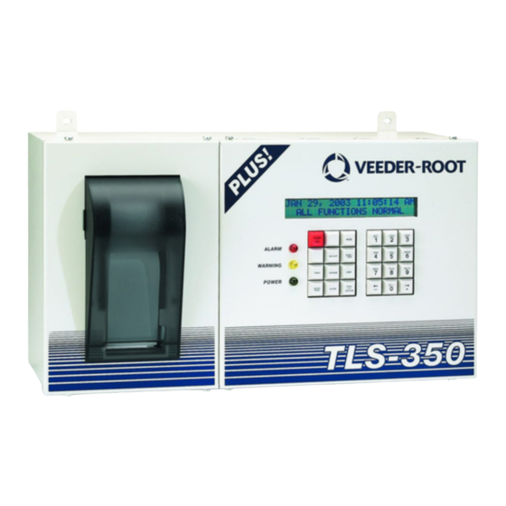
Console Operating Features Page 1 Display (showing operating mode - no alarms) MMM DD, YYYY HH:MM XM ALL FUNCTIONS NORMAL Alarm Light - Red ALARM MODE TEST Warning Light - Yellow FUNCT- BACKUP TION PRINT CHANGE STEP Power Light - Green PAPER TANK ENTER... -
Page 5: Key Functions
Key Functions Page 2 Press to silence the alarm. This will not Press to generate the various The period (.) is on key "1". The decimal point (•) is reset the display or disable any alarm reports. on the Right Arrow key (è). ALARM PRINT TEST... -
Page 6: Automatic Reports
Automatic Reports Page 3 ADJUSTED DELIVERY REPORT (BIR Option) INVENTORY INCREASE REPORT This report is generated after each deliv- T1: REGULAR UNLEAD During the delivery the TLS-350R is T1: PRODUCT 1 ery. It shows the volume of the tank con- INVENTORY INCREASE continuously monitoring any sales from ADJUSTED DELIVERY REPORT... -
Page 7: Automatic International-Only Reports
Automatic International-Only Reports Page 4 HOURLY RECONCILIATION MONITORING (optional, if enabled in setup) The TLS-350R continuously monitors the differ- Two Reconciliation Thresholds are set. An average difference DD-MM-YY ence between the volume of fuel dispensed greater than the lower threshold will cause a Reconciliation through the pumps and the volume of fuel drawn Warning. -
Page 8: Business Inventory Reconciliation (Bir Option)
Business Inventory Reconciliation (BIR Option) Page 5 The TLS-350R, in addition to accurately measuring the con- TO PRINT A RECONCILIATION REPORT tents of each tank, also monitors the amount of fuel dis- Press Mode until the display reads: pensed at the pumps. The volume of fuel dispensed is then RECONCILIATION MODE compared with the fall in fuel level in the appropriate tank. -
Page 9: Variance Reports
Variance Reports Page 6 If enabled in Setup Mode, you can generate daily, weekly, and/or periodic Delivery Variance Reports, Book Variance Reports, and Vari- ance Analysis (VA) Reports. Also, you can display and print Variance Reports for all products, or for a specific product. (Refer to the Vari- ance Reports paragraph in the Reconciliation section of the Operator’s Manual for complete report printing options, such as printing weekly or periodic reports.) TO PRINT BOOK VARIANCE REPORTS... -
Page 10: Maintenance Report
Maintenance Report Variance Reports (Continued) Page 7 Press the White (Maintenance Report) key on the front panel TO PRINT VARIANCE ANALYSIS REPORTS and the display reads: Press Mode until the display reads: MAINTENANCE REPORT RECONCILIATION MODE PRESS <PRINT> PRESS <FUNCTION> TO CONT Press Print to print the default number of records (20), starting Press Function until the display reads: from the default (current) date;... -
Page 11: In-Tank Leak Test Report
In-Tank Leak Test Report Inventory Report Page 8 MMM DD, YYYY HH:MM XM MMM DD, YYYY HH:MM XM ALL FUNCTIONS NORMAL ALL FUNCTIONS NORMAL Press Function until the display reads: Press Print for a complete inventory report for all tanks. To access the inventory information from each tank, press IN-TANK TEST RESULTS Function until the display reads:... -
Page 12: Last Shift Inventory Report
Last Shift Inventory Report Inventory Increase Report Page 9 MMM DD, YYYY HH:MM XM MMM DD, YYYY HH:MM XM ALL FUNCTIONS NORMAL ALL FUNCTIONS NORMAL Press Function until the display reads: Press Function once and Step until you see the Deliv- ery message (the last delivery amount): LAST SHIFT INVENTORY T1: REGULAR UNLEADED... -
Page 13: Entering A Ticketed Delivery Volume
Entering A Ticketed Delivery Volume (TLS-350R with BIR/VA Option) Page 10 The Delivery Maintenance function, if enabled in Setup Mode, lets you edit, view, and print information about ticketed deliveries (refer to the Deliv- ery Maintenance section of the Operator’s Manual for complete instructions and printing options). MMM DD, YYYY HH:MM XM ALL FUNCTIONS NORMAL Press Function until the display reads:... -
Page 14: Mag Sump Sensor Leak Test Results
Mag Sump Sensor Leak Test Results Smart Sensor Status Page 11 In the operating mode, press Function until the display reads: Smart sensor status reports the status of the smart sensors connected to the Smart Sensor/Press or Smart Sensor Mod- MAG SUMP LK TEST RESULTS ule and indicates if an alarm condition exists. -
Page 15: Warnings And Alarms
Warnings And Alarms Page 12 The TLS console is constantly monitoring its probes and sensors for WARNING! DO NOT IGNORE ALARMS! Know the alarm response warning and alarm conditions, such as fuel leaks, excessively high or low procedures for your site. fuel levels, and equipment problems. -
Page 16: In-Tank Warning And Alarm Levels
In-Tank Warning And Alarm Levels Page 13 Typical North American Tank Typical European Tank Interstitial Sensor/Header Tank Full Volume Full Volume SAFE WORKING CAPACITY Maximum Product Alarm Level Max (Label) Volume Limit ("Label" Volume) High Level Limit Overfill Alarm Level Overfill Limit High Product Alarm Level Delivery Limit... -
Page 17: In-Tank Alarms
In-Tank Alarms Page 14 CAUSE: CAUSE: MMM DD, YYYY HH:MM XM MMM DD, YYYY HH:MM XM Water collecting in the tank has exceed- Fuel level in the tank is below the Deliv- T1: DELIVERY NEEDED T1: HIGH WATER WARNING ed the Water Warning level. ery Needed level. - Page 18 In-Tank Alarms (Continued) Page 15 CAUSE: CAUSE: MMM DD, YYYY HH:MM XM MMM DD, YYYY HH:MM XM Fuel level in the tank has exceeded the Fuel loss has exceeded the pre-pro- T1: OVERFILL ALARM T1: LEAK ALARM Overfill Level during a delivery. grammed limit during a leak test in the (Flashing Red light) (Flashing Red light)
- Page 19 In-Tank Alarms (Continued) Page 16 CAUSE: CAUSE: MMM DD, YYYY HH:MM XM MMM DD, YYYY HH:MM XM Fuel loss in the tank has exceeded a Fuel level in the tank has exceeded T1: MAX PRODUCT ALARM T1: SUDDEN LOSS ALARM pre-set limit during a Leak Test.
- Page 20 In-Tank Alarms (Continued) Page 17 CAUSE: CAUSE: MMM DD, YYYY HH:MM XM MMM DD, YYYY HH:MM XM A periodic in-tank leak test has not been An annual in-tank leak test has not T1: PER TST NEEDED ALM T1: ANN TST NEEDED ALM successfully completed within the pre- been successfully completed within set time period.
-
Page 21: Hrm Alarms - International Only
Hourly Recon Monitoring (HRM) Alarms - International Only Page 18 NOTE: CAUSE: DD-MM-YY HH:MM XM Pump testing or repairs involving dispensing The difference between the volume of fuel dis- T1: RECON WARNING pensed and the volume of fuel drawn from the tank fuel that is subsequently returned to a tank will has exceeded the Reconciliation Warning Threshold. -
Page 22: Dual-Float Discriminating Sensor Alarms
Dual-Float Discriminating Sensor Alarms Page 19 CAUSE: CAUSE: MMM DD, YYYY HH:MM XM MMM DD, YYYY HH:MM XM The sensor at the location shown has The sensor at the location shown has L1: FUEL ALARM L1: LIQUID ALARM detected fuel vapor or liquid. detected at least 1 inch (25 mm) of non-hydrocarbon liquid. -
Page 23: Groundwater Sensor Alarms
Groundwater Sensor Alarms Page 20 CAUSE: CAUSE: MMM DD, YYYY HH:MM XM MMM DD, YYYY HH:MM XM The groundwater sensor has detected The water level in the monitoring well G1: WATER ALARM G1: FUEL ALARM fuel. shown is below the groundwater sen- sor (this may occur during periods of (Flashing Red light) ACTION:... -
Page 24: Liquid Sensor Alarms
Liquid Sensor Alarms Page 21 CAUSE: CAUSE: MMM DD, YYYY HH:MM XM MMM DD, YYYY HH:MM XM The sensor has detected liquid in the The Interstitial Monitor for the tank has L1: INTERSTITIAL ALARM L1: FUEL ALARM sump being monitored. detected a change in the interstitial fluid (Flashing Red light) level;... -
Page 25: Mag Sump Sensor Alarms
Mag Sensor Alarms Page 22 CAUSE: CAUSE: MMM DD, YYYY HH:MM XM MMM DD, YYYY HH:MM XM Monitored parameter exceeded preset Hardware failure - sensor or inter- s1: COMMUNICATION ALARM s1: FUEL ALARM connecting wiring to console. threshold. (Flashing Red light) (Flashing Red light) ACTION: ACTION:... -
Page 26: Plld/Wplld Line Leak Detection Alarms
PLLD/WPLLD Line Leak Detection Alarms Page 23 CAUSE: CAUSE: MMM DD, YYYY HH:MM XM MMM DD, YYYY HH:MM XM 3 gph (11.3 lph) line test failure. Dis- 0.1 gph (0.38 lph) test failure. Dis- Q1: GROSS LINE FAIL Q1: ANNUAL LINE FAIL pensing halts, if programmed to do so, pensing halts, if programmed to do while the alarm is active. -
Page 27: Vacuum Sensor Alarms
Vacuum Sensor Alarms Page 24 CAUSE: CAUSE: MMM DD, YYYY HH:MM XM MMM DD, YYYY HH:MM XM There may be a leak in the monitored Hardware failure - sensor or inter- s1: VACUUM WARNING s1: COMMUNICATION ALARM interstitial space. There is a possibility connecting wiring to console. -
Page 28: Vapor Sensor Alarms
Vapor Sensor Alarms Page 25 CAUSE: CAUSE: MMM DD, YYYY HH:MM XM MMM DD, YYYY HH:MM XM The vapor sensor has detected fuel vapor The vapor sensor is immersed in V1: FUEL ALARM V1: WATER ALARM in the monitoring well. water and will not work. -
Page 29: System Status Messages
System Status Messages Page 26 CAUSE: CAUSE: MMM DD, YYYY HH:MM XM MMM DD, YYYY HH:MM XM The system backup battery has failed. The paper roll is empty. PAPER OUT BATTERY OFF ACTION: ACTION: (Flashing Yellow light) (Flashing Red light) Do not switch off power to the Replace paper (see Changing the system. -
Page 30: To Start In-Tank Leak Testing
To Start In-Tank Leak Testing Page 27 Press Function until the display reads: START IN-TANK LEAK TEST PRESS <STEP> TO CONTINUE To test individual tanks press Step, Change, Enter and Step. To test all tanks press Step twice and the display reads: TEST CONTROL: ALL TANKS TIMED DURATION To end the test manually press Change, Enter and Step;... -
Page 31: To Stop In-Tank Leak Testing
To Stop In-Tank Leak Testing Page 28 Press Function until the display reads: TO STOP TESTING ALL TANKS Press Step twice. The display reads: STOP IN-TANK LEAK TEST PRESS <STEP> TO CONTINUE STOP LEAK TEST: ALL TANKS PRESS <ENTER> TO STOP SINGLE TANK TESTING Press Enter to halt the test. -
Page 32: Qpld Tests - International Feature
Quiet Period Leak Detection Test - International Feature Page 29 The Quiet Period Leak Detection (QPLD) test is a unique At a set time on the morning following a QPLD test a Leak system feature in which the TLS-350R automatically per- Test report is printed. -
Page 33: Pressurized Line Leak Detection Tests
Pressurized Line Leak Detection Tests (PLLD Option) Page 30 TO START A PLLD TEST To select a 3.0 gph test, press Step, or press Change to select a 0.2 or 0.1 gph test, then press Enter. In the Operating mode, press Function until the display reads: To select a 3.0 gph test, press Step. - Page 34 Page 31 TO PRINT ALL PLLD TEST RESULTS TO STOP A PLLD TEST In the Operating mode, press Function until you see the display In the Operating mode, press Function until you see the message: below then press Print: STOP LINE PRESSURE TEST PRESS <STEP>...
-
Page 35: Wireless Pressurized Line Leak Detection Tests
Wireless Pressurized Line Leak Detection Tests (WPLLD Option) Page 32 NOTE: WPLLD is available with UL approved consoles only. TO START A WPLLD TEST To select a 3.0 gph test, press Step, or press Change to select a 0.2 or 0.1 gph test, then press Enter. In the Operating mode, press Function until the display reads: To select a 3.0 gph test, press Step. - Page 36 Page 33 TO PRINT ALL WPLLD TEST RESULTS TO STOP A WPLLD TEST In the Operating mode, press Function until you see the In the Operating mode, press Function until you see the message: display below then press Print: STOP WPLLD LINE TEST PRESS <STEP>...
-
Page 37: To Set The System Date
To Set The System Date Page 34 SETUP MODE Press Mode until the display reads: PRESS <FUNCTION> TO CONT. SETUP MODE Press Function. If the system has a security passcode you will be asked to enter a six-digit code: ENTER PASSCODE: SYSTEM SETUP Enter the code using the alphanumeric keys and press Enter. -
Page 38: To Set The System Time
To Set The System Time Page 35 f the date is correct press Step. SET TIME The display reads: TIME: 8:24 AM If the time is correct press Mode twice to return to the Operating mode. To change the time press Change and enter the correct time. Select either AM or PM by using the arrow keys. TIME: 1:24 PM Press Enter to confirm the time. -
Page 39: Changing Printer Paper
Changing The Printer Paper Page 36 The paper roll should be changed Pull out the take-up spool (2) and when a red stripe appears on the separate its two halves by pulling printouts. them apart. Remove the printed reports, but do not discard the A 4-roll pack of printer paper reports as they may be required (Part Number 514100-210) is... - Page 40 Page 37 Feed the paper tail (9) over the If using the Take-up Spool (2) place the paper tail (9) between paper guide (4) and down the two halves and press them behind the paper feed roller (5). firmly together until you hear a click.
- Page 41 For technical support, sales or other assistance, please visit: www.veeder.com...
Need help?
Do you have a question about the TLS-3 Series and is the answer not in the manual?
Questions and answers