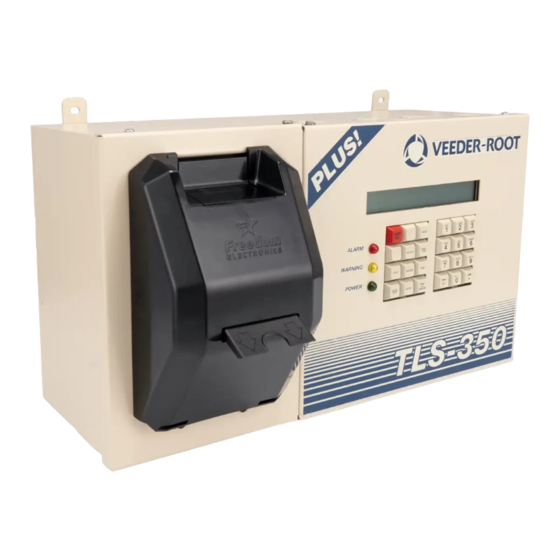
Veeder-Root TLS-350 Series Installation Manual
Sensor interface modules
Hide thumbs
Also See for TLS-350 Series:
- User manual ,
- System setup manual (227 pages) ,
- Troubleshooting manual (56 pages)
Subscribe to Our Youtube Channel
Summary of Contents for Veeder-Root TLS-350 Series
- Page 1 Manual No: 576013-813 ● Revision: D TLS-350 Series Sensor Modules Installation Guide...
- Page 2 Notice Veeder-Root makes no warranty of any kind with regard to this publication, including, but not limited to, the implied warranties of merchantability and fitness for a particular purpose. Veeder-Root shall not be liable for errors contained herein or for incidental or consequential damages in connection with the furnishing, performance, or use of this publication.
-
Page 3: Table Of Contents
Table of Contents Introduction Contractor Certification Requirements ................1 Related Manuals .......................1 Safety Precautions ......................2 Warnings and Important Notes ..................2 Installation Module/Connector Positions .....................3 Installing Modules ......................3 Connecting Sensor Wiring to Modules ................5 Figures Figure 1. CPU/ECPU Boards - Battery Backup Switch in On Position ....4 Figure 2. - Page 4 Table of Contents...
-
Page 5: Contractor Certification Requirements
• Veeder-Root Interstitial Sensor Interface Module Part No. 329358-001 (with console) The above parts are for TLS 350 Series Consoles designed and manufactured by Veeder-Root. This manual assumes all preliminary site preparation is completed, and that field wiring from the sensor junction box to the console is in place. -
Page 6: Safety Precautions
Failure to install this product in accordance with its instructions and warnings will result in the voiding of all warranties connected with this product. To help ensure proper installation and unit performance, we recommend that a Veeder-Root Authorized Service Contractor install this equipment. -
Page 7: Installation
Installation Module/Connector Positions Installing interface modules in a TLS-350 Series Console is a simple process. However, there are important points to remember: 1. For each module, a corresponding expansion slot with connector must be available. 2. ALL unused expansion slots MUST be covered with blank face plates. -
Page 8: Figure 1. Cpu/Ecpu Boards - Battery Backup Switch In On Position
TLS-350 Series Sensor Module Installation Guide Installing Modules CPU Board Battery Backup Switch (S1) Shown in ON position (up) 1 2 3 4 1 2 3 4 OPEN OPEN BATT OPEN BATT OPEN DIP switches (S2) ECPU Board DIP switches (S2) -
Page 9: Connecting Sensor Wiring To Modules
TLS-350 Series Sensor Module Installation Guide Connecting Sensor Wiring to Modules 3. Locate the IS bay in the right side of the console (Figure 2). Avoid shorting high voltage across any component or module to the intrinsically safe (IS) bay of the console. This could result in an explosion near the sensor. -
Page 10: Figure 3. Type A Interface Module Wiring Diagram
TLS-350 Series Sensor Module Installation Guide Connecting Sensor Wiring to Modules Table 1.- Maximum Sensors Per Interface Module Interface Module Number of Sensors Type A Type B Vapor Sensor Groundwater Sensor Interstitial Sensor TYPE A AND INTERSTITIAL SENSOR MODULES For Type A and Interstitial Sensor Interface Modules, connect the two marked or color-coded wires from each sensor to the appropriate terminals (see Figure 3 and Figure 4). -
Page 11: Figure 4. Interstitial Sensor Interface Module Wiring Diagram
TLS-350 Series Sensor Module Installation Guide Connecting Sensor Wiring to Modules SENSOR MAXIMUM SENSOR OUTPUT RATINGS: 15 VDC .15 AMP INTERSTITIAL SENSOR INTERFACE MODULE Attach Cable Shields to Ground Lug Closest to Conduit Entry Console Rigid Conduit (enters Console Up to 8 sensors through an I.S. -
Page 12: Figure 6. Vapor Sensor Interface Module Wiring Diagram
TLS-350 Series Sensor Module Installation Guide Connecting Sensor Wiring to Modules VAPOR MAXIMUM SENSOR V G W V G W V G W V G W V G W SENSOR OUTPUT RATINGS: 15 VDC .15 AMP VAPOR SENSOR INTERFACE MODULE... - Page 14 Veeder-Root has sales offices around the world to serve you. Headquarters 125 Powder Forest Drive Simsbury, CT 06070-7684 Tel: (860) 651-2700 Fax: (860) 651-2719 Email: marketing@veeder.com...


Need help?
Do you have a question about the TLS-350 Series and is the answer not in the manual?
Questions and answers