
Related Manuals for Veeder-Root TLS-350l


Summary of Contents for Veeder-Root TLS-350l
- Page 1 • Manual No: 577014-074 Revision: A TLS-350 To TLS-450PLUS Console Upgrade Instructions...
- Page 2 If “lost” equipment is delivered at a later date and is not needed, Veeder-Root will allow a Return to Stock without a restocking fee. Veeder-Root will NOT be responsible for any compensation when a customer chooses their own carrier.
-
Page 3: Table Of Contents
Table of Contents Introduction Contractor Certification Requirements ................1 Safety Precautions ......................1 Safety Warnings .......................2 Related Documents ......................2 Documents Required To Install Equipment ..............2 Reference Manuals ....................2 Removing The Existing Console ................3 Installing The TLS-450PLUS Console Mounting The Console ......................4 Connecting Wiring To Console Modules ................4 Installing I/O, MDIM Or LVDIM Modules ................4 Installing Comm Modules ....................5 Precautions Against Static Electricity ...............5... -
Page 4: Contractor Certification Requirements
Contractor Certification Requirements Veeder-Root requires the following minimum training certifications for contractors who will install and setup the equipment discussed in this manual: Installer Certification (Level 1): Contractors holding valid Installer Certification are approved to perform wiring and conduit routing;... -
Page 5: Safety Warnings
Introduction Safety Warnings Safety Warnings WARNING This console contains high voltages which can be lethal. It is also connected to low power devices that must be kept intrinsically safe. FAILURE TO COMPLY WITH THE FOLLOWING WARNINGS AND SAFETY PRECAUTIONS COULD CAUSE DAMAGE TO PROPERTY, ENVIRONMENT, RESULTING IN SERIOUS INJURY OR DEATH. -
Page 6: Removing The Existing Console
Removing The Existing Console The key to a successful TLS-450PLUS retrofit installation is the careful removal of the old console and wiring. The first concern is safety, so if the console is in a public area of the store, barricade off the work area to prevent injuries. -
Page 7: Installing The Tls-450Plus Console
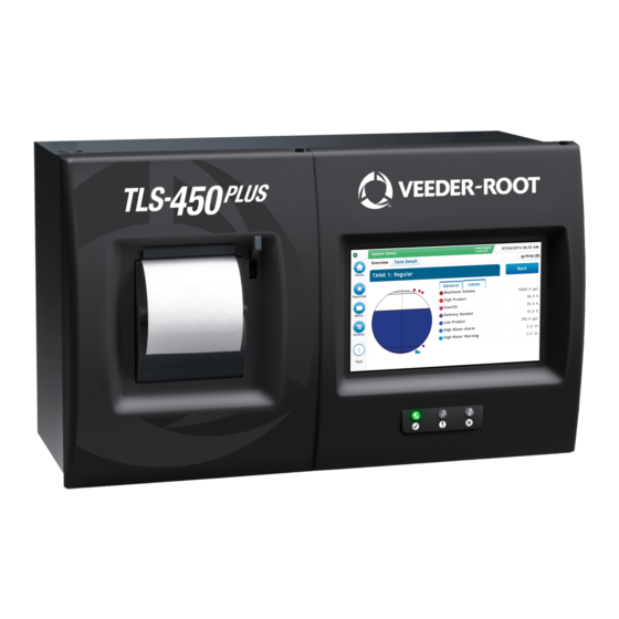
Installing The TLS-450PLUS Console Mounting The Console The TLS-450PLUS has the same mounting bolt pattern and approximate weight as the TLS-350. One major consideration for the placement of the TLS-450PLUS is that the screen is at eye level so it can be seen and touched (see Figure 1). -
Page 8: Installing Comm Modules
Installing The TLS-450PLUS Console Installing Comm Modules Installing Comm Modules PRECAUTIONS AGAINST STATIC ELECTRICITY Before removing electronic components from their antistatic bags read the following static electricity precautions. 1. Before handling any components, discharge your body's static electric charge by touching a grounded surface or using a grounding strap. -
Page 9: Figure 1. Tls-450Plus Console Dimensions And Designated Conduit Knockouts
Installing The TLS-450PLUS Console Installing Comm Modules 3-1/8'' Conduit entry for 3-1/8'' console power 3-1/8'' 3/4, 1 I.P.S. knockouts 1" 4-5/8'' 5.925'' 0.65'' Conduit entries to Module bay 3/4, 1 I.P.S. knockouts TOP VIEW (typ. 4 places) 1/2'' TYP. 16'' 1-1/8"... -
Page 10: Figure 2. Tls-450Plus Console - Plug-In Module Bays
Installing The TLS-450PLUS Console Installing Comm Modules Comm Bay Module Bay Power connector cover plate (shown removed) WARNING - HIGH VOLTAGE UNDER THIS COVER AC power input connector 120/240 Vac, 1 2 3 50/60 Hz, 2A maximum N/L2 Overfill alarm relay connector 120/240 Vac, 2A maximum... -
Page 11: Connecting The Power Wires To The Console
Installing The TLS-450PLUS Console Connecting The Power Wires To The Console Table 1. Selectable Comm Module Permissible Slots and Port Availability Slot 1 Slot 2 Slot 3 Port Port Port Comm Comm Module Type RS-232 Single Port (also EDIM, Satellite S-SAT and Satellite H-JBox apps.) RS-232 Dual Port (also EDIM, Satellite S-SAT and Satellite H-JBox apps.) -
Page 12: Figure 5. Wiring Ac Power To The Tls-450Plus Console
Installing The TLS-450PLUS Console Connecting The Power Wires To The Console 4. Next strip the ends of the power wires brought into the console. Referring to Figure 5 and to the locations printed where the power connector attaches to the console, attach the L1, panel ground and neutral wires (#14 AWG) to the connector block. -
Page 13: Initial Startup Procedure
Initial Startup Procedure After installing the TLS-450PLUS console follow the appropriate initial startup procedure below: FOR SITES WITHOUT WIRELESS 2 DEVICES 1. Power up the TLS-450PLUS and wait 5 minutes until the console’s 'Discover Mode' is complete. 2. Setup the TLS-450PLUS. FOR SITES WITH WIRELESS 2 DEVICES 1. - Page 14 For technical support, sales or other assistance, please visit: www.veeder.com...
Need help?
Do you have a question about the TLS-350l and is the answer not in the manual?
Questions and answers