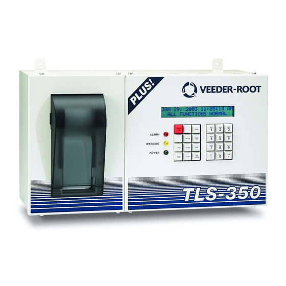
Veeder-Root TLS-3 Series Quick Start Manual

Veeder-Root TLS-3 Series Quick Start Manual

Display replacement guide
Hide thumbs Also See for TLS-3 Series:

Advertisement

Manual No: 577014-101
Revision: A
TLS-3XX Series Consoles
Display Replacement Guide

Advertisement

Table of Contents
loading
Need help?

Need help?

Do you have a question about the TLS-3 Series and is the answer not in the manual?

Questions and answers

Subscribe to Our Youtube Channel

Summary of Contents for Veeder-Root TLS-3 Series

  • Page 1 Manual No: 577014-101 ● Revision: A TLS-3XX Series Consoles Display Replacement Guide...
  • Page 2 Customer Service will work with production facility to have the replacement product shipped as soon as possible. If “lost” equipment is delivered at a later date and is not needed, Veeder-Root will allow a Return to Stock without a restocking fee.
  • Page 3: Table Of Contents

    Table of Contents Introduction Contractor Certification Requirements ................1 Safety Precautions ......................1 Before You Begin ......................2 Display Replacement Procedure ................3 Figures Figure 1. Removing the Display and Keyboard Cable Connectors ......3 Figure 2. Top Display/Keyboard Cover Securing Tabs ..........4 Figure 3. Display/Keyboard Cover Wiring Input Label Positions (330636-000 Labels Shown) ..............4 Figure 4.
  • Page 4: Contractor Certification Requirements

    • ProPlus and ProMax Contractor Certification Requirements Veeder-Root requires the following minimum training certifications for contractors who will install and setup the equipment discussed in this manual: Installer Certification (Level 1): Contractors holding valid Installer Certification are approved to perform wiring and conduit routing;...
  • Page 5: Before You Begin

    2. Remove rings from hands, metal watch bands and bracelets, and loose hanging neck jewelry before performing these procedures. 3. Do not modify or use service parts other than those provided by Veeder-Root. Before You Begin Table 1 lists the replacement parts needed for the display replacement instructions described in this manual.
  • Page 6: Display Replacement Procedure

    Display Replacement Procedure 1. Switch off, tag and lockout power to the console. Open the two front doors of the console. Disconnect the Display (1 upper) and Keyboard (2 lower) cable connectors from the consoles CPU board as shown in Figure 1.
  • Page 7: Figure 2. Top Display/Keyboard Cover Securing Tabs

    Display Replacement Procedure Before You Begin 2. Notice the two small slots in the top of the display/keyboard door. 3. Facing the inside of the display door, insert a flat blade screwdriver between the top of the plastic display/ keyboard cover and next to one of the two tabs of the cover that seat in the door’s slots (see Figure 2). Gently pry down with the screwdriver blade near the tab to free it from the slot in the door, then repeat this procedure to free the second tab.
  • Page 8: Figure 4. Removing Keyboard

    Display Replacement Procedure Before You Begin Flip the old display/keyboard assembly over (see Figure 4). The keyboard is held in place by three notched sections (item 1) along its top edge and three flex snaps (item 2) along its lower edge. Remove the keyboard assembly from the old display’s plastic cover by pressing down on the three snaps below the keyboard assembly one at a time, while rotating the bottom edge of the keyboard away from the cover (see Figure 4).
  • Page 9 For technical support, sales or other assistance, please visit: www.veeder.com...

This manual is also suitable for:

Tls-300Tls-350EmcProplusPromax

Table of Contents