
Related Manuals for Allied Telesis AT-2916LX10/LC-901


Summary of Contents for Allied Telesis AT-2916LX10/LC-901
-
Page 1: Installation Guide
Gigabit Ethernet Network Adapters AT-2916SX AT-2916LX10/LC-901 AT-2931SX AT-2972SX AT-2972LX10/LC-901 AT-2972SX/2 AT-2972T/2 Installation Guide 613-001286 Rev. B... - Page 2 Allied Telesis, Inc. reserves the right to make changes in specifications and other information contained in this document without prior written notice. The information provided herein is subject to change without notice. In no event shall Allied Telesis, Inc. be liable for any incidental, special, indirect, or consequential damages whatsoever, including but not limited to lost profits, arising out of or related to this manual or the information contained herein, even if Allied Telesis, Inc.
-
Page 3: Electrical Safety And Emissions Standards
European Union Restriction of the Use of Certain Hazardous Substances (RoHS) in Electrical and Electronic Equipment This Allied Telesis RoHS-compliant product conforms to the European Union Restriction of the Use of Certain Hazardous Substances (RoHS) in Electrical and Electronic Equipment. Allied Telesis ensures RoHS conformance by requiring... - Page 4 Electrical Safety EN60950 (TUV), UL 60950 ( Laser Safety EN60825 Translated Safety Statements Important: The indicates that a translation of the safety statement is available in a PDF document titled “Translated Safety Statements” on the Allied Telesis website at www.alliedtelesis.com/support/software.
-
Page 5: Table Of Contents
Contents Safety Symbols Used in this Document ........................12 Where to Find Web-based Guides ..........................13 Contacting Allied Telesis ...............................14 Online Support ...............................14 Email and Telephone Support..........................14 Warranty.................................14 Returning Products ..............................14 Sales or Corporate Information ..........................14 Management Software Updates..........................14 Chapter 1: Introduction to the AT-29xx Series Gigabit Ethernet Network Adapters ............15 Functional Description ..............................16... - Page 6 Contents Checksum Offload ..............................66 VLAN ID .................................67 Wake Up Capabilities .............................68 WOL Speed ................................69 Chapter 6: Installing the Linux Driver Software ........................71 Installing the Linux Driver Software ..........................72 Building a Driver from a TAR File ...........................72 Network Installation ...............................74 Removing the Linux Driver from a TAR Installation.......................75 Module Parameters ...............................76 Chapter 7: Installing the Novell NetWare Driver Software ....................83 Driver Installation ................................84...
- Page 7 AT-7100/24 Fast Ethernet Switch Installation Guide Appendix B: Cleaning Fiber Optic Connectors 135 Using a Cartridge-Type Cleaner136 Using a Swab138...
- Page 8 Contents...
- Page 9 Figures Figure 1. Removing the PC Cover............................25 Figure 2. Removing the Faceplate From PCI Slot .......................26 Figure 3. Inserting the Network Adapter Card ........................27 Figure 4. Securing the Adapter Card ...........................28 Figure 5. Welcome to the Found New Hardware Wizard Window..................33 Figure 6.
- Page 10 Figures...
- Page 11 Gigabit Ethernet Network adapters. In addition, procedures are provided that describe how to install and configure the driver software. The Preface contains the following sections: “Safety Symbols Used in this Document” on page 12 “Where to Find Web-based Guides” on page 13 “Contacting Allied Telesis” on page 14...
-
Page 12: Safety Symbols Used In This Document
Preface Safety Symbols Used in this Document This document uses the safety symbols defined in Table 1. Table 1. Safety Symbols Symbol Meaning Description Caution Performing or omitting a specific action may result in equipment damage or loss of data. Warning Performing or omitting a specific action may result in electrical shock. -
Page 13: Where To Find Web-Based Guides
AT-29xx Series Gigabit Ethernet Network Adapters Installation Guidee Where to Find Web-based Guides The installation and user guides for all Allied Telesis products are available in portable document format (PDF) on our web site at www.alliedtelesis.com/support/software. You can view the documents... -
Page 14: Contacting Allied Telesis
Allied Telesis web site: www.alliedtelesis.com/support/software Allied Telesis FTP server: ftp://ftp.alliedtelesis.com If you prefer to download new software from the Allied Telesis FTP server from your workstation’s command prompt, you will need FTP client software and you must log in to the server. Enter “anonymous” for the user... -
Page 15: Chapter 1: Introduction To The At-29Xx Series Gigabit Ethernet Network Adapters
Chapter 1 Introduction to the AT-29xx Series Gigabit Ethernet Network Adapters This chapter provides an introduction to the Allied Telesis AT-29xx Series Gigabit Ethernet Network adapters and contains the following sections: “Functional Description” on page 16 “LEDs” on page 18 “AT-29xx Series Adapter Software Drivers”... -
Page 16: Functional Description
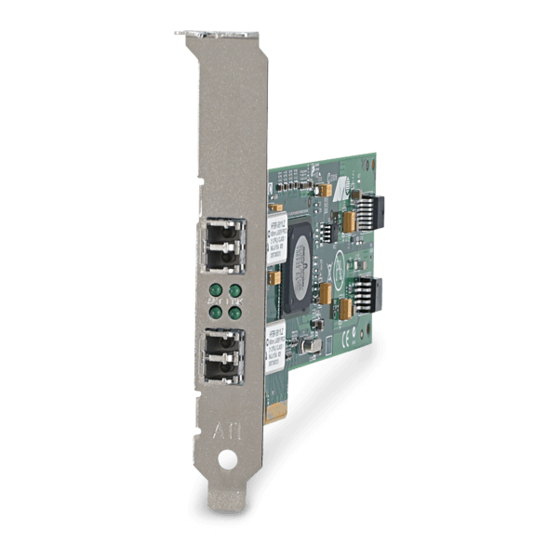
The AT-2916 adapter is a 33/66Mhz 32-bit interface (PCI) card and is available in three versions: AT-2916SX/SC adapter AT-2916SX/LC adapter AT-2916LX10/LC-901 adapter (suitable for long-haul fiber optic cables) The AT-2931SX adapter is a 33/66/133Mhz 32/64-bit interface (PCI-X) card and is available in two versions:... -
Page 17: Contents Of Your Shipment
AT-29xx Series Gigabit Ethernet Network Adapters Installation Guide The adapter versions differ only in their PCI connector type. The SC version adapters have an SC connector, and the LC version adapters have an LC connector. The LEDs and software drivers are identical for all adapter models and versions. -
Page 18: Leds
Chapter 1: Introduction to the AT-29xx Series Gigabit Ethernet Network Adapters LEDs All fiber adapter models have two LEDs: LINK and ACT. The LINK LED indicates an active link and the ACT (Activity) LED indicates data transfer status. After the driver is loaded and the cables are connected properly. The LINK LED is lit and the ACT LED is on if data traffic is present. -
Page 19: At-29Xx Series Adapter Software Drivers
29xx software driver from the Microsoft’s Update Manager. This utility is accessed through the Start button. However, the Microsoft Update Manager may not have the latest Allied Telesis software drivers. You can download the latest version of the software driver from the Allied Telesis website at www.alliedtelesis.com/support/software. -
Page 20: Failover Teaming
The AT-29xx Series adapters have advanced server features for teaming and failover. For more information, see the Broadcom Advanced Control Suite 3 User’s Guide which you can download from the Allied Telesis website at www.alliedtelesis.com/support/software. Note Allied Telesis recommends disabling STP when using the teaming and fault tolerance features. -
Page 21: Chapter 2: Installing The Hardware
Chapter 2 Installing the Hardware The AT-29xx Series adapters can be installed in a server or a workstation. This chapter describes how to install the adapters. This chapter contains the following sections: “Reviewing Safety Precautions” on page 22 “Pre-Installation Checklist” on page 24 “Installing a Network Adapter Card”... -
Page 22: Reviewing Safety Precautions
Note indicates that a translation of the safety statement is available in a PDF document titled “Translated Safety Statements” on the Allied Telesis website at www.alliedtelesis.com/support/ software. Warning This is a “Class 1 LED product”. Warning Do not stare into the laser beam. - Page 23 AT-29xx Series Gigabit Ethernet Network Adapters Installation Guide Warning The adapter is being installed in a system that operates with voltages that can be lethal. Before you remove the cover of your system, you must observe the following precautions to protect yourself and to prevent damage to the system components.
-
Page 24: Pre-Installation Checklist
6. Check the adapter for visible signs of damage, particularly on the card’s edge connector. Never attempt to install any damaged adapter. If the adapter is damaged, report it to Allied Telesis. See “Contacting Allied Telesis” on page 14. -
Page 25: Installing A Network Adapter Card
AT-29xx Series Gigabit Ethernet Network Adapters Installation Guide Installing a Network Adapter Card The following instructions apply to installing an AT-29xx Series Gigabit Ethernet Network adapter in most systems. Refer to the manuals that were supplied with your system for details about performing these tasks on your particular system. -
Page 26: Figure 2. Removing The Faceplate From Pci Slot
Chapter 2: Installing the Hardware 3. Select an empty, non-shared PCI slot and remove the faceplate. Keep the faceplate in a safe place. You may need it for future use. See Figure 2. Figure 2. Removing the Faceplate From PCI Slot Note If you cannot locate or know how to find an appropriate PCI slot, refer to the documentation that came with your system. -
Page 27: Figure 3. Inserting The Network Adapter Card
AT-29xx Series Gigabit Ethernet Network Adapters Installation Guide Make sure the card is securely seated. See Figure 3. Figure 3. Inserting the Network Adapter Card Note The connector dock in a 32-bit PCI slot is shorter than in a 64-bit PCI slot. -
Page 28: Figure 4. Securing The Adapter Card
Chapter 2: Installing the Hardware 6. Secure the network adapter card to the chassis with a Phillips-head screw (not provided) as shown in Figure 4. Figure 4. Securing the Adapter Card 7. Replace the system’s cover and secure it with the screws removed in Step 2. -
Page 29: Connecting The Network Cables
AT-29xx Series Gigabit Ethernet Network Adapters Installation Guide Connecting the Network Cables All the fiber Gigabit Ethernet network adapters have two fiber optic connectors for attaching the system to a compatible link partner, or an IEEE 802.3z compliant gigabit switch. After connecting the system to the network and power is supplied, the adapter performs auto-negotiation and attempts to establish the connection at 1000 Mbps full-duplex only. -
Page 30: Warranty Registration
Allied Telesis hardware products are covered under limited warranties. Some products have a longer coverage than others. All Allied Telesis warranties are subject to and provided only on the terms and conditions set out in the Allied Telesis Limited Warranties listed on the... -
Page 31: Chapter 3: Installing Windows Server 2003 And Windows Xp Driver Software
Chapter 3 Installing Windows Server 2003 and Windows XP Driver Software This chapter describes how to install the Windows Server 2003 and Windows XP driver software. This chapter contains the following sections: “Installing the Driver Software” on page 32 “Uninstalling the Driver Software” on page 41 After you install the driver software, you can modify the configuration properties as described in see Chapter 5, “Setting Advanced Properties”... -
Page 32: Installing The Driver Software
Installing the Driver Software When a Windows Server 2003 or Windows XP system first boots up after installing a new Allied Telesis Gigabit Ethernet adapter, the system automatically detects the new hardware and prompts you to install the driver software for that device. -
Page 33: Figure 5. Welcome To The Found New Hardware Wizard Window
AT-29xx Series Gigabit Ethernet Network Adapters Installation Guide To install the adapter software on a Windows Server 2003 or Windows XP system, do the following: 1. Click Install from a list or specific location (Advanced). Figure 5. Welcome to the Found New Hardware Wizard Window 2. -
Page 34: Figure 6. Found New Hardware Wizard Window: Search And Installation Options
Chapter 3: Installing Windows Server 2003 and Windows XP Driver Software Figure 6. Found New Hardware Wizard Window: Search and Installation Options 3. Click Include this location in the search. 4. Click Browse and locate the path of the software driver. 5. -
Page 35: Updating The Adapter Software
Windows Server 2003 or Windows XP systems. To obtain the latest Adapter Software version of an AT-29xx Series adapter software drivers, download it from the Allied Telesis website at www.alliedtelesis.com/support/software. Note You may need to reboot your system after completing the driver update to properly load the new drivers. -
Page 36: Figure 7. Windows Server 2003 Start Window
Chapter 3: Installing Windows Server 2003 and Windows XP Driver Software Figure 7. Windows Server 2003 Start Window 3. Select Run from the menu and enter the following command: devmgmt.msc See Figure 8 for an example of the Run Window. Figure 8. -
Page 37: Figure 9. Device Manager Window (Network Adapter Folder Is Collapsed)
AT-29xx Series Gigabit Ethernet Network Adapters Installation Guide The Device Manager Window is shown in Figure 9. Figure 9. Device Manager Window (Network adapter folder is collapsed) 4. In the Device Manager window, click the + next to the Network adapters folder. -
Page 38: Figure 10. Welcome To Hardware Update Wizard Window
Chapter 3: Installing Windows Server 2003 and Windows XP Driver Software The Hardware Update Wizard Window opens, as shown in Figure 10. Figure 10. Welcome to Hardware Update Wizard Window 6. For a Windows Server 2003 system, skip to step 10. For a Windows XP system, click No, not this time to copy the driver software from your PC. -
Page 39: Modifying Configuration Properties
AT-29xx Series Gigabit Ethernet Network Adapters Installation Guide 8. Click Install from a list or specified location (Advanced). 9. Click Next. 10. If you are prompted to specify the location of the software driver, click Browse (do not use the text field) and locate the path. After you install the driver software, you can modify the configuration properties. -
Page 40: Figure 12. System Properties Dialog Box
Chapter 3: Installing Windows Server 2003 and Windows XP Driver Software Figure 12. System Properties Dialog Box For instructions that describe how to set the Advanced Properties, see Chapter 5, “Setting Advanced Properties” on page 53. -
Page 41: Uninstalling The Driver Software
Before physically removing an adapter from your system, you must uninstall the adapter driver software. Caution Before uninstalling the Allied Telesis device, be sure to capture all Advanced Property settings because the properties are lost during the uninstall process. To uninstall the adapter software from your system, perform the following procedure: 1. - Page 42 Chapter 3: Installing Windows Server 2003 and Windows XP Driver Software...
-
Page 43: Chapter 4: Installing The Windows 2008 R2, Windows Vista, And Windows 7 Driver Software
Chapter 4 Installing the Windows 2008 R2, Windows Vista, and Windows 7 Driver Software This chapter describes how to install the Windows 2008 R2, Windows Vista, and Windows 7 driver software on an AT-29xx Series adapter. The installation procedures are identical for both the 32-bit and 64-bit Windows Operating Systems. -
Page 44: Installing The Driver Software
Chapter 4: Installing the Windows 2008 R2, Windows Vista, and Windows 7 Driver Software Installing the Driver Software After you install an AT-29xx Series adapter, the system detects the new hardware and creates an entry in the Device Manager when the Windows operating system first boots up. -
Page 45: Figure 13. Windows 2008 R2 And Windows 7 Search Box
AT-29xx Series Gigabit Ethernet Network Adapters Installation Guide Figure 13. Windows 2008 R2 and Windows 7 Search Box 2. Enter the following command: mmc compmgmt.msc The Device Manager window is displayed. For an example of the Device Manager window, see Figure 9 on page 37. -
Page 46: Figure 14. Windows Vista Start Menu
Chapter 4: Installing the Windows 2008 R2, Windows Vista, and Windows 7 Driver Software Selecting the Device Manager in Windows Vista To select the Device Manager in the Windows Vista Operating System, do the following: 1. Select the Start menu. See Figure 14 for an example of the Windows Vista Start menu. -
Page 47: Figure 16. Device Manager Window
The Device Manager window is displayed. See Figure 16 on page 47. On the Device Manager window, “Allied Telesis AT-2972SX Gbps Fiber Ethernet” is listed under “Network adapters.” The Device Manager window for an AT-2972SX adapter is shown in Figure 16. -
Page 48: Installing The Windows 2008 R2, Windows, Vista, And Windows 7 Driver Software
Chapter 4: Installing the Windows 2008 R2, Windows Vista, and Windows 7 Driver Software Installing the To obtain the latest version of an AT-29xx Series adapter software drivers, download it from the Allied Telesis website at www.alliedtelesis.com/ Windows 2008 support/software. -
Page 49: Figure 18. Update Driver Software - Ethernet Controller Window
AT-29xx Series Gigabit Ethernet Network Adapters Installation Guide The Update Driver Software - Ethernet Controller Window is displayed. See Figure 18. Figure 18. Update Driver Software - Ethernet Controller Window 5. Click Browse my computer for driver software. The Update Driver Software - Ethernet Controller: Browse for Driver Software Window is displayed. -
Page 50: Figure 19. Update Driver Software: Ethernet Controller: Browse
Chapter 4: Installing the Windows 2008 R2, Windows Vista, and Windows 7 Driver Software 6. Click Browse to search your computer for the location of the driver software. See Figure 19. Figure 19. Update Driver Software: Ethernet Controller: Browse 7. Click Next. A confirmation message is displayed. See Figure 20. Figure 20. -
Page 51: Uninstalling The Driver Software
You must have Administrator privileges to remove the driver software. Caution Before uninstalling the Allied Telesis device, be sure to capture all of the Advanced Property settings because the properties are lost during the uninstall process. To uninstall the driver software from your system, do the following: 1. - Page 52 Chapter 4: Installing the Windows 2008 R2, Windows Vista, and Windows 7 Driver Software Note Not all of the driver files are removed as a result of this procedure. You can remove additional drivers and installation files by selecting the checkbox to remove these files.
-
Page 53: Chapter 5: Setting Advanced Properties
Chapter 5 Setting Advanced Properties The Windows Advanced Properties are accessible from the Advanced Tab. For Windows Server 2003 and Windows XP systems, you access the Advanced Tab through the System Properties Dialog Box. For the Windows 2008 R2, Windows Vista, and Windows 7 Operating System software, you access the Advanced Tab through the Device Manager. -
Page 54: Opening Advanced Properties
Chapter 5: Setting Advanced Properties Opening Advanced Properties In most cases, the default property values available on the Advanced Tab are appropriate although you can change any of the available options to meet the requirements of your system. You must have Administrator privileges to modify the driver software. -
Page 55: Qos
AT-29xx Series Gigabit Ethernet Network Adapters Installation Guide 802.1p QOS The 802.1p QOS property is a standard that enables Quality of Service (QOS). It is responsible for the QOS provisions on the local segment, and the avoidance of the “all packets are treated equally” issue, which falls onto the hub or switch servicing segment. -
Page 56: Figure 21. Advanced Tab
Chapter 5: Setting Advanced Properties Figure 21. Advanced Tab 3. From the Properties list, select 802.1p QOS. 4. From the Values list, select one of the following: Enable - Enables the 802.1p QOS property. Disable - Disables the 802.1p QOS property. This is the default. Note Enabling 802.1p QOS requires an 802.1p-aware switch. -
Page 57: Flow Control
AT-29xx Series Gigabit Ethernet Network Adapters Installation Guide Ethernet@Wire- The Ethernet@Wirespeed property enables a Gigabit Ethernet adapter to establish a link at a lower speed when only two pairs of wires are available speed ™ in the cabling plant. This property is available on the AT-2972/T2 adapter (AT-2972/T2 only. -
Page 58: Jumbo Mtu
Chapter 5: Setting Advanced Properties To change the Flow Control property, do the following: 1. For Windows Server 2003 and Windows XP systems, access the System Properties Dialog Box. See “Modifying Configuration Properties” on page 39. For Windows 2008 R2, Windows 7, and Windows Vista systems, access the Device Manger for your operating system: To access the Device Manager window in Windows 2008 R2 or Windows 7, see “Selecting the Device Manager in Windows 2008... -
Page 59: Interrupt Moderation
AT-29xx Series Gigabit Ethernet Network Adapters Installation Guide To increase the size of the received frames, do the following: 1. For Windows Server 2003 and Windows XP systems, access the System Properties Dialog Box. See “Modifying Configuration Properties” on page 39. For Windows 2008 R2, Windows 7, and Windows Vista systems, access the Device Manger for your operating system: To access the Device Manager window in Windows 2008 R2 or... -
Page 60: Ipsec Offload
Vista’s advanced IPSec and Firewall features as well as their implementation. These topics are beyond the scope of this chapter. Instead, Allied Telesis recommends that you consult Technet for additional information. By default, the IPSec Offload property is set to Disabled. -
Page 61: Large Send Offload Property
AT-29xx Series Gigabit Ethernet Network Adapters Installation Guide Note The IPSec Offload feature applies only to Windows Vista and Windows 7. To change the IPSec Offload setting, do the following: 1. For Windows Server 2003 and Windows XP systems, access the System Properties Dialog Box. -
Page 62: Network Address
Chapter 5: Setting Advanced Properties To change the Large Send Offload property, do the following: 1. For Windows Server 2003 and Windows XP systems, access the System Properties Dialog Box. See “Modifying Configuration Properties” on page 39. For Windows 2008 R2, Windows 7, and Windows Vista systems, access the Device Manger for your operating system: To access the Device Manager window in Windows 2008 R2 or Windows 7, see “Selecting the Device Manager in Windows 2008... -
Page 63: Priority & Vlan
AT-29xx Series Gigabit Ethernet Network Adapters Installation Guide To change the Network Address property, do the following: 1. For Windows Server 2003 and Windows XP systems, access the System Properties Dialog Box. See “Modifying Configuration Properties” on page 39. For Windows 2008 R2, Windows 7, and Windows Vista systems, access the Device Manger for your operating system: To access the Device Manager window in Windows 2008 R2 or Windows 7, see “Selecting the Device Manager in Windows 2008... -
Page 64: Receive Side Scaling
Chapter 5: Setting Advanced Properties For Windows 2008 R2, Windows 7, and Windows Vista systems, access the Device Manger for your operating system: To access the Device Manager window in Windows 2008 R2 or Windows 7, see “Selecting the Device Manager in Windows 2008 R2 and Windows 7”... -
Page 65: Speed & Duplex Mode
AT-29xx Series Gigabit Ethernet Network Adapters Installation Guide 2. Click the Advanced tab. The Advanced tab is shown in Figure 21 on page 56. 3. From the Property list on the Advanced tab, select “Receive Side Scaling.” 4. In the Value list on the Advanced tab, select one of the following: Enabled Disabled 5. -
Page 66: Checksum Offload
Chapter 5: Setting Advanced Properties 100 Mb Full 100 Mb Half Auto 5. Click OK. 6. If prompted to restart your computer, click Yes. Although it is not necessary to reboot the system for new adapter properties to take effect, rebooting is recommended to reinitialize all registers. -
Page 67: Vlan Id
AT-29xx Series Gigabit Ethernet Network Adapters Installation Guide 5. Click OK. 6. If prompted to restart your computer, click Yes. Although it is not necessary to reboot the system for new adapter properties to take effect, rebooting is recommended to reinitialize all registers. -
Page 68: Wake Up Capabilities
AT-2972T/4 WOL is not supported on fiber NIC cards due to power limitations of the PCI bus. The Gigabit fiber cards in this category are: AT-2916SX AT-2916LX10/LC-901 AT-2931SX,AT-2972SX AT-2972LX10/LC-901 AT-2972SX/2 To change the Wake Up Capabilities property, do the following: 1. -
Page 69: Wol Speed
AT-29xx Series Gigabit Ethernet Network Adapters Installation Guide and allows the network adapter to wake up the system when an event, such as a ping or an ARP request, is received. 5. Click OK. WOL Speed The WOL Speed property sets the speed at which the network adapter connects to the network while the adapter is in Wake on LAN (WOL) mode. - Page 70 Chapter 5: Setting Advanced Properties 7. Verify that the adapter port LEDs operate as described in “LEDs” on page 18.
-
Page 71: Chapter 6: Installing The Linux Driver Software
Chapter 6 Installing the Linux Driver Software This chapter describes the Linux driver for the AT-29xx Series Gigabit Ethernet Network adapters and includes the following sections: “Installing the Linux Driver Software” on page 72 “Network Installation” on page 74 “Removing the Linux Driver from a TAR Installation” on page 75 “Module Parameters”... -
Page 72: Installing The Linux Driver Software
Removing the tg3 Driver Many various Linux distributions may load the native tg3 driver by default for the Allied Telesis Gigabit Ethernet Network adapters. It may be necessary to unload the native tg3 driver first, before installing the tg3.o driver from this installation. - Page 73 AT-29xx Series Gigabit Ethernet Network Adapters Installation Guide Although tg3 is a fully functioning driver, Allied Telesis recommends that you use the newer tg3 driver provided by Allied Telesis. Use ifconfig to bring down all eth# interfaces used by tg3 and enter the following...
-
Page 74: Network Installation
Chapter 6: Installing the Linux Driver Software Network Installation For network installations through NFS, FTP, or HTTP (using a network boot disk or PXE), a driver diskette that contains the tg3 driver may be needed. The driver diskette images for the most recent Red Hat versions are included. -
Page 75: Removing The Linux Driver From A Tar Installation
AT-29xx Series Gigabit Ethernet Network Adapters Installation Guide Removing the Linux Driver from a TAR Installation If the driver was installed using make install from the tar file, you must manually delete the tg3.o driver. -
Page 76: Module Parameters
Chapter 6: Installing the Linux Driver Software Module Parameters Optional parameters for the driver can be supplied as command line arguments to the insmod command. Typically, these parameters are set in the file /etc/modules.conf (see the man page for modules.conf). These parameters take the following form: <parameter>... - Page 77 AT-29xx Series Gigabit Ethernet Network Adapters Installation Guide Note This parameter is ignored and assumed to be 1 if the line_speed parameter is set to 0. full_duplex This parameter is used together with line_speed to select the speed and duplex mode of the link. Note that this parameter is ignored if line_speed is 0.
- Page 78 Chapter 6: Installing the Linux Driver Software Enables jumbo frames up to the specified MTU size. The valid range for this parameter is 1500 to 9000. The default is 1500 which is the standard Ethernet (non-jumbo) MTU size. Note that the MTU size excludes the Ethernet header size of 14 bytes.
- Page 79 AT-29xx Series Gigabit Ethernet Network Adapters Installation Guide Setting this parameter higher allows the NIC to buffer larger bursts of network traffic without dropping frames, especially on slower systems. Note that the driver may not be able to allocate the required amount of memory if this parameter is set too high.
- Page 80 Chapter 6: Installing the Linux Driver Software rx_max_coalesce_frames Configures the number of received frames before the NIC generates receive interrupt. The valid range is from 0 to 100 and the default is 15. This parameter and rx_coalesce_ticks cannot both have a value of 0. If both parameters are set to 0, no receive interrupts are generated.
- Page 81 AT-29xx Series Gigabit Ethernet Network Adapters Installation Guide enable_tso Enables or disables TCP Segmentation Option (TSO) when using kernels that support it. Choose from the following selections: – TSO disabled (default) – TSO enabled...
- Page 82 Chapter 6: Installing the Linux Driver Software...
-
Page 83: Chapter 7: Installing The Novell Netware Driver Software
Chapter 7 Installing the Novell NetWare Driver Software This chapter provides procedures for installing the Novell NetWare driver software and contains the following sections: “Driver Installation” on page 84 “Pre-Installation Requirements” on page 85 “Installing Novell NetWare Server 5.x or 6.0 Driver Software” on page 86 “Verifying or Modifying Adapter Parameters”... -
Page 84: Driver Installation
You can download the latest version of the software driver from the Allied Telesis website at www.alliedtelesis.com/ support/software. A commonly used method to install a driver on a NetWare server running... -
Page 85: Pre-Installation Requirements
“Installing the Hardware” on page 21. To enable the Allied Telesis AT-29xx Series Gigabit Ethernet network adapters to function correctly, you need to install the latest Novell NetWare support pack files. -
Page 86: Installing Novell Netware Server 5.X Or 6.0 Driver Software
In addition, you can download the latest version of the software driver from the Allied Telesis website at www.alliedtelesis.com/support/ software To install the Novell NetWare Server 5.x or 6.0 driver software, perform the following procedure: 1. - Page 87 AT-29xx Series Gigabit Ethernet Network Adapters Installation Guide 11. 5.x or 6.05.x or 6.0 NetWare 5.x or 6.0 has been successfully installed, set the minimum packet receive buffers parameter in the startup.ncf file to 1500 for each adapter in the system. Set the maximum packet receive buffers to three times the minimum packet receive buffers.
-
Page 88: Verifying Or Modifying Adapter Parameters
Chapter 7: Installing the Novell NetWare Driver Software Verifying or Modifying Adapter Parameters When an adapter configuration is saved, the NetWare install program adds load and bind statements to the autoexec.ncf file. By accessing this file, you can verify the parameters configured for each adapter, modify them, or enter additional parameters. - Page 89 AT-29xx Series Gigabit Ethernet Network Adapters Installation Guide TxPacketsPer= This is to enable the use of allowing an interrupt to occur after a specific amount of packets are transmitted. Min = 0, disabled Max = 100 Default is 20 RxPacketsPer= This is to enable the use of allowing an interrupt to occur after a specific amount of packets are received.
- Page 90 Chapter 7: Installing the Novell NetWare Driver Software FRAME= This is a Novell NetWare keyword. String specifying the frame type. Choices are: ETHERNET_II ETHERNET_802.3 ETHERNET_802.2 ETHERNET_SNAP Default value is ETHERNET_802.2 SLOT= This is a Novell NetWare keyword. System-wide unique Hardware Instance Number (HIN) that may be the physical slot number on a slot based bus such as PCI.
- Page 91 AT-29xx Series Gigabit Ethernet Network Adapters Installation Guide The Default is spurious fix = 1 (spurious fix is on). Choices are: Spuriousfix=0 Spuriousfix=1 (default). Poll= To disable interrupt driven mode in the driver set Poll=1 and the driver will not use interrupts, but will be polled by the NetWare OS.
- Page 92 Chapter 7: Installing the Novell NetWare Driver Software Note If you modify any adapter parameters, you must reboot the system before the changes take effect. If you make changes and do not reboot, you may experience configuration problems. A valid autoexec.ncf file is shown below. One set of load and bind commands (in bold) is added for each frame type the adapter is configured to support.
-
Page 93: Removing Drivers From Autoexec.ncf
AT-29xx Series Gigabit Ethernet Network Adapters Installation Guide Removing Drivers from Autoexec.ncf To remove the drivers from the Autoexec.ncf, locate the Load and Bind command lines associated with the Broadcom driver and remark them out by inserting the # symbol at the beginning of each command line, or by deleting the statement. - Page 94 Chapter 7: Installing the Novell NetWare Driver Software...
-
Page 95: Chapter 8: Installing The Ndis2 Driver Software For Ms-Dos Platforms
Chapter 8 Installing the NDIS2 Driver Software for MS-DOS Platforms This chapter provides procedures for installing the NDIS2 driver software. and contains the following sections: “Installing the NDIS2 Driver Software for Use on MS-DOS Platforms” on page 96 “Using Keywords for the B57.dos Drivers” on page 101... -
Page 96: Installing The Ndis2 Driver Software For Use On Ms-Dos Platforms
You can run the NDIS2 driver software from an MS-DOS startup disk using Microsoft Network Client 3.0. Pre-Installation Before you can successfully install the NDIS2 driver software, the Allied Telesis AT-29xx Series Gigabit Ethernet Network adapter must be Requirements physically installed in the computer. Modifying the... - Page 97 AT-29xx Series Gigabit Ethernet Network Adapters Installation Guide BINDINGS=MS$NE2CLONE LANABASE=0 Example Protocol.ini for IPX [network.setup] version=0x3110 netcard=ms$ne2clone,1,MS$NE2CLONE,1 transport=ms$ndishlp,MS$NDISHLP transport=ms$nwlink,MS$NWLINK lana0=ms$ne2clone,1,ms$nwlink lana1=ms$ne2clone,1,ms$ndishlp [MS$NE2CLONE] DriverName=B57$ [protman] DriverName=PROTMAN$ PRIORITY=MS$NDISHLP [MS$NDISHLP] DriverName=ndishlp$ BINDINGS=ms$ne2clone [ms$nwlink] DriverName=nwlink$ FRAME=Ethernet_802.2 BINDINGS=MS$NE2CLONE LANABASE=0 Example Protocol.ini for NetBEUI [network.setup] version=0x3110 netcard=ms$ne2clone,1,MS$NE2CLONE,1 transport=ms$ndishlp,MS$NDISHLP transport=ms$netbeui,MS$NETBEUI...
- Page 98 Chapter 8: Installing the NDIS2 Driver Software for MS-DOS Platforms lana0=ms$ne2clone,1,ms$ndishlp lana1=ms$ne2clone,1,ms$netbeui [MS$NE2CLONE] DriverName=B57$ [protman] DriverName=PROTMAN$ PRIORITY=MS$NDISHLP [MS$NDISHLP] DriverName=ndishlp$ BINDINGS=MS$NE2CLONE [MS$NETBEUI] DriverName=netbeui$ SESSIONS=10 NCBS=12 BINDINGS=MS$NE2CLONE LANABASE=0 2. Edit A:\Net\System.ini. a. Change netcard= to netcard=b57.dos. b. Check for references to C:\NET and change C:\NET to A:\NET if necessary.
- Page 99 AT-29xx Series Gigabit Ethernet Network Adapters Installation Guide reconnect=yes dospophotkey=N lmlogon=0 logondomain= preferredredir=basic autostart=basic maxconnections=8 [network drivers] netcard=B57.dos transport=ndishlp.sys,*netbeui devdir=A:\NET LoadRMDrivers=yes 3. Copy B57.dos to A:\Net. 4. Create the appropriate Autoexec.bat file in drive A for the chosen protocol as shown below. For TCP/IP path=a:\net a:\net\net initialize...
- Page 100 Chapter 8: Installing the NDIS2 Driver Software for MS-DOS Platforms A:\NET\NET START BASIC net use z: \\SERVERNAME\SHARENAME For NetBEUI SET PATH=A:\NET A:\NET\NET START BASIC net use z: \\SERVERNAME\SHARENAME 5. Create a Config.sys file on the startup disk in drive A as shown below. files=30 device=a:\net\ifshlp.syslastdrive=z...
-
Page 101: Using Keywords For The B57.Dos Drivers
AT-29xx Series Gigabit Ethernet Network Adapters Installation Guide Using Keywords for the B57.dos Drivers The Protocol.ini file contains certain keywords that are used by the B57.dos drivers. These keywords are listed below: BusNum. Specifies the PCI bus number on which the network controller is located. - Page 102 Chapter 8: Installing the NDIS2 Driver Software for MS-DOS Platforms...
-
Page 103: Chapter 9: Installing The Pxe Boot Agent
Chapter 9 Installing the PXE Boot Agent This chapter describes the PXE Boot Agent and provides procedures for installing it on a server running Windows Server 2003, Windows XP, DOS UNDI/APITEST, or Red Hat Linux system. This chapter contains the following sections: “Overview”... -
Page 104: Overview
Chapter 9: Installing the PXE Boot Agent Overview The Allied Telesis AT-29xx Series Gigabit Ethernet network adapters provide PXE (Preboot Execution Environment) support. PXE is enabled by default. To enable or disable PXE, refer to the b57udiag.pdf document located in the diagnostics directory. -
Page 105: Server Setup
Windows Server The current version of Windows Server 2003 does not include network drivers for the Allied Telesis Gigabit Ethernet adapters. To do remote 2003 and installation with PXE, include a network driver for the adapter as a part of Windows XP the client's installation image on the server. - Page 106 Chapter 9: Installing the PXE Boot Agent...
-
Page 107: Chapter 10: Troubleshooting
Chapter 10 Troubleshooting This chapter describes troubleshooting procedures and contains the following sections: “Hardware Diagnostics” on page 108 “Checking Port LEDs on the Adapter” on page 109 “Troubleshooting Checklist” on page 110 “Verifying the Correct Drivers are Loaded” on page 111 “Testing Network Connectivity”... -
Page 108: Hardware Diagnostics
Chapter 10: Troubleshooting Hardware Diagnostics Loopback diagnostic tests are available for testing the adapter hardware under Windows. These tests provide access to the adapter's internal or external diagnostics, where packet information is transmitted across the physical link. -
Page 109: Checking Port Leds On The Adapter
AT-29xx Series Gigabit Ethernet Network Adapters Installation Guide Checking Port LEDs on the Adapter The adapter has two LEDs: LINK and ACT. The LINK LED indicates an active link and the ACT (Activity) LED indicates data transfer status. Once the driver is loaded and the cables are connected properly. The LINK LED is lit and the ACT LED is on if data traffic is present. -
Page 110: Troubleshooting Checklist
Chapter 10: Troubleshooting Troubleshooting Checklist The following checklist provides recommended actions to take to resolve problems installing the Allied Telesis AT-29xx Series Gigabit Ethernet Network adapter or running it in your system. Warning Before opening the cabinet of your system for removing or inserting the adapter, please review all precautions outlined under “Reviewing... -
Page 111: Verifying The Correct Drivers Are Loaded
AT-29xx Series Gigabit Ethernet Network Adapters Installation Guide Verifying the Correct Drivers are Loaded The following section describes how to check if the correct drivers are loaded for NetWare and Linux. NetWare To verify that the NetWare driver software is loaded correctly, perform the following procedure. -
Page 112: Testing Network Connectivity
Chapter 10: Troubleshooting Testing Network Connectivity The following section describes how to test network connectivity for Windows Server 2003, NetWare, and Linux networks. Note When using forced link speeds, make sure that both the adapter and the switch are forced to the same speed. Or, make sure at least one link partner is configured for Auto-Negotiation. -
Page 113: Figure 23. Command Window With Pconfig/All Displayed
AT-29xx Series Gigabit Ethernet Network Adapters Installation Guide Figure 23. Command Window with pconfig/all displayed 4. Type ping <IP address> from the command line, then press Enter. The network connectivity information is displayed, as shown in Figure 24. Figure 24. Command Window with ping displayed... -
Page 114: Netware
Chapter 10: Troubleshooting NetWare To ping an IP host on the network to verify a connection has been established, perform the following procedure. 1. From the command line, type ping <IP address>, then press Enter. This command displays the packet send/receive status. Linux To verify that the Ethernet interface is up and running, run ifconfig to check the status of the Ethernet interface. -
Page 115: Software Problems And Solutions
AT-29xx Series Gigabit Ethernet Network Adapters Installation Guide Software Problems and Solutions Microsoft Remote Problem: Microsoft Remote Installation Service (RIS) installation fails for Windows XP. Installation Service (RIS) Solution: Refer to Microsoft Article Q246184, "How to Add Third-Party Instructions OEM Network Adapters to RIS Installations." Windows XP Image To deploy a Windows XP Image, follow the steps in the Microsoft Article Q246184 at... - Page 116 Chapter 10: Troubleshooting Solution: This is because some of the older servers are advertising themselves as PCI-X capable systems. This causes the adapter to operate in PCI-X mode; therefore; it is not seen by the PCI bus. This problem can be corrected by configuring the firmware to operate in forced pci mode.
-
Page 117: Chapter 11: Dos Diagnostics
Chapter 11 DOS Diagnostics This chapter describes the DOS diagnostics and contains the following sections: “Introduction” on page 118 “DOS Prompt Commands” on page 119 “Diagnostic Tests” on page 120 “Error Messages” on page 127... -
Page 118: Introduction
Chapter 11: DOS Diagnostics Introduction This chapter describes how to use the DOS diagnostic utilities program on an Allied Telesis AT-29xx Series Gigabit Ethernet Network adapter. As a prerequisite, the AT-29xx DOS Diagnostics requires a bootable DOS partition. You can enter a command from the DOS prompt or the command line interface (CLI) prompt. -
Page 119: Dos Prompt Commands
AT-29xx Series Gigabit Ethernet Network Adapters Installation Guide DOS Prompt Commands Table 7 lists the DOS prompt commands. Table 7. DOS Prompt Commands Command Description -c <num> Specify adapter to be tested and/or modified -cmd Enter command mode -w <value> Enable/Disable (value = 1/0) WOL in manufacture mode -mba <value>... -
Page 120: Diagnostic Tests
Chapter 11: DOS Diagnostics Diagnostic Tests The tests are divided into four groups: Register Tests, Memory Tests, Miscellaneous Tests, and Data Tests. They are named group ‘A’, ‘B’, ‘C’, and ‘D’. Test Names This section lists the groups and the names of the diagnostics tests. Group A. -
Page 121: Test Descriptions
AT-29xx Series Gigabit Ethernet Network Adapters Installation Guide Test Descriptions This section provides descriptions of the diagnostic tests. A1. Indirect Register Test Function: Using indirect addressing method, writing increment data into MAC hash Register table and read back for verification. The memory read/ write is done 100 times while increment test data. - Page 122 Chapter 11: DOS Diagnostics data is correct. After the test, the program reads back data one more time to insure the data stays correct. The test data used is 0x00000000, 0xFFFFFFFF, 0xAA55AA55, and 0x55AA55AA. Address Test: Writes each address with unique increment data. Read back data to insure data is correct.
- Page 123 AT-29xx Series Gigabit Ethernet Network Adapters Installation Guide Table 8. DMA Test Patterns Test Pattern Description "16 00's 16 FF's" Full the entire host DMA buffer with 16 bytes of 00’s and then 16 bytes of FF’s. "16 FF's 16 0's" Full the entire host DMA buffer with 16 bytes of FF’s and then 16 bytes of 00’s.
- Page 124 Chapter 11: DOS Diagnostics C3. DMA Test Function: Both high and low priorities DMA are tested. It moves data from the host memory to NIC SRAM, verifies data, and then moves data back to the host memory again to verify data. Default: Enabled C4.
- Page 125 AT-29xx Series Gigabit Ethernet Network Adapters Installation Guide C5. VPD Test Function: It saves the content of VPD first before perform the test. Once it is done, it writes one of the five pattern test data, 0xFF, 0xAA, 0x55, increment data, or decrement data, into VPD memory. By default, increment data pattern is used.
- Page 126 Chapter 11: DOS Diagnostics D2. Phy Loopback Test Function: This test is same as D1. Mac Loopback Test except, the data is routed back via physical layer device. One Giga bit rate is used for this test. Default: Enabled D3. RJ45 Loopback Test Function: This is external loopback test.
-
Page 127: Error Messages
AT-29xx Series Gigabit Ethernet Network Adapters Installation Guide Error Messages /* 0 */ "PASS", /* 1 */ "Got 0x%08X @ 0x%08X. Expected 0x%08X", /* 2 */ "Cannot perform task while chip is running", /* 3 */ "Invalid NIC device", /* 4 */"Read only bit %s got changed after writing zero at offset 0x%X", /* 5 */ "Read only bit %s got changed after writing one at offset 0x%X",... - Page 128 Chapter 11: DOS Diagnostics /* 24 */ "Cannot reset CPU", /* 25 */ "Cannot release CPU", /* 26 */ "CPU test failed", /* 27 */ "Invalid Test Address Range\nValid NIC address is 0x%08X-0x%08X and exclude 0x%08X-0x%08X", /* 28 */ "DMA:Got 0x%08X @ 0x%08X. Expected 0x%08X", /* 29 */ "Unsupported PhyId %04X:%04X", /* 30 */ "Too many registers specified in the file, max is %d",...
- Page 129 AT-29xx Series Gigabit Ethernet Network Adapters Installation Guide /* 50 */ "Cannot perform task while chip is not running. (need driver)", /* 51 */ "Cannot open register define file or content is bad", /* 52 */ "ASF Reset bit did not self-cleared", /* 53 */ "ATTN_LOC %d cannot be mapped to %cX CPU event bit %d", /* 54 */ "%s Register is not cleared to zero after reset",...
- Page 130 Chapter 11: DOS Diagnostics /* 73 */ "MII error bits set: %04x", /* 74 */ "CPU does not initialize MAC address register correctly", /* 75 */ "Invalid firmware file format", /* 76 */ "Resetting TX CPU Failed", /* 77 */ "Resetting RX CPU Failed", /* 78 */ "Invalid MAC address", /* 79 */ "Mac address registers are not initialized correctly",...
-
Page 131: Appendix A: Specifications
Dimensions: AT-2916SX: 11.98 cm x 6.4 cm (4.72 in x 2.53 in) AT-2916LX10/LC-901: 11.98 cm x 6.4 cm (4.72 in x 2.53 in) AT-2931SX: 16.75 cm x 6.4 cm (6.6 in x 2.53 in) AT-2972SX: 16.75 cm x 6.8 cm (6.6 in x 2.67 in) AT-2972SX/2: 16.8 cm x 6.8 cm (6.7 in x 2.7 in) -
Page 132: Power Specifications
Operating Voltage: 3.3V +/-10% Power Consumption: AT-2916SX: 3.86 Watts, 1.17A@ +3.3V AT-2916LX10/LC-901: 4.19 Watts, 1.27A @ +3.3V AT-2931SX: 3.86 Watts, 1.17A@ +3.3V AT-2972SX: 6.6 Watts, 2A@ +3.3V AT-2972SX/2: 7.26 Watts, 2A@ +3.3V AT-2972T/2: 7.26 Watts, 2A@ +3.3V AT-2972LX10/LC-901: 6.93 Watts, 2.1A@ +3.3V... -
Page 133: Operating Specifications
AT-29xx Series Gigabit Ethernet Adapters Installation Guide PCI-E AT-2972SX 4 channel AT-2972SX/2 4 channel AT-2972T/2 4 channel AT-2972LX10/LC-901 4 channel Operating Specifications The following operating specifications apply to all of the AT-29xx Series adapters. Output Optical Power: -9.5 dBm minimum to -4 dBm maximum Input Optical Power: -17 dBm to 0 dBm maximum Receive Sensitivity:... - Page 134 Appendix A: Specifications...
-
Page 135: Figure 25. Ferrule In An Sc Connector Plug
Appendix B Cleaning Fiber Optic Connectors The fiber optic connector consists of a fiber optic plug and its adapter. The end of the fiber optic cable is held in the core of the ferrule in the plug. Light signals are transmitted through the core of the fiber. Even minor smudges or dirt on the end face of the fiber, completely invisible to the naked eye, can disrupt light transmission and lead to failure of the component or of the entire system. -
Page 136: Figure 27. Cartridge Cleaner
Appendix B: Cleaning Fiber Optic Connectors Using a Cartridge-Type Cleaner Fiber optic cartridge cleaners are available from many vendors and are typically called “cartridge cleaners,” as shown in Figure 27. Figure 27. Cartridge Cleaner Note Do not use compressed air or aerosol air to clean a fiber optic connector. - Page 137 AT-29xx Series Gigabit Ethernet Adapters Installation Guide Note Rub the ferrule tip on the cleaning surface in one direction only. 3. When you reach the end of the cleaning surface, pick up the ferrule tip, rotate and place it at the top and rub downwards at least 2 times. Caution Failing to pick up the ferrule tip when you reach the bottom of the cleaning surface can result in static electricity that can damage the...
-
Page 138: Figure 29. Lint-Free And Alcohol-Free Swabs
Appendix B: Cleaning Fiber Optic Connectors Using a Swab Specially treated swabs (stick cleaners) are available for cleaning inside connector adapters or hard-to-reach ferrule tips. These swabs, often referred to as “lint free” or “alcohol free” swabs, are available from many vendors, as shown in Figure 29. - Page 139 AT-29xx Series Gigabit Ethernet Adapters Installation Guide 3. If a fiber inspection scope is available, use the scope to inspect the connector to make sure that it is clean and to check for scratches, pits, or other problems that may affect performance. Note Always keep a dust cap on a fiber optic cable when it is not in use.
- Page 140 Appendix B: Cleaning Fiber Optic Connectors...
Need help?
Do you have a question about the AT-2916LX10/LC-901 and is the answer not in the manual?
Questions and answers