
Related Manuals for Allied Telesis AT-2712FX


Summary of Contents for Allied Telesis AT-2712FX
- Page 1 Secure Ethernet Network Adapters AT-2712FX/SC AT-2712LX20/SC AT-2912T Installation and User’s Guide 613-001347 Rev. A...
- Page 2 Copyright 2010 Allied Telesis, Inc. All rights reserved. No part of this publication may be reproduced without prior written permission from Allied Telesis, Inc. ® Allied Telesis and the Allied Telesis logo are trademarks of Allied Telesis, Incorporated. Broadcom and the pulse logo are among the trademarks of Broadcom Corporation.
-
Page 3: Electrical Safety And Emissions Standards
European Union Restriction of the Use of Certain Hazardous Substances (RoHS) in Electrical and Electronic Equipment This Allied Telesis RoHS-compliant product conforms to the European Union Restriction of the Use of Certain Hazardous Substances (RoHS) in Electrical and Electronic Equipment. Allied Telesis ensures RoHS conformance by requiring supplier Declarations of Conformity, monitoring incoming materials, and maintaining manufacturing process controls. - Page 4 Translated Safety Statements Important: The indicates that a translation of the safety statement is available in a PDF document titled “Translated Safety Statements” on the Allied Telesis website at www.alliedtelesis.com/support/software. After you have accessed this website, enter the model number in the Search by Product Name box and then click Find to view the current list of documents.
-
Page 5: Table Of Contents
For Sales Information ..............................14 Warranty ..................................14 Chapter 1: Introducing the Secure Ethernet Network Adapters ...................15 Functional Descriptions ................................16 AT-2712FX/SC and AT-2712LX20/SC Adapters......................16 AT-2912T Adapter .................................18 Supported Operating Systems and Features ........................19 Chapter 2: Installing the Hardware ..........................21 Reviewing Safety Precautions ..............................22 Reviewing the Contents of Your Shipment ...........................24... - Page 6 Contents Updating the Receive Buffers Property .........................75 Updating the Receive Side Scaling Property.........................75 Updating the Speed & Duplex Mode Property.......................76 Updating the TCP Connection Offload Properties ......................78 Updating the Transmit Buffers Property ........................79 Updating the VLAN ID Property.............................79 Updating the WOL Speed..............................80 Chapter 6: Enabling LINUX ...............................81 Introduction ...................................82 Limitations ..................................82...
- Page 7 Figures Figure 1. AT-2712FX/SC Adapter............................16 Figure 2. AT-2712FX/SC Faceplate ............................17 Figure 3. AT-2912T Adapter ..............................18 Figure 4. AT-2912T Faceplate.............................18 Figure 5. Removing the Low-Profile Bracket ........................26 Figure 6. Fastening Screws onto Standard Bracket ......................27 Figure 7. Removing the Standard Bracket...........................28 Figure 8.
- Page 8 Figures...
- Page 9 Tables Table 1: Safety Symbols ..............................12 Table 2: Fiber Optic Port 100 LED Status ...........................17 Table 3: Twisted-Pair Port LED Status ..........................18 Table 4: 1000BASE-SX Fiber Optic Cable Specifications ....................33 Table 5: Ethtool Utility Examples ............................86 Table 6: Linux Driver Settings ..............................86 Table 7: MDI Pin Signals (10Base-T or 100Base-TX) ......................93 Table 8: MDI-X Pin Signals (10Base-T or 100Base-TX) .....................94 Table 9: RJ-45 1000Base-T Connector Pinouts ........................94...
- Page 10 Tables...
-
Page 11: Preface
Preface This guide contains instructions on how to install the AT-2712FX/SC, AT-2712LX20/SC, and AT-2912T Secure Ethernet Network adapters and configure the adapters using the driver software. The Preface contains the following sections: “Safety Symbols Used in this Document” on page 12 ... -
Page 12: Safety Symbols Used In This Document
Preface Safety Symbols Used in this Document This document uses the safety symbols defined in Table 1. Table 1. Safety Symbols Symbol Meaning Description Caution Performing or omitting a specific action may result in equipment damage or loss of data. Warning Performing or omitting a specific action may result in electrical shock. -
Page 13: Where To Find Management Software Updates And Product Information
Where to Find Management Software Updates and Product Information New releases of management software are on the Allied Telesis web site. In addition, the installation and user guides are available for all Allied Telesis products in portable document format (PDF) on our web site. Both the management software and the product documentation are available at www.alliedtelesis.com/support/software/. -
Page 14: Contacting Allied Telesis
RMA number, go to the Support section on our web site at www.alliedtelesis.com/support/rma.aspx. For Sales You can find the contact information for Allied Telesis sales offices or val- ued resellers listed on our web site at www.alliedtelesis.com/purchase. Information To purchase Allied Telesis products directly, contact one of our sales rep- resentatives or one of our valued resellers. -
Page 15: Chapter 1: Introducing The Secure Ethernet Network Adapters
Chapter 1 Introducing the Secure Ethernet Network Adapters This chapter provides an introduction to the Allied Telesis AT-2712FX/SC, AT-2712LX20/SC, and AT-2912T Secure Ethernet Network Adapters and contains the following sections: “Functional Descriptions” on page 16 “Supported Operating Systems and Features” on page 19... -
Page 16: Functional Descriptions
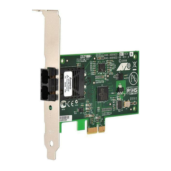
Figure 1. AT-2712FX/SC Adapter Both the AT-2712FX/SC and AT-2712LX20/SC adapters have one SC connector. The AT-2712FX/SC adapter uses a connector that meets 62.5/ 125 µm or 50/125 µm multimode specifications. AT-2712LX20/SC adapter uses a connector that meets 9/125 µm single-mode specifications. -
Page 17: Figure 2. At-2712Fx/Sc Faceplate
See Figure 2 for an illustration of the adapter’s faceplate. Both the AT-2712FX/SC and AT-2712LX20/SC adapters have one fiber port and one LED, as shown in Figure 2 and described in Table 1. 1484 Figure 2. -
Page 18: At-2912T Adapter
Chapter 1: Introducing the Secure Ethernet Network Adapters AT-2912T The AT-2912T adapter is a Gigabit Ethernet secure PCIe NIC featuring on-board encryption. It is fully compatible with other secure IPSec as well Adapter as non-IPSec NICs. This adapter operates at speeds of 10/100/1000T Mbps in both full-duplex and half-duplex modes. -
Page 19: Supported Operating Systems And Features
Microsoft Windows 7 (32-bit and 64-bit extended) Linux (32-bit and 64-bit extended) The following list of features for the AT-2712FX/SC, AT-2712LX20/SC, and AT-2912T adapters applies to all of the supported operating systems: PCI Express x1 interface Flow Control (IEEE 802.1x) ... - Page 20 Chapter 1: Introducing the Secure Ethernet Network Adapters...
-
Page 21: Chapter 2: Installing The Hardware
Chapter 2 Installing the Hardware This chapter provides installation procedures for the adapters. It contains the following sections: “Reviewing Safety Precautions” on page 22 “Reviewing the Contents of Your Shipment” on page 24 “Pre-Installation Checklist” on page 25 ... -
Page 22: Reviewing Safety Precautions
The indicates that a translation of the safety statement is available in a PDF document titled “Translated Safety Statements” on the Allied Telesis website at www.alliedtelesis.com/support/ software. After you have accessed this website, enter the model number in the Search by Product Name box and then click Find to view the current list of documents. - Page 23 Secure Ethernet Network Adapter Installation and User’s Guide - Remove any metallic objects or jewelry from your hands and wrists. - Make sure to use only insulated or nonconducting tools. - Verify that the system is powered OFF and unplugged before accessing internal components.
-
Page 24: Reviewing The Contents Of Your Shipment
See “Returning Products” on page 14. The installation and user guides for all Allied Telesis products are available in PDF format on our web site at www.alliedtelesis.com/ support/software. For further instructions, see “Where to Find... -
Page 25: Pre-Installation Checklist
1. Verify that your system is using the latest BIOS. Note If you acquired the adapter software from the Allied Telesis support website, download the software drivers and then enter the path to where the adapter driver files reside on your system. For instructions that describe how to download the software, see “Where to Find... -
Page 26: Replacing The Bracket
“Replacing the Low-Profile Bracket” on page 26 “Replacing the Standard Bracket” on page 28 In both procedures, the AT-2712FX/SC adapter is shown in the illustrations. However, you can perform the procedures on all three adapters. Replacing the To replace the low-profile bracket with the standard bracket, perform the... -
Page 27: Figure 6. Fastening Screws Onto Standard Bracket
Secure Ethernet Network Adapter Installation and User’s Guide 2. Align the tabs of the standard bracket with the holes on the adapter and fasten the screws onto the adapter. See Figure 6. 1480 Figure 6. Fastening Screws onto Standard Bracket... -
Page 28: Replacing The Standard Bracket
Chapter 2: Installing the Hardware Replacing the To replace the standard bracket with the low-profile bracket, perform the following procedure: Standard Bracket 1. Remove the screws that attach the bracket to the adapter. See Figure 7. 1888 Figure 7. Removing the Standard Bracket 2. -
Page 29: Installing A Network Adapter Card
Secure Ethernet Network Adapter Installation and User’s Guide Installing a Network Adapter Card The following instructions apply to installing the AT-2712FX/SC, AT- 2712LX20/SC, and AT-2912T adapters in most systems. For details about performing these tasks on your particular system, refer to the manuals that were supplied with your system. -
Page 30: Figure 9. Removing The Pc Cover
Chapter 2: Installing the Hardware Figure 9. Removing the PC Cover 3. Select an empty, non-shared PCI slot and remove the faceplate. Keep the faceplate in a safe place. You may need it for future use. See Figure 10. Figure 10. Removing the Faceplate From PCI Slot Note If you cannot locate or do not know how to find an appropriate PCI slot, refer to the documentation that came with your system. -
Page 31: Figure 11. Inserting The Adapter With A High-Profile Bracket
Secure Ethernet Network Adapter Installation and User’s Guide 4. Remove the network adapter card from the shipping package and store the packaging material in a safe location. Caution Wear a grounding device and observe electrostatic discharge precautions when installing the network adapter card in a system. Failure to observe this caution could result in damage to the card. -
Page 32: Figure 12. Securing The Adapter With A High-Profile Bracket
Chapter 2: Installing the Hardware Figure 12. Securing the Adapter with a High-profile Bracket 7. Replace the system’s cover and secure it with the screws removed in Step 2. 8. Disconnect any personal antistatic devices. 9. Power the system on. Once the system returns to proper operation, the adapter hardware is fully installed. -
Page 33: Connecting The Network Cables
Secure Ethernet Network Adapter Installation and User’s Guide Connecting the Network Cables The AT-2712FX/SC and AT-2712LX20/SC adapters have two fiber optic connectors (transmit and receive) for attaching the system to a compatible link partner or an IEEE 802.3z compliant Fast Ethernet switch. Both adapters require a fiber optic cable. - Page 34 17 or “AT-2912T Adapter Physical Description” on page 18. After you connect the system to the network and power is supplied, the AT-2712FX/SC and AT-2712LX20/SC adapters attempt to establish the connection at 100 Mbps full-duplex. The AT-2912T uses...
-
Page 35: Chapter 3: Installing Windows Server 2003 And Windows Xp Driver Software
Chapter 3 Installing Windows Server 2003 and Windows XP Driver Software This chapter describes how to install the Windows Server 2003 and Windows XP driver software. This chapter contains the following sections: “Installing the Driver Software” on page 36 “Uninstalling the Driver Software”... -
Page 36: Installing The Driver Software
If there is an onboard Broadcom network interface, the native Broadcom driver may load. You can use this driver, or the latest driver supplied by Allied Telesis. Using the Driver When you boot up either operating system after installing the adapter card, a series of Found New Hardware windows are displayed. -
Page 37: Figure 13. Welcome To The Found New Hardware Wizard Window
Secure Ethernet Network Adapters Installation and User’s Guide To install the adapter software on a Windows Server 2003 or Windows XP system, do the following: 1. Click Install from a list or specific location (Advanced). Figure 13. Welcome to the Found New Hardware Wizard Window 2. -
Page 38: Figure 14. Found New Hardware Wizard Window: Search And Installation Options
Chapter 3: Installing Windows Server 2003 and Windows XP Driver Software Figure 14. Found New Hardware Wizard Window: Search and Installation Options 3. Click Include this location in the search. 4. Click Browse and locate the path of the software driver. 5. -
Page 39: Updating The Adapter Software
Windows Server 2003 or Windows XP systems. To obtain the latest Adapter Software version of an Secure Ethernet Network adapter software drivers, download it from the Allied Telesis website. For instructions, see “Where to Find Management Software Updates and Product Information” on page 13. Note You may need to reboot your system after completing the driver update to properly load the new drivers. -
Page 40: Figure 15. Windows Server 2003 Start Window
Chapter 3: Installing Windows Server 2003 and Windows XP Driver Software Figure 15. Windows Server 2003 Start Window 3. Select Run from the menu and enter the following command: devmgmt.msc See Figure 16 for an example of the Run Window. Figure 16. -
Page 41: Figure 17. Device Manager Window (Network Adapter Folder Is Collapsed)
The selection expands to show the list of installed network adapter cards. 5. Right click on one of the following the adapters: Allied Telesis AT-2712FX/SC Allied Telesis AT-2912T Note Select “AT-2712FX/SC” to update the drivers for either the AT- 2712FX/SC or the AT-2712LX20/SC adapter. 6. Select Update Driver. -
Page 42: Figure 18. Welcome To Hardware Update Wizard Window
Chapter 3: Installing Windows Server 2003 and Windows XP Driver Software The Hardware Update Wizard Window opens, as shown in Figure 18. Figure 18. Welcome to Hardware Update Wizard Window 7. For a Windows Server 2003 system, skip to step 10. For a Windows XP system, click No, not this time to copy the driver software from your PC. -
Page 43: Modifying Configuration Properties
Secure Ethernet Network Adapters Installation and User’s Guide 9. Click Install from a list or specified location (Advanced). 10. Click Next. 11. If you are prompted to specify the location of the software driver, click Browse (do not use the text field) and locate the path. After you install the driver software, you can modify the configuration properties. -
Page 44: Figure 20. System Properties Dialog Box
Chapter 3: Installing Windows Server 2003 and Windows XP Driver Software Figure 20. System Properties Dialog Box For instructions that describe how to set the Advanced Properties, see Chapter 5, “Setting Advanced Properties” on page 57. -
Page 45: Uninstalling The Driver Software
Before physically removing an adapter from your system, you must uninstall the adapter driver software. Caution Before uninstalling the Allied Telesis device, be sure to capture all Advanced Property settings because the properties are lost during the uninstall process. To uninstall the adapter software from your system, perform the following procedure: 1. - Page 46 Chapter 3: Installing Windows Server 2003 and Windows XP Driver Software 5. Select Uninstall. A Confirm Device Removal window opens. 6. Click OK to complete the uninstall. Note Not all driver files are removed as part of this procedure.
-
Page 47: Chapter 4: Installing The Windows Vista And Windows 7 Driver Software
Chapter 4 Installing the Windows Vista and Windows 7 Driver Software This chapter describes how to install the Windows Vista and Windows 7 driver software on a Secure Ethernet Network adapter. The installation procedures are identical for both the 32-bit and 64-bit Windows Operating systems. -
Page 48: Installing The Driver Software
To install or update the driver software, you must have administrative privileges. To obtain the latest Secure Ethernet Network adapter software drivers, go to the Allied Telesis website at www.alliedtelesis.com/support/ software. For further instructions, see “Where to Find Management Software Updates and Product Information” on page 13. -
Page 49: Figure 21. Windows 7 Search Box
Secure Ethernet Network Adapter Installation and User’s Guide 3. To select the Device Manager in the Windows 7 Operating System, select the Start button. The Windows 7 Search Box is displayed. See Figure 21. Figure 21. Windows 7 Search Box 4. -
Page 50: Figure 22. Windows Vista Start Menu
Chapter 4: Installing the Windows Vista and Windows 7 Driver Software See Figure 22 for an example of the Windows Vista Start menu. Figure 22. Windows Vista Start Menu 6. From the Start Menu, select Run. The Windows Vista Run window is displayed. See Figure 23. Figure 23. -
Page 51: Figure 24. Device Manager Window
The selection expands to show the list of installed network adapter cards installed on your PC. 11. Right click on one of the following adapters: Allied Telesis AT-2712FX/SC Allied Telesis AT-2912T Note Select “AT-2712FX/SC” to update the software drivers on either the AT-2712FX/SC adapter or the AT-2712LX20/SC adapter. -
Page 52: Figure 25. Device Manager Window: Ethernet Controller
Chapter 4: Installing the Windows Vista and Windows 7 Driver Software 12. Right click Ethernet Controller and select Update Driver Software. See Figure 25 for an example of the Device Manger window with Ethernet Controller selected. Figure 25. Device Manager Window: Ethernet Controller 13. -
Page 53: Figure 27. Update Driver Software: Ethernet Controller: Browse
Secure Ethernet Network Adapter Installation and User’s Guide 15. Click Browse to search your computer for the location of the driver software. See Figure 27. Figure 27. Update Driver Software: Ethernet Controller: Browse 16. Click Next. A confirmation message is displayed. See Figure 28. Figure 28. -
Page 54: Uninstalling The Driver Software
You must have Administrator privileges to remove the driver software. Caution Before uninstalling the Allied Telesis device, be sure to capture all of the Advanced Property settings because the properties are lost during the uninstall process. To uninstall the driver software from your system, do the following: 1. - Page 55 Allied Telesis AT-2712FX/SC Allied Telesis AT-2912T Note Select “AT-2712FX/SC” to remove the software drivers on either the AT-2712FX/SC adapter or the AT-2712LX20/SC adapter. The adapter window is displayed. 11. Select Uninstall. A Confirm Device Removal window opens. 12. Click OK to complete the uninstall.
- Page 56 Chapter 4: Installing the Windows Vista and Windows 7 Driver Software...
-
Page 57: Chapter 5: Setting Advanced Properties
Chapter 5 Setting Advanced Properties For all of the Windows operating systems, you access the Windows Advanced Properties from the Advanced Tab. Although the default values of the Advanced Properties are appropriate in most cases, you can change any of the available options to meet the requirements of your system. This chapter discusses the following topics: “Accessing the Advanced Tab”... -
Page 58: Accessing The Advanced Tab
Chapter 5: Setting Advanced Properties Accessing the Advanced Tab To modify the configuration properties of the Windows Operating systems, you must access the Advanced Tab. Depending on your operating system, there are several ways to do this. See the following procedures: “Selecting the Advanced Tab in Windows Server 2003 or Windows ... -
Page 59: Figure 29. System Properties Dialog Box
Secure Ethernet Network Adapters Installation and User’s Guide Figure 29. System Properties Dialog Box 4. Click on the Advanced tab on the System Properties Dialog Box which is located at the top of the window. -
Page 60: Figure 30. Advanced Tab
Chapter 5: Setting Advanced Properties The Advanced tab is shown in Figure 30. Figure 30. Advanced Tab... -
Page 61: Selecting The Advanced Tab In Windows 7
Secure Ethernet Network Adapters Installation and User’s Guide Selecting the To select the Advanced Tab in Windows 7 Operating systems, do the following: Advanced Tab in Windows 7 1. Select the Start button. See Figure 31. Figure 31. Windows 7 Search Box 2. -
Page 62: Figure 32. Device Manager Window
Allied Telesis AT-2712FX/SC Allied Telesis AT-2912T Note Select “AT-2712FX/SC” to indicate either the AT-2712FX/SC adapter or the AT-2712LX20/SC adapter. The adapter window is displayed. 5. Select the Advanced tab. The Advanced tab is shown in Figure 30 on page 60. -
Page 63: Selecting The Advanced Tab In Windows Vista
Secure Ethernet Network Adapters Installation and User’s Guide Selecting the In the Windows Vista Operating System, you access the Advanced Tab through the Device Manager. Advanced Tab in Windows Vista To select the Device Manager in the Windows Vista Operating System, do the following: 1. - Page 64 Allied Telesis AT-2712FX/SC Allied Telesis AT-2912T Note Select “AT-2712FX/SC” to indicate either the AT-2712FX/SC adapter or the AT-2712LX20/SC adapter. The adapter window is displayed. 7. Select the Advanced tab. The Advanced tab is shown in Figure 30 on page 60.
-
Page 65: Modifying Advanced Properties
Secure Ethernet Network Adapters Installation and User’s Guide Modifying Advanced Properties After you have installed the driver software, you can use the following procedures to verify or change the adapter properties: “Updating the Ethernet@ WireSpeed Property” on page 66 “Updating the Flow Control Property”... -
Page 66: Updating The Ethernet@Wirespeed Property
5. If you are prompted to restart your computer, click Yes. Although it is not necessary to reboot the system for new adapter properties to take effect, Allied Telesis recommends rebooting recommended to reinitialize all of the registers. 6. Verify that the adapter port LEDs are operating correctly. See one of the following descriptions: “AT-2712FX/SC and AT-2712LX20/SC Adapters Physical... - Page 67 6. Verify that the port LED operates correctly. See one of the following descriptions: “AT-2712FX/SC and AT-2712LX20/SC Adapters Physical Descriptions” on page 17 “AT-2912T Adapter Physical Description” on page 18...
-
Page 68: Updating The Interrupt Moderation Property
5. If prompted to restart your computer, click Yes. Although it is not necessary to reboot the system for new adapter properties to take effect, Allied Telesis recommends rebooting to reinitialize all of the registers. 6. Verify that the port LED operates correctly. See one of the following descriptions: “AT-2712FX/SC and AT-2712LX20/SC Adapters Physical... -
Page 69: Updating The Checksum Offload Property
6. Verify that the port LED operates correctly. See one of the following descriptions: “AT-2712FX/SC and AT-2712LX20/SC Adapters Physical Descriptions” on page 17 “AT-2912T Adapter Physical Description” on page 18... -
Page 70: Updating The Large Send Offload Property
6. Verify that the port LED operates correctly. See one of the following descriptions: “AT-2712FX/SC and AT-2712LX20/SC Adapters Physical Descriptions” on page 17 “AT-2912T Adapter Physical Description” on page 18... -
Page 71: Updating The Jumbo Mtu Property
6. Verify that the adapter port LEDs are operating correctly. See one of the following descriptions: “AT-2712FX/SC and AT-2712LX20/SC Adapters Physical Descriptions” on page 17 “AT-2912T Adapter Physical Description” on page 18... -
Page 72: Updating The Network Address Property
5. Verify that the port LEDs are operating correctly. See one of the following descriptions: “AT-2712FX/SC and AT-2712LX20/SC Adapters Physical Descriptions” on page 17 “AT-2912T Adapter Physical Description” on page 18... -
Page 73: Updating The Rss Queues Property
6. Verify that the port LED operates correctly. See one of the following descriptions: “AT-2712FX/SC and AT-2712LX20/SC Adapters Physical Descriptions” on page 17 “AT-2912T Adapter Physical Description” on page 18... -
Page 74: Updating The Priority & Vlan Property
6. Verify that the port LEDs are operating correctly. See one of the following descriptions: “AT-2712FX/SC and AT-2712LX20/SC Adapters Physical Descriptions” on page 17 “AT-2912T Adapter Physical Description” on page 18... -
Page 75: Updating The Receive Buffers Property
6. Verify that the port LED operates correctly. See one of the following descriptions: “AT-2712FX/SC and AT-2712LX20/SC Adapters Physical Descriptions” on page 17 “AT-2912T Adapter Physical Description” on page 18 ... -
Page 76: Updating The Speed & Duplex Mode Property
6. Verify that the port LED operates correctly. See one of the following descriptions: “AT-2712FX/SC and AT-2712LX20/SC Adapters Physical Descriptions” on page 17 “AT-2912T Adapter Physical Description” on page 18 ... - Page 77 6. Verify that the port LEDs are operating correctly. See one of the following descriptions: “AT-2712FX/SC and AT-2712LX20/SC Adapters Physical Descriptions” on page 17 “AT-2912T Adapter Physical Description” on page 18...
-
Page 78: Updating The Tcp Connection Offload Properties
6. Verify that the port LED operates correctly. See one of the following descriptions: “AT-2712FX/SC and AT-2712LX20/SC Adapters Physical Descriptions” on page 17 “AT-2912T Adapter Physical Description” on page 18... -
Page 79: Updating The Transmit Buffers Property
6. Verify that the port LED operates correctly. See one of the following descriptions: “AT-2712FX/SC and AT-2712LX20/SC Adapters Physical Descriptions” on page 17 “AT-2912T Adapter Physical Description” on page 18 ... -
Page 80: Updating The Wol Speed
6. Verify that the port LEDs are operating correctly. See one of the following descriptions: “AT-2712FX/SC and AT-2712LX20/SC Adapters Physical Descriptions” on page 17 “AT-2912T Adapter Physical Description” on page 18 ... -
Page 81: Chapter 6: Enabling Linux
Chapter 6 Enabling LINUX This chapter describes how to enable the LINUX System on the AT- 2712FX/SC, AT-2712LX20/SC, and AT-2912T adapters. This chapter contains the following sections: “Introduction” on page 82 “Installing LINUX TG3 File” on page 83 “Unloading and Removing the Driver”... -
Page 82: Introduction
Chapter 6: Enabling LINUX Introduction This chapter describes the tg3 Linux driver for the Broadcom NetXtreme PCI/PCI-X/PCI Express Ethernet Network Controllers. The most recent driver is in the latest 2.6 Linux kernel. You can download the driver from www.broadcom.com as a source package. However, it is generally not necessary to do so if you are using the latest 2.6 upstream kernel from www.kernel.org or one of the latest vendor kernels from Red Hat, SuSE, or other vendors. -
Page 83: Installing Linux Tg3 File
Secure Ethernet Network Adapters Installation and User’s Guide Installing LINUX TG3 File There are two procedures to install the Linux TG3 file: “Installing the Source RPM Package” on page 83 “Building the Driver from the Source TAR File” on page 84 ... -
Page 84: Building The Driver From The Source Tar File
Chapter 6: Enabling LINUX Note The force option may be needed on some Linux distributions if conflicts are reported. Depending on the kernel, the driver is installed in one of the following directories: 2.4.x kernels: /lib/modules/<kernel_version>/kernel/drivers/net/ tg3.o 2.6.x kernels: /lib/modules/<kernel_version>/kernel/drivers/net/ tg3.ko 5. -
Page 85: Driver Settings
Secure Ethernet Network Adapters Installation and User’s Guide 3. The driver is compiled for the running kernel by default. To build the driver for a kernel different from the one running, specify the kernel by defining it in KVER. If this is not necessary, skip to step 4. Enter the following command: make KVER=<kernel_version>... -
Page 86: Driver Default Settings
Chapter 6: Enabling LINUX On Red Hat distributions, you can specify “ethtool -s” parameters in the ifcfg-ethx scripts using the ETHTOOL_OPTS keyword. The specified ethtool parameters are set up during ifup. For example, go to the following directory: /etc/sysconfig/network-scripts/ifcfg-eth0 Add the following line to the script: ETHTOOL_OPTS=”wol g speed 100 duplex half autoneg off”... - Page 87 Secure Ethernet Network Adapters Installation and User’s Guide Table 5. Linux Driver Settings (Continued) Feature Default Setting Rx Ring Size 200 (range 0 - 511) Rx Jumbo Ring Size 100 (range 0 - 255) Tx Ring Size 511 (range (MAX_SKB_FRAGS+1) - 511 Coalesce Rx usecs 20 (range 0 - 1023) Coalesce Rx usecs irq...
-
Page 88: Unloading And Removing The Driver
Chapter 6: Enabling LINUX Unloading and Removing the Driver To unload the driver, use the ifconfig command to bring down all eth# interfaces opened by the driver. Then enter the following command: rmmod tg3 Note On all 2.6 kernels, you do not need to bring down the eth# interfaces before unloading the driver module. -
Page 89: Driver Messages
Secure Ethernet Network Adapters Installation and User’s Guide Driver Messages The following messages are the most common sample messages that are logged in the /var/log/messages file. Use the dmesg -n<level> command to control the level at which messages appear on the console. Most systems are set to level 6 by default. - Page 90 Chapter 6: Enabling LINUX...
-
Page 91: Appendix A: Specifications
Physical Specifications This section provides the dimensions and weight of the adapters. Dimensions: AT-2712FX/SC: 11.59 cm x 6.89 cm (4.56 in. x 2.71 in.) AT-2712LX20/SC: 11.59 cm x 6.89 cm (4.56 in. x 2.71 in.) AT-2912T: 8.18 cm x 6.89 cm (3.22 in. x 2.71 in.) Weight: AT-2712FX/SC: 45.36 g (.10 lbs.) -
Page 92: Power Specifications
3,600,000 hours AT-2712LX20/SC: 800,000 hours AT-2912T: 5,670,000 hours Operating Specifications The following operating specifications apply to the AT-2712FX/SC and AT-2712LX20/SC adapters. AT-2712FX/SC Operating Specifications: Output Optical Power: -9.5 dBm minimum to -4 dBm maximum Input Optical Power: -18 dBm to 0 dBm maximum... -
Page 93: 10/100/1000Base-T Twisted-Pair Port Connectors
Secure Ethernet Network Adapter Installation and User’s Guide Receive Sensitivity: -12.5 dBm with 62.5 um fiber or -13.5 dBm with 50 um fiber AT-2712LX20/SC Operating Specifications: Output Optical Power: -15 dBm minimum to -5 dBm maximum Input Optical Power: -3 dBm maximum Receive Sensitivity: -34 dBm typical 10/100/1000Base-T Twisted-Pair Port Connectors... - Page 94 Appendix A: Specifications Table 7 lists the RJ-45 port pin signals when a twisted-pair port is operating in the MDI-X configuration. Table 7. MDI-X Pin Signals (10Base-T or 100Base-TX) Signal Table 8 lists the RJ-45 connector pin and their signals when a 1000Base-T port is operating at 1000 Mbps.
-
Page 95: Appendix B: Cleaning Fiber Optic Connectors
Appendix B Cleaning Fiber Optic Connectors The fiber optic connector consists of a fiber optic plug and its adapter. The end of the fiber optic cable is held in the core of the ferrule in the plug. Light signals are transmitted through the core of the fiber. Even minor smudges or dirt on the end face of the fiber, completely invisible to the naked eye, can disrupt light transmission and lead to failure of the component or of the entire system. -
Page 96: Using A Cartridge-Type Cleaner
Appendix B: Cleaning Fiber Optic Connectors Using a Cartridge-Type Cleaner Fiber optic cartridge cleaners are available from many vendors and are typically called “cartridge cleaners,” as shown in Figure 38. Figure 38. Cartridge Cleaner Note Do not use compressed air or aerosol air to clean a fiber optic connector. - Page 97 Secure Ethernet Network Adapters Installation and User’s Guide Note Rub the ferrule tip on the cleaning surface in one direction only. 2. Place the ferrule tip on the exposed cleaning surface and rub the ferrule in a downward direction, as shown in Figure 39 on page 96. 3.
-
Page 98: Using A Swab
Appendix B: Cleaning Fiber Optic Connectors Using a Swab Specially treated swabs, known as stick cleaners, are available for cleaning inside connector adapters or hard-to-reach ferrule tips. These swabs, often referred to as “lint free” or “alcohol free” swabs, are available from many vendors, as shown in Figure 40. - Page 99 Secure Ethernet Network Adapters Installation and User’s Guide 3. If a fiber inspection scope is available, use the scope to inspect the connector to make sure that it is clean and to check for scratches, pits, or other problems that may affect performance. Note Always keep a dust cap on a fiber optic cable when it is not in use.
- Page 100 Appendix B: Cleaning Fiber Optic Connectors...
Need help?
Do you have a question about the AT-2712FX and is the answer not in the manual?
Questions and answers