
Subscribe to Our Youtube Channel
Related Manuals for Allied Telesis AT-2911GP/SXLC


Summary of Contents for Allied Telesis AT-2911GP/SXLC
- Page 1 AT-2911GP Network Adapters Gigabit Fiber Ethernet PoE+ Adapters AT-2911GP/SXLC AT-2911GP/SXSC AT-2911GP/LXLC AT-2911GP/LXSC Installation and User’s Guide 613-001872 Rev. A...
- Page 2 Telesis, Inc. be liable for any incidental, special, indirect, or consequential damages whatsoever, including but not limited to lost profits, arising out of or related to this manual or the information contained herein, even if Allied Telesis, Inc. has been...
- Page 3 European Union Restriction of the Use of Certain Hazardous Substances (RoHS) in Electrical and Electronic Equipment This Allied Telesis RoHS-compliant product conforms to the European Union Restriction of the Use of Certain Hazardous Substances (RoHS) in Electrical and Electronic Equipment. Allied Telesis ensures RoHS conformance by requiring supplier Declarations of Conformity, monitoring incoming materials, and maintaining manufacturing process controls.
- Page 4 Translated Safety Statements Important: The indicates that a translation of the safety statement is available in a PDF document titled “Translated Safety Statements” posted on the Allied Telesis website at: www.alliedtelesis.com/support/.
-
Page 5: Table Of Contents
Contents Preface ....................................9 Safety Symbols Used in this Document..........................10 Contacting Allied Telesis ..............................11 Chapter 1: Introduction ..............................13 Description....................................14 AT-2911GP Models ...............................14 PoE+ Capable ................................14 Dual Port Adapter ................................15 Bridge to Connect Two Ports to One Network.......................15 SC Fiber Optic Adapter ..............................16 LC Fiber Optic Adapter..............................16... - Page 6 AT-2911GP Gigabit Fiber Ethernet PoE+ Adapters Installation and User’s Guide Performing the Silent Installation ............................60 Installing the Driver Silently ............................60 Viewing Supported DPInst Options ..........................61 Chapter 4: Installing the AT-MUX Utility ..........................63 Overview ....................................64 Supported Operating Systems ............................64 Guidelines..................................64 Using the AT-MUX Utility ...............................64 Downloading the AT-MUX Utility Setup File .........................65 Installing the AT-MUX Utility ..............................67 Accessing the AT-MUX Utility ...............................69...
- Page 7 Contents VMQ VLAN Filtering ................................127 Wake Up Capabilities .................................128 Wake on Magic Packet ...............................130 Wake on Pattern Match ..............................131 WOL Speed ..................................132 Chapter 7: Uninstalling the Driver Software .........................133 Overview.....................................134 Guidelines ...................................134 Uninstalling the Driver Software Using Device Manager ....................135 Uninstalling the Driver Software Silently..........................137 Chapter 8: Troubleshooting ............................139 Checking the Port LED on the Adapter ..........................140...
- Page 8 AT-2911GP Gigabit Fiber Ethernet PoE+ Adapters Installation and User’s Guide...
-
Page 9: Preface
Fiber Ethernet PoE+ Adapter cards. The adapter cards included in this series are: AT-2911GP/SXLC AT-2911GP/SXSC AT-2911GP/LXLC AT-2911GP/LXSC The Preface contains the following sections: “Safety Symbols Used in this Document” on page 10 “Contacting Allied Telesis” on page 11 ... -
Page 10: Safety Symbols Used In This Document
AT-2911GP Gigabit Fiber Ethernet PoE+ Adapters Installation and User’s Guide Safety Symbols Used in this Document This document uses the following conventions: Note Notes provide additional information. Caution Cautions inform you that performing or omitting a specific action may result in equipment damage or loss of data. Warning Warnings inform you that performing or omitting a specific action may result in bodily injury. -
Page 11: Contacting Allied Telesis
Preface Contacting Allied Telesis If you need assistance with this product, you may contact Allied Telesis technical support by going to the Support & Services section of the Allied Telesis web site at www.alliedtelesis.com/support. You can find links for the following services on this page: 24/7 Online Support - Enter our interactive support ... - Page 12 AT-2911GP Gigabit Fiber Ethernet PoE+ Adapters Installation and User’s Guide...
-
Page 13: Chapter 1: Introduction
Chapter 1 Introduction This chapter provides an introduction to the Allied Telesis AT-2911GP Gigabit Fiber Ethernet PoE+ Adapter cards. This chapter contains the following sections: “Description” on page 14 “Model Naming Conventions” on page 18 “Supported Operating Systems” on page 19 ... -
Page 14: Description
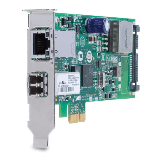
PC to two separate networks. As a bridge, the adapter connects two ports on the card to the same network. Figure 1 shows the AT-2911GP/LXSC model. Figure 1. AT-2911GP Adapter Card AT-2911GP The AT-2911GP series offers the following models: Models AT-2911GP/SXLC AT-2911GP/SXSC AT-2911GP/LXLC AT-2911GP/LXSC ... -
Page 15: Dual Port Adapter
Chapter 1: Introduction Dual Port The AT-2911GP adapter is a dual port adapter to connect a PC to two separate networks. You can assign an IP address to each port. Adapter After you physically install the AT-2911GP adapter on your Windows operating system, you must install driver software. -
Page 16: Sc Fiber Optic Adapter
To connect the SC adapter to a network cable, you must have a fiber optic network cable with the SC connector. LC Fiber Optic The AT-2911GP/SXLC and AT-2911GP/LXLC adapter cards are equipped with a 1000BASE-SX or 1000BASE-LX port with the LC adapter. Adapter The LC fiber optic adapter is shown in Figure 4. -
Page 17: Led
Chapter 1: Introduction The AT-2911GP adapter card comes with two LED’s built into the copper port as shown in Figure 7. The LED away from the fiber optic port indicates the link and activity status of the copper port; the LED close to the fiber optic port indicates the link and activity status of the fiber optic port. -
Page 18: Model Naming Conventions
AT-2911GP Gigabit Fiber Ethernet PoE+ Adapters Installation and User’s Guide Model Naming Conventions The hardware features of the AT-2911GP adapter cards are represented by the letters and numbers in the model names. The conventions for the AT-2911GP adapter cards are identified in Figure 8. Figure 8. -
Page 19: Supported Operating Systems
Chapter 1: Introduction Supported Operating Systems The AT-2911GP adapter card can be used as a dual port adapter or a bridge to connect two ports. Dual Port The following list shows the supported operating systems to use the AT- 2911GP adapter card as a dual port adapter: Adapter Windows 8 ... -
Page 20: Accessing Documents
AT-2911GP Gigabit Fiber Ethernet PoE+ Adapters Installation and User’s Guide Accessing Documents Documents for AT-2911GP adapter cards are available at Allied Telesis websites. Allied Telesis To access documents for AT-2911GP adapter cards, do the following: Documents 1. Open a web browser, such as Internet Explorer or FireFox, on your system and enter the following: http://www.alliedtelesis.com/... -
Page 21: Contents Of Your Shipment
The AT-2911GP adapter card is not shipped with a software driver CD. You must download the driver software for Windows from the Allied Telesis website. See Chapter 3, “Downloading the Driver Software” on page 37. Inform your network equipment supplier of any missing or damaged items. -
Page 22: Warranty Registration
Warranty Registration Allied Telesis hardware products are covered under limited warranties. All Allied Telesis warranties are subject to and provided only on the terms and conditions set out in the Allied Telesis Limited Warranties listed on the Allied Telesis website at http://alliedtelesis.com/support/warranty. -
Page 23: Chapter 2: Installing The Hardware
Chapter 2 Installing the Hardware This chapter contains the following sections: “System Requirements” on page 24 “Reviewing Safety Precautions” on page 25 “Pre-Installation Checklist” on page 27 “Replacing the Bracket” on page 28 “Installing a Network Adapter Card” on page 30 ... -
Page 24: System Requirements
AT-2911GP Gigabit Fiber Ethernet PoE+ Adapters Installation and User’s Guide System Requirements Before installing the AT-2911GP adapter card, make sure your system meets the requirements listed below: PC with one of the following operating systems installed: – Windows 8 –... -
Page 25: Reviewing Safety Precautions
Note indicates that a translation of the safety statement is available in a PDF document titled “Translated Safety Statements” posted on the Allied Telesis website at www.alliedtelesis.com/ support/software/. Warning Do not stare into the laser beam. ... - Page 26 AT-2911GP Gigabit Fiber Ethernet PoE+ Adapters Installation and User’s Guide Warning The module is being installed in a system that operates with voltages that can be lethal. Before you remove the cover of your system, you must observe the following precautions to protect yourself and to prevent damage to the system components.
-
Page 27: Pre-Installation Checklist
2. Check that the power supply on your computer has a SATA power connector. 3. Verify that your system is using the latest BIOS. 4. When you download the driver software from the Allied Telesis website, record the path to where the driver file resides on your system. -
Page 28: Replacing The Bracket
AT-2911GP Gigabit Fiber Ethernet PoE+ Adapters Installation and User’s Guide Replacing the Bracket The AT-2911GP adapter card is shipped with the low-profile bracket attached to the adapter. Depending on your system, you may need to replace the bracket attached to your adapter card. The following procedure describes how to remove the low-profile bracket from the adapter card and replace it with the standard bracket. - Page 29 Chapter 2: Installing the Hardware Figure 10. Fastening Screws onto Standard Bracket...
-
Page 30: Installing A Network Adapter Card
AT-2911GP Gigabit Fiber Ethernet PoE+ Adapters Installation and User’s Guide Installing a Network Adapter Card The following instructions apply to installing an AT-2911GP adapter card in most systems. Refer to the manuals that were supplied with your system for details about performing these tasks on your particular system. To install the network adapter card, perform the following procedure: 1. - Page 31 Chapter 2: Installing the Hardware 3. Select an empty, non-shared PCIe slot and remove the faceplate. Keep the faceplate in a safe place. You may need it for future use. See Figure 12. Figure 12. Removing the Faceplate From PCIe Slot Note If you cannot locate or know how to find a PCIe slot, refer to the documentation that came with your system.
- Page 32 AT-2911GP Gigabit Fiber Ethernet PoE+ Adapters Installation and User’s Guide Figure 13. Inserting the Network Adapter Card Caution Do not use excessive force when seating the card, as the force may damage the system or the adapter card. If the card resists seating, remove it from the system, realign it, and try again.
- Page 33 Chapter 2: Installing the Hardware Figure 15. Connecting the SATA Receptacle 8. Replace the system’s cover and secure it with the screws removed in step 2. 9. Disconnect any personal antistatic devices. 10. Power the system on. Note If you installed the adapter card in Windows XP system before installing the driver software, the Found New Hardware Wizard launches automatically.
-
Page 34: Connecting The Network Cables
AT-2911GP Gigabit Fiber Ethernet PoE+ Adapters Installation and User’s Guide Connecting the Network Cables The AT-2911GP adapter card is equipped with the fiber optic and PoE+ copper ports. The fiber optic port is for the network; the PoE+ copper port is for a PoE Powered Device (PD), such as a VoIP phone. -
Page 35: Chapter 3: Installing The Driver Software
Chapter 3 Installing the Driver Software This chapter describes how to install driver software for the AT-2911GP adapter card onto your operating system. It contains the following topics: “Overview” on page 36 “Downloading the Driver Software” on page 37 ... -
Page 36: Overview
AT-2911GP Gigabit Fiber Ethernet PoE+ Adapters Installation and User’s Guide Overview When you install the AT-2911GP adapter card on your computer, your next step is to install driver software onto your Windows operating system. You can install driver software using Device Manager or using the silent installation method. -
Page 37: Downloading The Driver Software
Downloading the Driver Software The AT-2911GP adapter is not shipped with a software driver CD. You must download driver software from the Allied Telesis website. To download driver software, do the following: 1. Open a web browser, such as Internet Explorer or FireFox, on your system and enter the following: http://www.alliedtelesis.com/support/software... - Page 38 AT-2911GP Gigabit Fiber Ethernet PoE+ Adapters Installation and User’s Guide 5. Save the zip folder onto your system. 6. Right-click the zip folder and select Extract All. A window as shown in Figure 17 pops up and prompts you to specify the location of a folder that you want to place unzipped files in.
-
Page 39: Accessing The Device Manager
Chapter 3: Installing the Driver Software Accessing the Device Manager When you install or update the driver software for AT-2911GP adapter card, you must first access Device Manager. The procedures for accessing Device Manager are slightly different among Windows operating systems. To access Device Manager on your operating system, follow one of the procedures below: “Accessing Device Manager on Windows Server 2012 or Windows 8,”... - Page 40 Controller entries as shown in Figure 20 on page 41. Note The Windows system lists two entries as Ethernet Controllers if no driver is installed. The system may list entries as Broadcom NetXtreme devices or Allied Telesis devices. For more information, see “Guidelines” on page 36.
-
Page 41: Accessing Device Manager On Windows Server 2008, Windows Vista, Or Windows 7
Chapter 3: Installing the Driver Software Figure 20. Device Manager on Windows Server 2012 and Windows 8 Accessing Device To access Device Manager on Windows Server 2008, Windows Vista, or Windows 7, do the following: Manager on Windows Server 1. Right-click the Computer icon on the desktop and select Properties. 2008, Windows The System window is opened as shown in Figure 21. -
Page 42: Accessing Device Manager On Windows Server 2003 Or Windows Xp
The Windows system lists two entries as Ethernet Controllers if no driver is installed. The system may list entries as Broadcom NetXtreme devices or Allied Telesis devices. For more information, see “Guidelines” on page 36. Figure 22. Device Manager Window on Server 2008, Vista, and 7... - Page 43 Chapter 3: Installing the Driver Software Figure 23. System Properties Window on Windows Server 2003 and XP 2. Select the Hardware Tab. The Hardware page is shown in Figure 24. Figure 24. Hardware Page on Windows Server 2003 and XP 3.
- Page 44 The Windows system lists two entries as Ethernet Controllers if no driver is installed. The system may list entries as Broadcom NetXtreme devices or Allied Telesis devices. For more information, see “Guidelines” on page 36. Figure 25. Device Manager Window on Windows Server 2003 and XP...
-
Page 45: Installing The Driver Software
The Windows system lists two entries as Ethernet Controllers if no driver is installed. The system may list entries as Broadcom NetXtreme devices or Allied Telesis devices. For more information, see “Guidelines” on page 36. The shortcut menu appears as shown in Figure 26 on page 46. - Page 46 AT-2911GP Gigabit Fiber Ethernet PoE+ Adapters Installation and User’s Guide Figure 26. Ethernet Controller on Windows Server 2012 and Windows 8 3. Select Update Driver Software. The Update Driver Software window pops up as shown in Figure 27. Figure 27. Update Driver Software Window on Windows Server 2012 and Windows 8...
- Page 47 Chapter 3: Installing the Driver Software 4. Select Browse my computer for driver software. The Update Driver Software window prompts you to enter the location of the driver folder as shown in Figure 28. Figure 28. Update Driver Software Window on Windows Server 2012 and Windows 8 5.
-
Page 48: Installing The Driver Software On Windows Server 2008, Windows Vista, Or Windows 7
The Windows system lists two entries as Ethernet Controllers if no driver is installed. The system may list entries as Broadcom NetXtreme devices or Allied Telesis devices. For more information, see “Guidelines” on page 36. The shortcut menu appears as shown in Figure 30 on page 49. - Page 49 Chapter 3: Installing the Driver Software Figure 30. Ethernet Controller on Windows Server 2008, Vista, and 7 3. Select Update Driver Software. The Update Driver Software window pops up as shown in Figure 31. Figure 31. Update Driver Software Window on Windows Server 2008, Vista, and 7...
- Page 50 AT-2911GP Gigabit Fiber Ethernet PoE+ Adapters Installation and User’s Guide 4. Select Browse my computer for driver software. The Update Driver Software window prompts you to enter the location of the driver folder as shown in Figure 32. Figure 32. Update Driver Software on Windows Server 2008, Vista, and 7 5.
-
Page 51: Installing The Driver Software On Windows Server 2003 Or Windows Xp
The Windows system lists two entries as Ethernet Controllers if no driver is installed. The system may list entries as Broadcom NetXtreme devices or Allied Telesis devices. For more information, see “Guidelines” on page 36. The shortcut menu appears as shown in Figure 34 on page 51. - Page 52 AT-2911GP Gigabit Fiber Ethernet PoE+ Adapters Installation and User’s Guide Figure 35. Hardware Update Wizard 1 4. Select No, not this time. 5. Click Next. The Hardware Update Wizard prompts you to select one of two options as shown in Figure 36 Figure 36.
- Page 53 Chapter 3: Installing the Driver Software 6. Select Install from a list or specific location (Advanced). 7. Click Next. The Hardware Update Wizard prompts you to specify the location of your driver software as shown in Figure 37 on page 53. Figure 37.
- Page 54 AT-2911GP Gigabit Fiber Ethernet PoE+ Adapters Installation and User’s Guide Figure 38. Hardware Update Wizard 4 10. Click Finish. 11. Repeat step 2 to step 10 on the other Ethernet Controller entry.
-
Page 55: Updating The Driver Software
If your operating system automatically installs a default driver or Broadcom driver, you need to update the driver software with the driver that you downloaded from the Allied Telesis website. To obtain the latest version of the AT-2911GP adapter driver, see “Downloading the Driver Software” on page 37. - Page 56 5. Specify the location of the driver software. 6. Click Next. The confirmation message appears when the driver software is successfully updated. See Figure 29 on page 48. 7. Click Close. 8. Repeat step 2 to step 7 on the other Allied Telesis AT-2911GP Ethernet entry.
-
Page 57: Updating The Driver On Windows Server 2008, Windows Vista, Or Windows 7
1. Access the Device Manager. See “Accessing Device Manager on 2008, Windows Windows Server 2008, Windows Vista, or Windows 7” on page 41. Vista, or 2. In the Device Manager window, right-click an Allied Telesis Windows 7 AT-2911GP Ethernet entry. The shortcut menu appears as shown in Figure 40. -
Page 58: Updating The Driver On Windows Server 2003 Or Windows Xp
AT-2911GP Gigabit Fiber Ethernet PoE+ Adapters Installation and User’s Guide 8. Repeat step 2 to step 7 on the other Allied Telesis AT-2911GP Ethernet entry. Updating the To install the driver software for the AT-2911GP adapter card onto the Windows Server 2003 and Windows XP, do the following:... - Page 59 8. Specify the location of the driver software that you downloaded from Allied Telesis website. 9. Click Next. The confirmation message is displayed as shown in Figure 38 on page 10. Click Finish. 11. Repeat step 2 to step 10 on the other Allied Telesis AT-2911GP Ethernet entry.
-
Page 60: Performing The Silent Installation
Note You can apply the silent installation method only to Microsoft certified drivers. The drivers that Allied Telesis provides for the AT- 2911GP adapters are all Microsoft certified. Use a command line utility called Driver package Installer (DPInst) for the silent installation. -
Page 61: Viewing Supported Dpinst Options
Chapter 3: Installing the Driver Software 7. Change the directory to the folder where the dpinst utility and the driver files reside. 8. Install the driver in the silent mode by entering the following command: > dpinst /S Note Adding the /S switch to the dpinst command suppresses the display of wizard pages, user dialog boxes, and other user intervention requests. - Page 62 AT-2911GP Gigabit Fiber Ethernet PoE+ Adapters Installation and User’s Guide...
-
Page 63: Chapter 4: Installing The At-Mux Utility
Chapter 4 Installing the AT-MUX Utility This chapter describes how to install the AT-MUX utility onto your operating system and set VLAN properties. This chapter contains the following topics: “Overview” on page 64 “Downloading the AT-MUX Utility Setup File” on page 65 ... -
Page 64: Overview
AT-2911GP Gigabit Fiber Ethernet PoE+ Adapters Installation and User’s Guide Overview The AT-MUX utility is a Windows based application that bridges the fiber optic port to the copper port. Once you installed the AT-MUX utility on your system, the copper port of the AT-2911GP adapter card turns into a switch port. -
Page 65: Downloading The At-Mux Utility Setup File
Chapter 4: Installing the AT-MUX Utility Downloading the AT-MUX Utility Setup File The AT-2911GP adapter is not shipped with a AT-MUX utility CD. You must download the AT-MUX utility setup file from the Allied Telesis website. To download driver software, do the following: 1. - Page 66 AT-2911GP Gigabit Fiber Ethernet PoE+ Adapters Installation and User’s Guide 5. Save the zip folder onto your system. 6. Right-click the zip folder and select Extract All. A window as shown in Figure 43 pops up and prompts you to specify the location of a folder that you want to place unzipped files in.
-
Page 67: Installing The At-Mux Utility
Chapter 4: Installing the AT-MUX Utility Installing the AT-MUX Utility After you download the AT-MUX utility setup file from Allied Telesis website, install the AT-MUX utility. Note To install the AT-MUX utility, you must have administrative privileges. 1. Click the AT-MUX utility setup file that you just downloaded. - Page 68 AT-2911GP Gigabit Fiber Ethernet PoE+ Adapters Installation and User’s Guide Figure 45. AT-MUX Setup Wizard 2 3. Click Next. The confirmation message appears as shown in Figure 46 when the AT-MUX utility is successfully installed. Figure 46. Figure 46. AT-MUX Setup Wizard 3 4.
-
Page 69: Accessing The At-Mux Utility
Chapter 4: Installing the AT-MUX Utility Accessing the AT-MUX Utility To configure the AT-MUX utility, do the following: Note The procedures for accessing the AT-MUX utility are slightly different among Windows operating systems. The following instructions is for Windows 7 operating system to show an example. 1. - Page 70 AT-2911GP Gigabit Fiber Ethernet PoE+ Adapters Installation and User’s Guide Figure 48. Network and Internet in Control Panel 4. Click ATI Vlan Setup. The AT-MUX utility starts as shown in Figure 49. Figure 49. AT-MUX Utility 5. Click one of the ATI Virtual LAN Adapter entries. The Vlan Settings windows pops up as shown in Figure 50 on page...
- Page 71 Chapter 4: Installing the AT-MUX Utility Figure 50. AT-MUX Vlan Settings 6. Specify the Vlan ID and Priority. Vlan ID— The range is from 0 to 4055. Priority — The range is from 0 to 7. 7. Click OK. 8.
-
Page 72: Uninstalling The At-Mux Utility
AT-2911GP Gigabit Fiber Ethernet PoE+ Adapters Installation and User’s Guide Uninstalling the AT-MUX Utility If you want to use the copper port on the AT-2911GP adapter as a regular network port, you must uninstall the AT-MUX utility. To uninstall the AT-MUX utility from your operating system, do the following: Note The procedures for uninstalling a program are slightly different... - Page 73 Chapter 4: Installing the AT-MUX Utility Figure 52. Control Panel - Programs and Features 4. Double-click Allied Telesis ATMux Ethernet Bridge Driver. A confirmation window pops up as shown in Figure 53. Figure 53. Uninstall Confirmation Window 5. Click Yes.
- Page 74 AT-2911GP Gigabit Fiber Ethernet PoE+ Adapters Installation and User’s Guide...
-
Page 75: Chapter 5: Configuring A Voip Phone System
Chapter 5 Configuring a VoIP Phone System This chapter describes how to configure a VoIP phone system using AT- 2911GP adapters. It contains the following topics: “Overview” on page 76 “Configuring VLAN Tagging on Adapter Ports” on page 77 ... -
Page 76: Overview
AT-2911GP Gigabit Fiber Ethernet PoE+ Adapters Installation and User’s Guide Overview The AT-2911GP adapter card is installed on a PC and connects the PC to the Ethernet network through the fiber optic port and a Powered Device (PD) through the PoE+ copper port. A PD is a device powered through an Ethernet cable by a Power Supply Equipment (PSE). -
Page 77: Configuring Vlan Tagging On Adapter Ports
Chapter 5: Configuring a VoIP Phone System Configuring VLAN Tagging on Adapter Ports To separate voice traffic coming from the VoIP phone from data traffic from the PC, several combinations of VLAN tagging settings are possible. VLAN Tagging Figure 55 illustrates possible VLAN tagging combinations. In this example, voice frames belong to the VLAN 150 and data frames belong to the VLAN Combinations Figure 55. -
Page 78: Using Vlan-Capable Voip Phones
AT-2911GP Gigabit Fiber Ethernet PoE+ Adapters Installation and User’s Guide Using VLAN- Some VoIP phones are capable of VLAN tagging. Config 1 and Config 2 are using VLAN-capable VoIP phones. If your VoIP phone is VLAN Capable VoIP capable, assigns the VLAN ID 150 to a VoIP phone setting. Voice frames Phones get the VLAN tagged at the phone, are sent to the copper port, and transmitted to the switch through the fiber port. -
Page 79: Chapter 6: Modifying Advanced Properties
Chapter 6 Modifying Advanced Properties This chapter includes the following topics: “Overview” on page 81 “Supported Advanced Properties” on page 82 “Accessing Advanced Properties” on page 87 “802.1p QOS” on page 89 “802.3az EEE” on page 90 ... - Page 80 AT-2911GP Gigabit Fiber Ethernet PoE+ Adapters Installation and User’s Guide “Virtual Machine Queues” on page 125 “VLAN ID” on page 126 “VMQ VLAN Filtering” on page 127 “Wake Up Capabilities” on page 128 “Wake on Magic Packet” on page 130 ...
-
Page 81: Overview
Chapter 6: Modifying Advanced Properties Overview The AT-2911GP adapter ports allow you to modify advanced properties to meet your requirements. To access the advanced properties, access Device Manager, then go to each advanced property page. Guidelines Here are the guidelines to modifying the advanced properties: To change the advanced property settings, you must have ... -
Page 82: Supported Advanced Properties
AT-2911GP Gigabit Fiber Ethernet PoE+ Adapters Installation and User’s Guide Supported Advanced Properties The supported advanced properties depend upon the driver version, interface, and the operating system that the adapter is installed on. Windows XP and Table 4 shows lists of supported advanced properties for fiber and copper interfaces when the adapter is installed on Windows XP or Windows Server 2003 Server 2003. - Page 83 Chapter 6: Modifying Advanced Properties Table 5. Advanced Properties for Windows Vista and Server 2008 Windows Vista and Server 2008 Advanced Property v. 15.2.0.5 v. 15.6.0.3 Fiber Copper Fiber Copper “802.3az EEE” on page 90 “EEE Control Policies” on page 94 “Ethernet@WireSpeed”...
-
Page 84: Windows 7 And Server 2008 R2
AT-2911GP Gigabit Fiber Ethernet PoE+ Adapters Installation and User’s Guide Windows 7 and Table 6 shows lists of supported advanced properties when the adapter is installed on Windows 7 or Windows Server 2008 R2. Driver software Server 2008 R2 versions 15.2.0.5 and 15.6.0.3 are available for Windows 7 and Windows Server 2008 R2. -
Page 85: Windows 8 And Server 2012
Chapter 6: Modifying Advanced Properties Table 6. Advanced Properties for Windows 7 and Server 2008 R2 (Continued) Windows 7 and Server 2012 Advanced Property v. 15.2.0.5 v. 15.6.0.3 Fiber Copper Fiber Copper “TCP/UDP Checksum Offload (IPv4)” on page 120 “TCP/UDP Checksum Offload (IPv6)” on page 122 “Transmit Buffers”... - Page 86 AT-2911GP Gigabit Fiber Ethernet PoE+ Adapters Installation and User’s Guide Table 7. Advanced Properties for Windows Server 2008 R2 (Continued) Windows 8 and Server 2012 Advanced Property v. 15.6.0.3 Fiber Copper “Ethernet@WireSpeed” on page 96 “Flow Control” on page 97 “Interrupt Moderation”...
-
Page 87: Accessing Advanced Properties
“Accessing Device Manager on Windows Server 2012 or Windows 8” on page 39 2. In the Device Manager window, double-click Allied Telesis AT- 2911GP Gigabit Fiber Ethernet or Allied Telesis AT-2911GP Gigabit Copper Ethernet. The properties window pops up as shown in Figure 56. - Page 88 AT-2911GP Gigabit Fiber Ethernet PoE+ Adapters Installation and User’s Guide 3. Click the Advanced tab. The Advanced Properties window opens as shown in Figure 57. Figure 57. Advanced Properties Window...
-
Page 89: Qos
Chapter 6: Modifying Advanced Properties 802.1p QOS The 802.1p QOS property allows you to enable or disable the Quality of Service (QoS) feature on the adapter. QoS is a network standard for managing traffic by assigning priority to packets. Note Enable the 802.1p QOS property only when the network supports QoS. -
Page 90: Az Eee
AT-2911GP Gigabit Fiber Ethernet PoE+ Adapters Installation and User’s Guide 802.3az EEE The 802.3az EEE (Energy Efficient Ethernet) property allows you to optimize the energy usage of a copper interface over Ethernet. To enable or disable the 802.3az EEE feature, do the following: 1. -
Page 91: Arp Offload
Chapter 6: Modifying Advanced Properties ARP Offload The ARP Offload feature enables the adapter not to wake up when responding to an ARP request. ARP is used to verify whether a computer is still present on the network and resolute an IP address into a MAC address. -
Page 92: Checksum Offload
AT-2911GP Gigabit Fiber Ethernet PoE+ Adapters Installation and User’s Guide Checksum Offload The Checksum Offload feature allows the adapter to verify the TCP/IP checksum to enhance receive and transmit performance and reduce CPU utilization. To enable or disable the Checksum Offload feature, do the following: 1. - Page 93 Chapter 6: Modifying Advanced Properties 3. Select one of the following options: None — The TCP/IP checksum feature is disabled. Rx TCP/IP Checksum — The adapter verifies TCP/IP checksum only for receiving packets. Tx TCP/IP Checksum — The adapter verifies TCP/IP checksum ...
-
Page 94: Eee Control Policies
AT-2911GP Gigabit Fiber Ethernet PoE+ Adapters Installation and User’s Guide EEE Control Policies The EEE (Energy-Efficient Ethernet) Control Policies feature enables the adapter to manage power for the best performance. To change the setting of the EEE Control Policies feature, do the following: 1. - Page 95 Chapter 6: Modifying Advanced Properties Maximum Power Saving — The adapter manages power for the best energy saving. 4. Click OK.
-
Page 96: Ethernet@Wirespeed
AT-2911GP Gigabit Fiber Ethernet PoE+ Adapters Installation and User’s Guide Ethernet@WireSpeed The Ethernet@WireSpeed feature connects two gigabit devices even when the devices are connected through an impaired copper cable. To view the Ethernet@WireSpeed setting, do the following: 1. Access the Advanced Properties. See “Accessing Advanced Properties”... -
Page 97: Flow Control
Chapter 6: Modifying Advanced Properties Flow Control The Flow Control feature allows you to control the flow between the AT-2911GP adapter port and its link partner. You can enable or disable the adapter port to process received PAUSE frames and transmit PAUSE frames. - Page 98 AT-2911GP Gigabit Fiber Ethernet PoE+ Adapters Installation and User’s Guide Tx & Rx Enabled (Tx/Rx PAUSE) — The adapter processes PAUSE frames when receiving and transmits PAUSE frames. Rx Enabled (Rx PAUSE) — The adapter processes PAUSE frames when receiving, but does not transmit PAUSE frame. Tx Enabled (Tx PAUSE) —...
-
Page 99: Interrupt Moderation
Chapter 6: Modifying Advanced Properties Interrupt Moderation The Interrupt Moderation feature allows you to limit the rate of interrupts to the CPU during packet transmission and packet reception. When this feature is enabled, interrupts are handled as a group so that the CPU utilization decreases;... -
Page 100: Ipv4 Checksum Offload
AT-2911GP Gigabit Fiber Ethernet PoE+ Adapters Installation and User’s Guide IPv4 Checksum Offload The IPv4 Checksum Offload feature allows the adapter to verify the IPv4 checksum to enhance IPv4 receive and transmit performance and reduce CPU utilization. To enable or disable the IPv4 Checksum Offload feature, do the following: 1. -
Page 101: Jumbo Mtu
Chapter 6: Modifying Advanced Properties Jumbo Mtu The Jumbo Mtu (Maximum transmission unit) feature allows you to specify the size of the Ethernet frame that the adapter port supports. The network performance usually improves when the larger frame size is specified; however, the network must be capable of supporting the oversized Ethernet frames. -
Page 102: Large Send Offload
AT-2911GP Gigabit Fiber Ethernet PoE+ Adapters Installation and User’s Guide Large Send Offload The Large Send Offload feature allows you to control the load of sending out large packets. When this feature is enabled, the adapter segments large packets and reduces the CPU load. To enable or disable the Large Send Offload feature, do the following: 1. -
Page 103: Large Send Offload (Ipv4)
Chapter 6: Modifying Advanced Properties Large Send Offload (IPv4) The Large Send Offload (IPv4) feature allows you to control the load of sending out large packets. When this feature is enabled, the adapter port segments large packets and reduces the CPU load. The Large Send Offload (IPv4) feature supports large packets up to 64kb. - Page 104 AT-2911GP Gigabit Fiber Ethernet PoE+ Adapters Installation and User’s Guide 3. Select one of the following options: Disable — This feature is disabled. Enable — The adapter port segments large packets up to 64kb for IPv4 traffic before sending them out. This is the default setting. 4.
-
Page 105: Large Send Offload V2 (Ipv4)
Chapter 6: Modifying Advanced Properties Large Send Offload v2 (IPv4) The Large Send Offload v2 (IPv4) feature allows you to control the load of sending out large packets. When this feature is enabled, the adapter port segments large packets for IPv4 traffic and reduces the CPU load. This feature, which supports large packets up to 256kb, overrides the Large Send Offload (IPv4) feature if both features are enabled. - Page 106 AT-2911GP Gigabit Fiber Ethernet PoE+ Adapters Installation and User’s Guide 3. Select one of the following options: Disable — The feature is disabled. Enable — The adapter port segments large packets up to 256kb for IPv4 traffic before sending them out. This is the default setting. 4.
-
Page 107: Large Send Offload V2 (Ipv6)
Chapter 6: Modifying Advanced Properties Large Send Offload v2 (IPv6) The Large Send Offload v2 (IPv6) feature allows you to control the load of sending out large packets. When this feature is enabled, the adapter port segments large packets for IPv6 traffic and reduces the CPU load. To enable or disable the Large Send Offload v2 (IPv6) feature, do the following: 1. -
Page 108: Locally Administered Address
AT-2911GP Gigabit Fiber Ethernet PoE+ Adapters Installation and User’s Guide Locally Administered Address The Locally Administered Address allows you to replace the MAC address originally assigned to the adapter with a user-defined address. The user- defined address that you assign to the adapter is called a locally administered address. - Page 109 Chapter 6: Modifying Advanced Properties Figure 72. Locally Administered Address Page 3. In the Value text box, enter a locally administered address for the AT-2911GP adapter. By default, no locally administered address is assigned. 4. Click OK.
-
Page 110: Network Address
AT-2911GP Gigabit Fiber Ethernet PoE+ Adapters Installation and User’s Guide Network Address The Network Address property allows you to replace the MAC address originally assigned to the adapter with a user-defined address. The user- defined address that you assign to the adapter is called a locally administered address. - Page 111 Chapter 6: Modifying Advanced Properties 3. In the Value text box, enter a locally administered address for the AT-2911GP adapter. By default, no locally administered address is assigned. For more information, see “Guidelines for Assigning a Locally Administered Address” on page 108. 4.
-
Page 112: Ns Offload
AT-2911GP Gigabit Fiber Ethernet PoE+ Adapters Installation and User’s Guide NS Offload The NS (Neighbor Solicitation) Offload feature enables the adapter not to wake up when responding to an NS request. To enable or disable the NS Offload feature, do the following: 1. -
Page 113: Priority & Vlan
Chapter 6: Modifying Advanced Properties Priority & VLAN The Priority & VLAN feature allows you to control sending and receiving tagged frames of QoS and VLAN. Note When you install the AT-MUX utility on your system to bridge frames from the copper port to the fiber port, set a priority and VLAN ID in the AT-MUX utility. - Page 114 AT-2911GP Gigabit Fiber Ethernet PoE+ Adapters Installation and User’s Guide 3. Select one of the following options: Priority & VLAN Enabled — The adapter sends and receives QoS and VLAN tagged frames. This is the default setting. Priority & VLAN Disabled — The adapter does not send and ...
-
Page 115: Receive Buffers
Chapter 6: Modifying Advanced Properties Receive Buffers The Receive Buffers property specifies the number of packet receive buffers allocated for the adapter port. Increasing this value may enhance performance in receiving traffic, but consumes more system memory. To change the Receive Buffers value, do the following: 1. -
Page 116: Receive Side Scaling
AT-2911GP Gigabit Fiber Ethernet PoE+ Adapters Installation and User’s Guide Receive Side Scaling The Receive Side Scaling (RSS) feature allows the adapter to efficiently distribute receive processing across multiple CPU’s and to prevent from overloading a single CPU. To make this feature effective, the computer must have multiple CPU’s in a multiprocessor system. -
Page 117: Maximum Number Of Rss Queues
Chapter 6: Modifying Advanced Properties Maximum Number of RSS Queues The Maximum Number of RSS Queues property allows you to specify the maximum number of RSS queues that the adapter assigns receiving data To Specify the Maximum Number of RSS Queues, do the following: 1. -
Page 118: Rss Queues
AT-2911GP Gigabit Fiber Ethernet PoE+ Adapters Installation and User’s Guide RSS Queues The RSS Queues feature allocates queue space between the adapter port and processor, and allows you to specify the number of RSS queues that the adapter assigns receiving data to. To Specify the RSS Queues value, do the following: 1. -
Page 119: Speed & Duplex
Chapter 6: Modifying Advanced Properties Speed & Duplex The Speed & Duplex property sets the link speed and duplex mode for the copper port. For the fiber port, Auto or Auto Negotiation is specified. To change the Speed & Duplex property, do the following: 1. -
Page 120: Tcp/Udp Checksum Offload (Ipv4)
AT-2911GP Gigabit Fiber Ethernet PoE+ Adapters Installation and User’s Guide TCP/UDP Checksum Offload (IPv4) The TCP/UDP Checksum Offload (IPv4) function enables the adapter port to compute the checksum of transmitting IPv4 packets and verify the checksum of receiving IPv4 packets, taking load off from the CPU. To modify the TCP/UDP Checksum Offload (IPv4) setting, do the following: 1. - Page 121 Chapter 6: Modifying Advanced Properties 3. Select one of the following options: Rx & Tx Enabled — Enables the TCP/UDP Checksum Offload (IPv4) function for both receiving and transmitting IPv4 packets. This is the default setting. Disabled — Disables the TCP/UDP Checksum Offload (IPv4) ...
-
Page 122: Tcp/Udp Checksum Offload (Ipv6)
AT-2911GP Gigabit Fiber Ethernet PoE+ Adapters Installation and User’s Guide TCP/UDP Checksum Offload (IPv6) The TCP/UDP Checksum Offload (IPv6) function enables the adapter port to compute the checksum of transmitting IPv6 packets and verify the checksum of receiving IPv6 packets, taking load off from the CPU. To enable or disable the TCP/UDP Checksum Offload (IPv6) feature, do the following: 1. - Page 123 Chapter 6: Modifying Advanced Properties 3. Select one of the following options: Rx & Tx Enabled — Enables the TCP/UDP Checksum Offload (IPv6) function for both receiving and transmitting IPv6 packets. This is the default setting. Disabled — Disables the TCP/UDP Checksum Offload (IPv6) ...
-
Page 124: Transmit Buffers
AT-2911GP Gigabit Fiber Ethernet PoE+ Adapters Installation and User’s Guide Transmit Buffers The Transmit Buffers property specifies the number of packet transmit buffers allocated for the adapter port. To change the Transmit Buffers value, do the following: 1. Access the Device Manager on your operating system. See “Accessing Advanced Properties”... -
Page 125: Virtual Machine Queues
Chapter 6: Modifying Advanced Properties Virtual Machine Queues The Virtual Machine Queues feature allows the adapter port to create virtual network queues to reduce network traffic. To enable or disable the Virtual Machine Queues feature, do the following: 1. Access the Advanced Properties. See “Accessing Advanced Properties”... -
Page 126: Vlan Id
AT-2911GP Gigabit Fiber Ethernet PoE+ Adapters Installation and User’s Guide VLAN ID The VLAN ID property allows you to specify a VLAN ID on your network to the adapter port. The adapter port adds the value of the VLAN ID to a frame in the VLAN tag before transmitting the frame. -
Page 127: Vmq Vlan Filtering
Chapter 6: Modifying Advanced Properties VMQ VLAN Filtering The VMQ VLAN Filtering feature allows the adapter port to filter data packets using the VLAN ID in the media access control (MAC) header to improve networking performance and reduce CPU utilization. To make the VMQ VLAN Filtering feature effective, the host computer must be set in virtual environment. -
Page 128: Wake Up Capabilities
AT-2911GP Gigabit Fiber Ethernet PoE+ Adapters Installation and User’s Guide Wake Up Capabilities The Wake Up Capabilities feature enables the adapter to wake up from a low-power mode when the adapter port receives a network wake-up data unit. Two types of wake-up data units can be accepted: Magic packet and Wake Up frame. - Page 129 Chapter 6: Modifying Advanced Properties Magic Packet — The adapter wakes up from a low-power mode when receiving a Magic packet. None — The adapter stays in a low-power mode. Wake Up Frame — The adapter wakes up from a low-power mode ...
-
Page 130: Wake On Magic Packet
AT-2911GP Gigabit Fiber Ethernet PoE+ Adapters Installation and User’s Guide Wake on Magic Packet The Wake on Magic Packet feature enables the adapter to wake up from a low-power mode when the adapter port receives a Magic packet. To enable or disable the Wake on Magic Packet feature, do the following: 1. -
Page 131: Wake On Pattern Match
Chapter 6: Modifying Advanced Properties Wake on Pattern Match The Wake on Pattern Match feature enables the network adapter to wake up from a low-power mode when the packet matches the wake patterns specified in the operating system. To enable of disable the Wake on Pattern Match feature, do the following: 1. -
Page 132: Wol Speed
AT-2911GP Gigabit Fiber Ethernet PoE+ Adapters Installation and User’s Guide WOL Speed The WOL Speed property allows you to specify the speed of Wake-on- LAN on your adapter port. To view this setting, do the following: 1. Access the Advanced Properties. See “Accessing Advanced Properties”... -
Page 133: Chapter 7: Uninstalling The Driver Software
Chapter 7 Uninstalling the Driver Software This chapter describes how to uninstall the driver software for the AT-2911GP adapter card. This chapter contains the following topics: “Overview” on page 134 “Uninstalling the Driver Software Using Device Manager” on page 135 ... -
Page 134: Overview
AT-2911GP Gigabit Fiber Ethernet PoE+ Adapters Installation and User’s Guide Overview When you no longer use the AT-2911GP adapter card for your computer, you may want to uninstall the driver software from your operating system. As you can install driver software for the AT-2911GP adapter card using Device Manager or the silent installation method, you can also uninstall driver software in two ways: “Uninstalling the Driver Software Using Device Manager”... -
Page 135: Uninstalling The Driver Software Using Device Manager
See “Accessing the Device Manager” on page 39. 3. In the Device Manager window, expand the Network Adapters folder. 4. Right-click one of Allied Telesis AT-2911GP Ethernet entries. The shortcut menu appears as shown in Figure 91. Figure 91. Device Uninstall Window 5. - Page 136 AT-2911GP Gigabit Fiber Ethernet PoE+ Adapters Installation and User’s Guide 7. Click OK to complete the uninstall. 8. Repeat step 4 to step 7 on the other Allied Telesis AT-2911GP Ethernet entry.
-
Page 137: Uninstalling The Driver Software Silently
Chapter 7: Uninstalling the Driver Software Uninstalling the Driver Software Silently You can apply the silent installation method to uninstall the driver. Uninstall the driver without user-intervention, perform the following steps: 1. Open a command prompt window with administrator privileges. 2. - Page 138 AT-2911GP Gigabit Fiber Ethernet PoE+ Adapters Installation and User’s Guide...
-
Page 139: Chapter 8: Troubleshooting
Chapter 8 Troubleshooting This chapter describes troubleshooting procedures. It contains the following sections: “Checking the Port LED on the Adapter” on page 140 “Troubleshooting Checklist” on page 141 “Testing Network Connectivity” on page 142 ... -
Page 140: Checking The Port Led On The Adapter
AT-2911GP Gigabit Fiber Ethernet PoE+ Adapters Installation and User’s Guide Checking the Port LED on the Adapter The AT-2911GP adapter card comes with two LED’s. One LED indicates the link status for the copper port; the other indicates the link status for the fiber optic port. -
Page 141: Troubleshooting Checklist
Chapter 8: Troubleshooting Troubleshooting Checklist The following checklist provides recommended actions to take to resolve problems installing the AT-2911GP adapter card or running it in your system. Warning Before opening the cabinet of your system for removing or inserting the adapter card, review all precautions outlined under “Reviewing Safety Precautions”... -
Page 142: Testing Network Connectivity
AT-2911GP Gigabit Fiber Ethernet PoE+ Adapters Installation and User’s Guide Testing Network Connectivity This section describes how to test network connectivity for Windows and Linux networks. Note When you are using the fiber optic port, both the adapter and the switch must be set to the same speed and duplex mode. -
Page 143: Linux
Chapter 8: Troubleshooting Figure 93. Command Window with ipconfig/all displayed 4. Type ping <IP address> from the command line, then press Enter. The network connectivity information is displayed, as shown in Figure 94. Figure 94. Command Window with ping displayed Linux To verify that the Ethernet interface is up and running, run 'ifconfig' to check the status of the Ethernet interface. - Page 144 AT-2911GP Gigabit Fiber Ethernet PoE+ Adapters Installation and User’s Guide To ping an IP host on the network to verify connection has been established, perform the following procedure. 1. From the command line, type ping <IP address>. 2. Press Enter. The command displays the packet send/receive status.
-
Page 145: Appendix A: Specifications
Appendix A Specifications Physical Specifications Dimensions: 14.09 cm x 5.6cm (5.5 in. x 2.2 in.) Weight: 68 g (2.4 oz) Environmental Specifications Operating Temperature: 0°C to 40°C (32°F to 104°F) Storage Temperature: -25°C to 70°C (-°13F to 158°F) Relative Humidity: 5% to 90% (non-condensing) Power Specifications Signaling Voltage:... - Page 146 AT-2911GP Gigabit Fiber Ethernet PoE+ Adapters Installation and User’s Guide...
-
Page 147: Appendix B: Cleaning Fiber Optic Connectors
Appendix B Cleaning Fiber Optic Connectors This appendix provides how to clean fiber optic connectors and consists of the following sections: “Overview” on page 148 “Cleaning Using a Cartridge-Type Cleaner” on page 149 “Cleaning Using a Swab” on page 151 ... -
Page 148: Overview
AT-2911GP Gigabit Fiber Ethernet PoE+ Adapters Installation and User’s Guide Overview The fiber optic connector consists of a fiber optic plug and its adapter. The end of the fiber optic cable is held in the core of the ferrule in the plug as shown in Figure 95. -
Page 149: Cleaning Using A Cartridge-Type Cleaner
Appendix B: Cleaning Fiber Optic Connectors Cleaning Using a Cartridge-Type Cleaner Fiber optic cartridge cleaners are available from many vendors and are typically called “cartridge cleaners,” as shown in Figure 97. Figure 97. Cartridge Cleaner Note Do not use compressed air or aerosol air to clean a fiber optic connector. - Page 150 AT-2911GP Gigabit Fiber Ethernet PoE+ Adapters Installation and User’s Guide Note Rub the ferrule tip on the cleaning surface in one direction only. 3. When you reach the end of the cleaning surface, pick up the ferrule tip, rotate and place it at the top and rub downwards at least 2 times. Caution Failing to pick up the ferrule tip when you reach the bottom of the cleaning surface can result in static electricity that can damage the...
-
Page 151: Cleaning Using A Swab
Appendix B: Cleaning Fiber Optic Connectors Cleaning Using a Swab Specially treated swabs (stick cleaners) are available for cleaning inside connector adapters or hard-to-reach ferrule tips. These swabs, often referred to as “lint free” or “alcohol free” swabs, are available from many vendors. - Page 152 AT-2911GP Gigabit Fiber Ethernet PoE+ Adapters Installation and User’s Guide 3. If a fiber inspection scope is available, use the scope to inspect the connector to make sure that it is clean. 4. Reconnect the cable to the port or protect the ferrule tip with a dust cap.
Need help?
Do you have a question about the AT-2911GP/SXLC and is the answer not in the manual?
Questions and answers