Moxa Technologies NPort 5600-8-DT Series User Manual
Hide thumbs
Also See for NPort 5600-8-DT Series:
- Quick installation manual (9 pages) ,
- Quick installation manual (2 pages) ,
- Quick installation manual (2 pages)

Related Manuals for Moxa Technologies NPort 5600-8-DT Series


Summary of Contents for Moxa Technologies NPort 5600-8-DT Series
- Page 1 NPort 5600-8-DT/DTL Series User’s Manual Seventh Edition, February 2014 www.moxa.com/product © 2014 Moxa Inc. All rights reserved. Reproduction without permission is prohibited. www.ipc2u.ru www.moxa.pro...
- Page 2 NPort 5600-8-DT/DTL Series User’s Manual The software described in this manual is furnished under a license agreement and may be used only in accordance with the terms of that agreement. Copyright Notice Copyright ©2014 Moxa Inc. All rights reserved. Reproduction without permission is prohibited. Trademarks The MOXA logo is a registered trademark of Moxa Inc.
-
Page 3: Table Of Contents
Table of Contents Introduction ............................1-1 Overview ............................1-2 Product Features ..........................1-2 Package Checklist ..........................1-2 Overview of Hardware ........................2-1 Panel Layout (DT and DT-J models) ...................... 2-2 Top and Rear Views ........................2-2 Front Views ..........................2-2 Bottom View .......................... - Page 4 Operation Mode Advanced Settings ....................6-1 Overview ............................6-2 List of Parameters ........................6-2 When to Make Adjustments ......................6-2 Using Pair Connection Modes ........................ 6-3 Parameter Details ..........................6-3 Connection Management Parameters ..................... 6-3 Data Packing Parameters ......................6-4 Other Parameters ........................
- Page 5 Removing Mapped TTY Ports ....................... 11-3 Removing Linux Driver Files ......................11-3 UNIX Fixed TTY Drivers ........................11-4 Installing the UNIX Driver......................11-4 Configuring the UNIX Driver ....................... 11-4 12. The IP Serial Library ........................12-1 Overview ............................12-2 IP Serial Library Function Groups ......................12-2 Example Program ..........................
-
Page 6: Introduction
Introduction The Moxa NPort 5600-8-DT/DTL, a line of advanced serial device servers, makes it easy to enable your serial devices for network operation. The NPort 5600-8-DT/DTL includes the following eleven models: RS-232 models • NPort 5610-8-DT • NPort 5610-8-DT-J • NPort 5610-8-DTL •... -
Page 7: Overview
NPort 5600-8-DT/DTL Series Introduction Overview Your NPort 5600-8-DT/DTL device server provides instant Ethernet network access to industrial devices through a serial connection. Devices such as PLCs, meters, and sensors can use the device server to connect to an IP-based Ethernet LAN, making the devices accessible from anywhere over a local LAN or the Internet. The device server’s space-saving design makes it ideal for many applications: •... - Page 8 NPort 5600-8-DT/DTL Series Introduction NOTE Please notify your sales representative if any of the above items are missing or damaged www.ipc2u.ru www.moxa.pro...
-
Page 9: Overview Of Hardware
Overview of Hardware NPort 5600-8-DT/DTL device servers are rugged and easy-to-use device networking products. Use this chapter to familiarize yourself with the hardware and specifications. The following topics are covered in this chapter: Panel Layout (DT and DT-J models) ... -
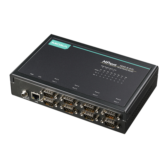
Page 10: Panel Layout (Dt And Dt-J Models)
NPort 5600-8-DT/DTL Series Overview of Hardware Panel Layout (DT and DT-J models) NOTE The figures in this section apply to the following DT and DT-J models: • NPort 5610-8-DT • NPort 5610-8-DT-J • NPort 5650-8-DT • NPort 5650-8-DT-J • NPort 5650I-8-DT Top and Rear Views Front Views NPort 5610-8-DT, 5650-8-DT, 5650I-8-DT... -
Page 11: Bottom View
NPort 5600-8-DT/DTL Series Overview of Hardware NPort 5610-8-DT-J, 5650-8-DT-J Bottom View Item Description PWR LED Indicates power input status (red) Ready and Fault LEDs Indicates normal operation (green) or IP conflict (red) Link LED Flashes when Ethernet is connected InUse LEDs Flashes when device port is transmitting or receiving data (green) Device port Tx LEDs Flashes when device port is transmitting data (green) -
Page 12: Panel Layout (Dtl And Dtl-T Models)
NPort 5600-8-DT/DTL Series Overview of Hardware Panel Layout (DTL and DTL-T models) NOTE The figures in this section apply to the following DTL and DTL-T models: • NPort 5610-8-DTL • NPort 5650-8-DTL • NPort 5650I-8-DTL • NPort 5610-8-DTL-T • NPort 5650-8-DTL-T •... -
Page 13: Bottom View
NPort 5600-8-DT/DTL Series Overview of Hardware Bottom View Item Description PWR LED Indicates power input status (red) Ready and Fault LEDs Indicates normal operation (green) or IP conflict (red) Link LED Flashes when Ethernet is connected InUse LEDs Flashes when device port is transmitting or receiving data (green) Device port Tx LEDs Flashes when device port is transmitting data (green) Device port Rx LEDs... -
Page 14: Ethernet Port Indicators
NPort 5600-8-DT/DTL Series Overview of Hardware Ethernet Port Indicators Two LED indicators are built into each 10/100M Ethernet connector. A valid network connection will be indicated as follows: A green LED indicates a valid connection to a 100 Mbps Ethernet network. An orange LED indicates a valid connection to a 10 Mbps Ethernet network. -
Page 15: Console Port Pinouts (Applies Only To Dt Models)
NPort 5600-8-DT/DTL Series Overview of Hardware – – The NPort 5610-8-DT-J only supports RS-232 signals. Console Port Pinouts (applies only to DT models) RJ45 Connector RS-232 Product Specifications NPort 5600-8-DT Ethernet Interface Number of Ports: 2 (1 IP) Speed: 10/100 Mbps, auto MDI/MDIX Connector: 8-pin RJ45 Magnetic Isolation Protection: 1.5 KV built-in Serial Interface... - Page 16 NPort 5600-8-DT/DTL Series Overview of Hardware Network Protocols: ICMP, IP, TCP, UDP, DHCP, BOOTP, Telnet, DNS, SNMP V1, HTTP, SMTP, SNTP, Rtelnet, ARP, RFC2217 Configuration Options: Web Console, Telnet Console, Serial Console, Windows Utility Windows Real COM Drivers: Windows 95/98/ME/NT/2000, Windows XP/2003/Vista/2008/7/8 x86/x64, Windows 2012 x64, Embedded CE 5.0/6.0, XP Embedded Fixed TTY Drivers: SCO Unix, SCO OpenServer, UnixWare 7, UnixWare 2.1, SVR 4.2, QNX 4.25, QNX 6, Solaris 10, FreeBSD, AIX 5.x, HP-UX 11i...
-
Page 17: Nport 5600-8-Dtl
NPort 5600-8-DT/DTL Series Overview of Hardware NPort 5600-8-DTL Ethernet Interface Number of Ports: 1 Speed: 10/100 Mbps, auto MDI/MDIX Connector: 8-pin RJ45 Magnetic Isolation Protection: 1.5 KV built-in Serial Interface Number of Ports: 8 Serial Standards: NPort 5610-8-DTL: RS-232 NPort 5650-8-DTL/5650I-8-DTL: RS-232/422/485 Connector: DB9 male Serial Line Protection: 15 KV ESD protection for all signals... - Page 18 NPort 5600-8-DT/DTL Series Overview of Hardware Storage Temperature: -40 to 85°C (-40 to 185°F) Ambient Relative Humidity: 5 to 95% (non-condensing) Power Requirements Input Voltage: 12 to 48 VDC Power Consumption: NPort 5610-8-DTL: 340 mA @ 12 V, 180 mA @ 24 V, 110 mA @ 48 V NPort 5650-8-DTL: 470 mA @ 12 V, 250 mA @ 24 V, 140 mA @ 48 V NPort 5650I-8-DTL:...
-
Page 19: Basic Installation
Basic Installation NPort 5600-8-DT/DTL device servers are designed to coordinate between your network, your host computer, and your serial device. Installation of the device server should occur in stages to ensure that each connection is recognized. This chapter will guide you through a typical installation with a Windows PC. For certain applications or environments, you may be guided to other chapters for additional information. -
Page 20: Before You Begin
NPort 5600-8-DT/DTL Series Basic Installation Before You Begin This chapter will walk you through the major steps of a typical installation and will offer advice on adjustments and options for specific applications. Please note that certain procedures will vary for your specific application and environment. -
Page 21: Step 1: Connect Network, Serial Device, And Power
NPort 5600-8-DT/DTL Series Basic Installation ATTENTION Wiring Safety Precautions: Disconnect power source Do not install or wire this unit or any attached devices with the power connected. Disconnect the power before installation by removing the power cord before installing and/or wiring your unit. Follow maximum current ratings Calculate the maximum possible current in each power wire and common wire. -
Page 22: Connect Power
NPort 5600-8-DT/DTL Series Basic Installation • NPort 5600-8-DTL: Remove the top cover to access the DIP switches used to configure each device port’s pull high/low resistors (note that SW4 is reserved for future use). The pull high/low resistor values for each device port are set as follows: Pull High Pull Low Terminator... -
Page 23: Search For Device Server On Lan
NPort 5600-8-DT/DTL Series Basic Installation Search for Device Server on LAN In NPort Administrator, click “Search” to search your LAN for NPort device servers. When your unit appears in the search results, you may click “Stop” to end the search. You may also wait a few more moments for the search to complete. -
Page 24: Verify Network Settings
NPort 5600-8-DT/DTL Series Basic Installation or “DHCP/BOOTP”, depending on your network environment. The “IP Address” and “Netmask” parameters will be unavailable for editing since these parameters will be assigned automatically. If you are not sure whether you need to configure your device server for a dynamic or static IP address, consult the administrator who set up the LAN. - Page 25 NPort 5600-8-DT/DTL Series Basic Installation Set the operation mode and associated parameters as necessary. Please refer to Chapter 5 and 6 for additional information on operation modes and advanced settings. When you are ready to restart the device server with the new settings, click “OK”. www.ipc2u.ru www.moxa.pro...
- Page 26 NPort 5600-8-DT/DTL Series Basic Installation Operation Mode Selection Chart You can use this chart to help you select the appropriate operation mode for your application. Using legacy COM Start software? Need more COM ports? Using Real COM Moxa mode with driver? Using socket Moxa driver...
-
Page 27: Step 4: Configure Serial Communication Parameters
NPort 5600-8-DT/DTL Series Basic Installation STEP 4: Configure serial communication parameters This step covers the configuration of each device port’s serial communication parameters, such as baudrate, stop bit, etc. This step requires the following items: • NPort 5600-8-DT/DTL device server with live connection to the network •... -
Page 28: Step 5: Map Com Port To Device
NPort 5600-8-DT/DTL Series Basic Installation Make adjustments to the parameters as necessary. When you are ready to restart the device server with the new settings, click “OK”. STEP 5: Map COM port to device This step covers the mapping of COM ports on a Windows PC to NPort device ports. This allows Windows software to access serial devices over the network as if they were local COM devices, for instant device networking without software migration. -
Page 29: Specify Target Device Server
NPort 5600-8-DT/DTL Series Basic Installation Specify Target Device Server In NPort Administrator, click “COM Mapping” in the Function panel to open the COM Mapping window. Right-click an empty line in the COM Mapping window and select “Add Target” in the context menu to assign your device server as the mapping target. -
Page 30: Apply Change
NPort 5600-8-DT/DTL Series Basic Installation In the Serial Parameters tab, adjust the settings to match your device. These settings , used for serial printer only, must also match the settings on the device port. Click “OK” when you are satisfied with your changes. Advanced Settings For additional details on Advanced Settings in NPort Administrator, please refer to Chapter 8. -
Page 31: General Settings
General Settings NPort 5600-8-DT/DTL device servers are easily configured to suit your network environment and your application. This chapter covers general settings for your device server. The following topics are covered in this chapter: Overview Basic Settings Network Settings ... -
Page 32: Overview
NPort 5600-8-DT/DTL Series General Settings Overview The NPort 5600-8-DT/DTL can be configured through NPort Administrator, the web console, the Telnet console, or the serial console. For each of these configuration interfaces, parameters are organized by type. For this chapter, screenshots from the web console are used to illustrate the available parameters, but the same parameters can be modified using the other interfaces. -
Page 33: Network Settings
NPort 5600-8-DT/DTL Series General Settings Telnet console (default = Enable): This field enables or disables access to the Telnet console. LCM password protect (default = No): This field enables or disables password protection for the LCM console. The LCM console refers to the LCD control panel on the top panel of the device server, which may be used for basic configuration. - Page 34 NPort 5600-8-DT/DTL Series General Settings IP address of the default gateway computer in order to communicate with the hosts outside the local network environment. Consult your network administrator if you do not know how to set this parameter. IP configuration (default = Static): This field determines how the device server’s IP address will be assigned. Four options are available: Option Description...
-
Page 35: Serial Settings
NPort 5600-8-DT/DTL Series General Settings Serial Settings Serial Settings is where you set the serial communication parameters for each device port, such as baudrate, parity, and flow control. Each device port can be configured independently. ATTENTION It is critical that the device port’s serial communication settings match the attached device. Please refer to the user’s manual for your device to verify the serial communication settings. -
Page 36: Operating Settings
NPort 5600-8-DT/DTL Series General Settings Operating Settings Operating Settings is where each device port’s operation mode and associated parameters are configured. Please refer to Chapters 5 and 6 for an explanation of the different operating modes and parameters. Accessible IP Settings The Accessible IP list allows you enable only certain IP addresses to connect to the NPort device server and attached devices. -
Page 37: Auto Warning Settings
NPort 5600-8-DT/DTL Series General Settings The following table shows additional examples: Allowed hosts IP Address setting Netmask setting Any host (disable) (disable) 192.168.1.120 192.168.1.120 255.255.255.255 192.168.1.1 to 192.168.1.254 192.168.1.0 255.255.255.0 192.168.0.1 to 192.168.255.254 192.168.0.0 255.255.0.0 192.168.1.1 to 192.168.1.126 192.168.1.0 255.255.255.128 192.168.1.129 to 192.168.1.254 192.168.1.128 255.255.255.128... -
Page 38: Event Type
NPort 5600-8-DT/DTL Series General Settings SNMP trap server (default = blank): This optional field is for the IP address or domain name of your SNMP trap server, if applicable. The SNMP trap server is required for the NPort to send SNMP traps for certain administrative events. -
Page 39: Change Password
NPort 5600-8-DT/DTL Series General Settings DSR changed, Ports 1 through 8: The device port’s DSR (Data Set Ready) signal has changed, or the attached device has no power. For example, a DSR change to high indicates that the DCE (Data Communication Equipment) is powered on. -
Page 40: Introduction To Operation Modes
Introduction to Operation Modes In this chapter, we describe the various device port operation modes available on NPort 5600-8-DT/DTL device servers. The operation mode determines how the device port will interact with the network. The selection of operation mode will depend on your specific application. After choosing the proper operation mode in this chapter, please refer to Chapter 6 for information on configuring the operation mode advanced settings. -
Page 41: Overview
NPort 5600-8-DT/DTL Series Introduction to Operation Modes Overview The NPort 5600-8-DT/DTL connects RS-232/422/485 devices to an Ethernet network. In a typical application, a traditional SCADA and data collection system relies on serial devices to collect data from various kinds of instruments. -
Page 42: Rfc2217 Mode
NPort 5600-8-DT/DTL Series Introduction to Operation Modes ATTENTION In Real COM mode, several hosts can have simultaneous access control over the device port. If necessary, you can limit access by using the Accessible IP settings. Please refer to Chapter 4 for additional information about Accessible IP settings. -
Page 43: Udp Mode
NPort 5600-8-DT/DTL Series Introduction to Operation Modes UDP Mode UDP is similar to TCP but is faster and more efficient. Data can be broadcast to or received from multiple network hosts. However, UDP does not support verification of data and would not be suitable for applications where data integrity is critical. -
Page 44: Operation Mode Advanced Settings
Operation Mode Advanced Settings Each device port on NPort 5600-8-DT/DTL device servers operate in one of the available operation modes, such as Real COM mode or Reverse Telnet mode. For each operation mode, different parameters can be configured. This chapter explains the settings for every parameter for every operation mode. The following topics are covered in this chapter: ... -
Page 45: Overview
NPort 5600-8-DT/DTL Series Operation Mode Advanced Settings Overview The device port operation mode determines how the port interacts with the network. Depending on your application and device, more than one operating mode may be suitable. When setting the operation mode, different parameters may be adjusted depending on the operation mode. -
Page 46: Using Pair Connection Modes
NPort 5600-8-DT/DTL Series Operation Mode Advanced Settings • You are using Pair Connection modes to connect two serial devices over Ethernet. Adjust Local TCP port and Destination IP Address. Using Pair Connection Modes For some applications, you may simply want a serial device to communicate directly to another serial device over the network. -
Page 47: Data Packing Parameters
NPort 5600-8-DT/DTL Series Operation Mode Advanced Settings Max connection Range: 1 to 4 Default: 1 Description: This specifies the maximum number of simultaneous connections that the port will accept. When adjusting Max connection, make sure that Ignore jammed IP and Allow driver control are also adjusted correctly. - Page 48 NPort 5600-8-DT/DTL Series Operation Mode Advanced Settings Delimiter 1 and 2 Range: 0 to FF, Enable Default: Disabled Description: This controls data packing by special delimiter character(s). Serial data accumulates in the device port’s buffer until the delimiter character(s) are received, after which the data is packed for network transmission.
-
Page 49: Other Parameters
NPort 5600-8-DT/DTL Series Operation Mode Advanced Settings Other Parameters Local TCP port Range: 1 to 65535 Default: 4001 for port 1, 4002 for port 2, etc. Description: This specifies the TCP port number for communication to the attached device. - Page 50 NPort 5600-8-DT/DTL Series Operation Mode Advanced Settings Local listen port Range: 1 to 65535 Default: 4001 for port 1, 4002 for port 2, etc. Description: This specifies the UDP port number for network communication to the serial device. Socket applications will need to refer to the device using this port number.
-
Page 51: Using The Web Console
Using the Web Console The NPort 5600-8-DT/DTL web console allows it to be managed from anywhere on the network using a standard web browser. This chapter explains how to use the web console. The following topics are covered in this chapter: ... -
Page 52: Overview
NPort 5600-8-DT/DTL Series Using the Web Console Overview The NPort can be configured from anywhere on the network through its web console. Simply point the browser to the device server’s IP address to open the web console. Network settings, operation mode, and other items can all be modified through the browser. -
Page 53: Basic Navigation
NPort 5600-8-DT/DTL Series Using the Web Console Basic Navigation To open the web console, enter your device server’s IP address in the website address line. If you are configuring the NPort for the first time, you will use the default IP address, 192.168.127.254. If prompted, enter the console password. -
Page 54: Device Server Settings
NPort 5600-8-DT/DTL Series Using the Web Console Device Server Settings Please refer to Chapter 4 for details on the following settings: • Basic Settings • Network Settings • Serial Settings • Accessible IP Settings • Auto Warning Settings • Change Password •... -
Page 55: Load Factory Defaults
NPort 5600-8-DT/DTL Series Using the Web Console Async-Settings Monitor each device port’s serial run-time settings. Load Factory Defaults This will load the NPort’s factory default configuration. All parameters will be reset, and the current configuration settings will be lost. It is strongly recommended that you first save your configuration to a file so that it can be restored if necessary. -
Page 56: Using Nport Administrator
Using NPort Administrator The following topics are covered in this chapter: Overview Installing NPort Administrator Basic Navigation Window Layout Activating a Function Configuration Finding Your Device Server Status Device Server Parameters ... -
Page 57: Overview
NPort 5600-8-DT/DTL Series Using NPort Administrator Overview The NPort Administration Suite provides everything you need to manage, monitor, and modify your NPort from a remote location. It includes NPort Administrator and the IP Serial Library. With NPort Administrator, you can easily install and configure your NPort device server over the network. You can also run NPort Administrator from one location to manage multiple device servers. - Page 58 NPort 5600-8-DT/DTL Series Using NPort Administrator 3. Click Next to accept the proposed Start menu folder, or select a different folder. 4. Click Install to proceed with the installation. 5. The setup wizard will show the progress of the installation. www.ipc2u.ru www.moxa.pro...
- Page 59 NPort 5600-8-DT/DTL Series Using NPort Administrator 6. A special notice will appear. Click Next after reading the notice. 7. Click Finish to complete the installation of the NPort Administration Suite. www.ipc2u.ru www.moxa.pro...
-
Page 60: Basic Navigation
NPort 5600-8-DT/DTL Series Using NPort Administrator Basic Navigation Window Layout NPort Administrator is designed to make it easy to configure, monitor, or manage any NPort 5600-8-DT/DTL on your network. The interface is organized into four areas as follows: • The top section is the menu area. •... -
Page 61: Configuration
NPort 5600-8-DT/DTL Series Using NPort Administrator 3. Once your device server is on the list for the desired function, right-click the target device server to open the function context menu. Activate the desired command from this context menu. You may also select the target device server and then open the function context menu from the menu bar. -
Page 62: Status
NPort 5600-8-DT/DTL Series Using NPort Administrator Status The NPort may be password-protected to prevent unauthorized configuration changes. Please refer to Chapter 4 for additional information on password protection. The status will be shown in the list of available device servers. There are six possible statuses for device servers on the network. Status Description Lock... -
Page 63: Device Server Parameters
NPort 5600-8-DT/DTL Series Using NPort Administrator 4. The device server’s status will be updated to “Unlock”. Device Server Parameters You can configure any NPort 5600-8-DT/DTL on the LAN using the Assign IP Address, Configure, orWeb commands in the function context menu. Assign IP Address: This allows you to set the target NPort’s IP address quickly, instead of digging through pages of configuration parameters. - Page 64 NPort 5600-8-DT/DTL Series Using NPort Administrator ATTENTION You can configure multiple units simultaneously, as long as the units are the same model. Simply hold down the Ctrl or Shift key when selecting the target device servers. Web: This opens the target device server’s web console. Please refer to Chapter 7 for details on using the web console.
-
Page 65: Firmware And Configuration Management
NPort 5600-8-DT/DTL Series Using NPort Administrator Firmware and Configuration Management You can manage your device servers’ firmware and configuration using the Upgrade Firmware and Import/Export Configuration commands. Upgrade Firmware: This allows you to upload new firmware to the target NPort device server. You can obtain firmware updates for your NPort 5600-8-DT/DTL at www.moxa.com. -
Page 66: Monitor
NPort 5600-8-DT/DTL Series Using NPort Administrator Follow the onscreen instructions to save or restore the target unit’s configuration. ATTENTION You can import the configuration of multiple units simultaneously, as long as the units are the same model. Simply hold down the Ctrl or Shift key when selecting the target device servers. Monitor You can use NPort Administrator for live monitoring of your NPort over the network. -
Page 67: Monitoring Parameters
NPort 5600-8-DT/DTL Series Using NPort Administrator Monitoring Parameters The Settings command specifies which items of information will be monitored, how often the information is refreshed, and how notification of events will occur. In the Monitor Items tab, you may select which items of information will be monitored. 8-12 www.ipc2u.ru www.moxa.pro... -
Page 68: Activating The Monitor
NPort 5600-8-DT/DTL Series Using NPort Administrator In the General Settings tab, you may select the monitoring refresh rate, which is how often the monitor function will check the status of each NPort on the monitor list. The default is 3 seconds. Activating the Monitor The Go command activates live monitoring. - Page 69 NPort 5600-8-DT/DTL Series Using NPort Administrator If you configured the monitor function with warnings enabled, a notification will appear if a monitored device server goes off-line. NPorts that are off-line will be also displayed in red in the monitor list. If the NPort is able to re-establish the connection, another notification will appear indicating that the NPort 5600-8-DT/DTL is now “Alive.”...
-
Page 70: Port Monitor
NPort 5600-8-DT/DTL Series Using NPort Administrator Select the Stop command to suspend live monitoring. Port Monitor The Port Monitor function is identical to the Monitor function, but with many additional items that can be monitored, as shown below. In addition, each item on the port monitor list will be an individual device port on an NPort device server. Each device port can be selected or deselected for monitoring. -
Page 71: Finding Your Device Server
NPort 5600-8-DT/DTL Series Using NPort Administrator ATTENTION A device port must be operating in Real COM mode in order to be used in COM mapping. Finding Your Device Server If the list of available servers is empty, find your device server on the network using the Add Target command in the function context menu. -
Page 72: Com Mapping Settings
NPort 5600-8-DT/DTL Series Using NPort Administrator COM Mapping Settings Each item on the COM mapping list refers to an individual device port on an NPort device server. To map a COM port to a listed device port, right-click the target device port and select COM Settings in the function context menu. - Page 73 NPort 5600-8-DT/DTL Series Using NPort Administrator Tx Mode Hi-Performance is the default for Tx mode. After the driver sends data to the NPort, the driver immediately issues a “Tx Empty” response to the program. Under Classical mode, the driver will not send the “Tx Empty” response until after confirmation is received from the NPort.
-
Page 74: Saving Com Mapping Settings
NPort 5600-8-DT/DTL Series Using NPort Administrator Saving COM Mapping Settings After mapping COM ports to NPort device ports, you will need to save the COM mapping settings to the Real COM driver. Use the Apply Change command in the function context menu to save the mapping settings; use the Discard Change command to delete the changes. -
Page 75: Com Grouping
NPort 5600-8-DT/DTL Series Using NPort Administrator COM Grouping The “COM Grouping” function is designed to simulate the multi-drop behavior of serial communication over an Ethernet network. COM Grouping allows you to create a COM Group and redirect data from it to several physical COM ports on NPort device servers. - Page 76 NPort 5600-8-DT/DTL Series Using NPort Administrator 3. Select the Grouping selected port(s) together checkbox. 4. On the COM Grouping page, you can set “Read” and “Write” permissions for every serial port. It is necessary to set Signal Status in order to control the data transmission with specified control signals (e.g., DTR/RTS).
-
Page 77: Deleting A Com Group
NPort 5600-8-DT/DTL Series Using NPort Administrator Deleting a COM Group Follow the steps below to delete a COM Group and then auto-assign COM numbers for each port in the Group: 1. Select all serial ports in the Group you are deleting and then right-click to select COM Settings. 2. -
Page 78: Adding A Port To A Com Group
NPort 5600-8-DT/DTL Series Using NPort Administrator Adding a Port to a COM Group Follow the steps below to add a serial port into an existing COM Group: 1. Select the serial port that you are adding and right-click to select COM Settings. 2. -
Page 79: Removing A Port From A Com Group
NPort 5600-8-DT/DTL Series Using NPort Administrator Removing a Port from a COM Group Follow the steps below to remove a serial port from a COM Group: 1. Select a serial port in the Group and right-click to select COM Settings. 2. -
Page 80: Modifying Ports In A Com Group
NPort 5600-8-DT/DTL Series Using NPort Administrator Modifying Ports in a COM Group In the following subsections we examine three ways in which the serial ports in a COM Group can be modified: Changing the COM Number of a COM Group 1. - Page 81 NPort 5600-8-DT/DTL Series Using NPort Administrator 4. You will be able to view the serial ports that were assigned to and removed from the Group. Click Apply to apply the settings. 5. Finally, click Yes to confirm. Changing Advanced Settings and Serial Parameters of the COM Group 1.
- Page 82 NPort 5600-8-DT/DTL Series Using NPort Administrator 3. The Advanced Settings and Serial Parameters pages will be available for modification. Changing the Serial Port Specified as Signal Port for the COM Group 1. Selecta serial port in the Group and then right-click and select COM Settings. 8-27 www.ipc2u.ru www.moxa.pro...
-
Page 83: Ip Address Report
NPort 5600-8-DT/DTL Series Using NPort Administrator 2. Check the Grouping selected port(s) together check box. 3. On COM Grouping page, you can specify one serial port whose signals will be taken into account by the COM Group and change the Read/Write status for each serial port. IP Address Report The IP Address Report function receives automatic IP reports from appropriately configured NPort device servers. -
Page 84: Automatic Message Log
NPort 5600-8-DT/DTL Series Using NPort Administrator On the NPort device server, the Auto report to IP parameter must be set to the IP address of the PC that is running NPort Administrator. Select Go from the function context menu to begin monitoring for IP address reports. The IP Address Report window will begin displaying IP reports as they are received. -
Page 85: Nport Ce Driver Manager For Windows Ce
NPort CE Driver Manager for Windows CE The following topics are covered in this chapter: Overview Installing NPort CE Driver Manager Using NPort CE Driver Manager www.ipc2u.ru www.moxa.pro... -
Page 86: Overview
NPort 5600-8-DT/DTL Series NPort CE Driver Manager for Windows CE Overview NPort CE Driver Manager is designed for use with NPort 5000 serial ports that are set to Real COM mode. The software manages the installation of drivers that allow you to map unused COM ports on your PC to serial ports on the NPort 5000. - Page 87 NPort 5600-8-DT/DTL Series NPort CE Driver Manager for Windows CE Click on the COM Mapping page and then the “Search” button to scan for NPort servers. All NPort servers that were located will appear in the NPort CE Driver Manager window. Click on the server whose COM ports you would like to map to and then select the port index.
- Page 88 NPort 5600-8-DT/DTL Series NPort CE Driver Manager for Windows CE To configure the settings for a particular COM Port, select the row of the desired port, and then modify the setting in the “Settings” panel, as shown below. Tx Mode “Hi-Performance”...
-
Page 89: Other Configuration Interfaces
Other Configuration Interfaces The following topics are covered in this chapter: Overview LCM Console (applies to DT models only) Main Menu Server setting Main Menu Network setting Main Menu Serial set Main Menu Op Mode set ... -
Page 90: Overview
NPort 5600-8-DT/DTL Series Other Configuration Interfaces Overview Typically, you will use either NPort Administrator or the web console to configure the NPort 5600-8-DT/DTL. These are not the only options for configuration. For basic onsite configuration, you can use the LCM console built into the device server, without requiring a connection to the network or a laptop. -
Page 91: Main Menu Op Mode Set
NPort 5600-8-DT/DTL Series Other Configuration Interfaces Main Menu Op Mode set Under Op Mode set, you can view or modify each device port’s operation mode. You will first select the port that you wish to modify or view. Note that you can only select the operation mode. You will not be able to view or modify the advanced operation mode settings through the LCM console. -
Page 92: Serial Console (Nport 5600-8-Dtl)
NPort 5600-8-DT/DTL Series Other Configuration Interfaces Serial Console (NPort 5600-8-DTL) You may use the RS-232 console port to set up the IP address for NPort 5600-8-DTL. We suggest using PComm Terminal Emulator, which is available free of charge as part of the PComm Lite program suite (found on the Software CD that comes with the product), to carry out the installation procedure, although other similar utilities may also be used. - Page 93 NPort 5600-8-DT/DTL Series Other Configuration Interfaces 10-5 www.ipc2u.ru www.moxa.pro...
-
Page 94: Tty Drivers For Linux And Unix
TTY Drivers for Linux and UNIX The following topics are covered in this chapter: Linux Real TTY Drivers Basic Steps Installing Linux Real TTY Driver Files Mapping TTY Ports Removing Mapped TTY Ports Removing Linux Driver Files ... -
Page 95: Linux Real Tty Drivers
NPort 5600-8-DT/DTL Series TTY Drivers for Linux and UNIX Linux Real TTY Drivers Real TTY driver are provided that will map Linux host TTY ports to NPort device ports. Once the mapping has been set up, Linux users and applications can connect to a device port as if it were a local TTY port. These drivers have been designed and tested for the majority of Linux distributions, including Linux kernel version 2.4.x and 2.6.x. -
Page 96: Removing Mapped Tty Ports
NPort 5600-8-DT/DTL Series TTY Drivers for Linux and UNIX The mxaddsvr command performs the following actions: 1. Modify npreal2d.cf. 2. Create TTY ports in directory /dev with major and minor number configured in npreal2d.cf. 3. Restart the driver. Mapping TTY ports automatically To map TTY ports automatically, you may execute mxaddsvr with just the IP address and number of ports, as in the following example: # cd /usr/lib/npreal2/driver... -
Page 97: Unix Fixed Tty Drivers
NPort 5600-8-DT/DTL Series TTY Drivers for Linux and UNIX UNIX Fixed TTY Drivers A fixed TTY driver is provided that will map UNIX host TTY ports to NPort device ports. Once the mapping has been set up, UNIX users and applications can connect to a device port as if it were a local TTY port. This driver has been designed and tested for the majority of UNIX systems. - Page 98 NPort 5600-8-DT/DTL Series TTY Drivers for Linux and UNIX The value of [n] should be equal or larger than 11 in order to prevent conflicts with the device names of functional keys in some UNIX systems. Starting moxattyd Execute the command init q or reboot your UNIX operating system. Adding an additional server Modify the text file moxattyd.cf to add an additional server.
-
Page 99: The Ip Serial Library
The IP Serial Library The following topics are covered in this chapter: Overview IP Serial Library Function Groups Example Program www.ipc2u.ru www.moxa.pro... -
Page 100: Overview
NPort 5600-8-DT/DTL Series The IP Serial Library Overview What is the IP Serial Library? The IP Serial Library is a Windows library with frequently used serial command sets and subroutines. It is designed to reduce the complexity and improve the efficiency of serial communication over TCP/IP. For example, Telnet can transfer data but cannot monitor or configure the serial line’s parameters. -
Page 101: Example Program
NPort 5600-8-DT/DTL Series The IP Serial Library Example Program char nportip=“192.168.1.10”; /*data buffer, 255 chars */ char buffer[255]; /*1st port */ int port = 1; int portid; nsio_init(); /* port handle */ portid = nsio_open(nportip, port); nsio_ioctl(portid, /*initial IP Serial Library */ B9600, (BIT_8 | STOP_1 | P_NONE) );... -
Page 102: Troubleshooting
Troubleshooting In this chapter, we describe a straightforward procedure that can be used to troubleshoot problems you encounter when operating your NPort. We recommend that you follow these step by step instructions first before contacting Moxa’s technical support team. Connection Problems Step 1: Does the Ethernet LED light up? If not, try the following: •... -
Page 103: Tcp Server Mode
NPort 5600-8-DT/DTL Series Troubleshooting • For NAT environments, use NAT port mapping. • Verify that ping response time is less than 1000 ms. • Go over the installation procedures again in the user’s manual. Step 2: Are you able to open the device port on the NPort? If not, try the following: •... -
Page 104: Serial Data Problems
NPort 5600-8-DT/DTL Series Troubleshooting Serial Data Problems Try the following measures: • Make sure there are no cable wiring issues. 3 or 8-wire cabling should be used for RS-232, point-to-point 4-wire cabling for RS-422, and daisy-chain 2 or 4-wire cabling for RS-485. •... -
Page 105: Cable Wiring
Cable Wiring The following topics are covered in this appendix: RS-232 Cables RS-422, 4-wire RS-485 Cables 2-wire RS-485 Cables www.ipc2u.ru www.moxa.pro... -
Page 106: Rs-422, 4-Wire Rs-485 Cables
NPort 5600-8-DT/DTL Series Cable Wiring RS-232 Cables NPort Serial Device RJ45 DB9(F) DB9(M) DB25(M) DB25(F) RS-422, 4-wire RS-485 Cables NPort Serial Device RJ45 DB9(F) DB9(M) DB25(M) DB25(F) TxD+ RxD+ TxD- RxD- RxD+ TxD+ RxD- TxD- 2-wire RS-485 Cables NPort Serial Device RJ45 DB9(F) DB9(M) - Page 107 SNMP Agent with MIB II & RS-232-Like Group SNMP (Simple Network Management Protocol) agent software is built into the NPort 5600-8-DT/DTL. It supports SNMP Trap, the RFC1317 RS-232-like group, and RFC1213 MIB-II. The following table lists the standard MIB-II group and the variable implementation for the NPort 5600-8-DT/DTL. RFC1213 MIB-II supported SNMP variables: System MIB Interfaces MIB...
-
Page 108: Snmp Agent With Mib Ii & Rs-232-Like Group
NPort 5600-8-DT/DTL Series SNMP Agent with MIB II & RS-232-Like Group UDP MIB TCP MIB SNMP MIB UdpInDatagrams tcpRtoAlgorithm snmpInPkts UdpNoPorts tcpRtoMin snmpOutPkts UdpInErrors tcpRtoMax snmpInBadVersions UdpOutDatagrams tcpMaxConn snmpInBadCommunityNames UdpLocalAddress tcpActiveOpens snmpInASNParseErrs UdpLocalPort tcpPassiveOpens snmpInTooBigs tcpAttempFails snmpInNoSuchNames Address Translation MIB tcpEstabResets snmpInBadValues AtIfIndex... - Page 109 NPort 5600-8-DT/DTL Series SNMP Agent with MIB II & RS-232-Like Group Input Signal Table Output Signal Table rs232InSigTable rs232OutSigTable rs232InSigEntry rs232OutSigEntry rs232InSigPortIndex rs232OutSigPortIndex rs232InSigName rs232OutSigName rs232InSigState rs232OutSigState www.ipc2u.ru www.moxa.pro...
-
Page 110: Ip Report Protocol
IP Report Protocol There are several ways to configure the IP address of the NPort device server. One of them is DHCP Client. When you set up the device server to use DHCP Client for IP address configuration, it will automatically send a DHCP request over the network to find the DHCP server. -
Page 111: Hardware And Ap Id
NPort 5600-8-DT/DTL Series IP Report Protocol Hardware and AP ID Each model is assigned a Hardware ID and AP ID as shown below: Hardware ID AP ID Product 0x5700 0x80015610 5610-8-DT 0x5702 0x80015610 5650-8-DT 0x5703 0x80015610 5650I-8-DT 0x5704 0x80015610 5610-8-DT-J 0x5706 0x80015610 5650-8-DT-J... -
Page 112: Compliance Notice
Compliance Notice CE Warming This is a Class A product. In a domestic environment, this product may cause radio interference in which case the user may be required to take appropriate measures. Federal Communications Commission Statement FCC - This device complies with part 15 of the FCC Rules. Operation is subject to the following two conditions: (1) This device may not cause harmful interference, and (2) this device must accept any interference received, including interference that may cause undesired operation.
Need help?
Do you have a question about the NPort 5600-8-DT Series and is the answer not in the manual?
Questions and answers