
Related Manuals for ATEN CL3800


Summary of Contents for ATEN CL3800
- Page 1 Short Depth WideScreen LCD Console CL3800 / CL3700 / CL3100 User Manual www.aten.com...
-
Page 2: Emc Information
CL3800 / CL3700 / CL3100 User Manual EMC Information FEDERAL COMMUNICATIONS COMMISSION INTERFERENCE STATEMENT: This equipment has been tested and found to comply with the limits for a Class A digital device, pursuant to Part 15 of the FCC Rules. These limits are designed to provide reasonable protection against harmful interference when the equipment is operated in a commercial environment. -
Page 3: User Information
CL3800 / CL3700 / CL3100 User Manual User Information Online Registration Be sure to register your product at our online support center: International http://eservice.aten.com Telephone Support For telephone support, call this number: International 886-2-8692-6959 China 86-400-810-0-810 Japan 81-3-5615-5811 Korea 82-2-467-6789... -
Page 4: User Notice
CL3800 / CL3700 / CL3100 User Manual User Notice All information, documentation, and specifications contained in this manual are subject to change without prior notification by the manufacturer. The manufacturer makes no representations or warranties, either expressed or implied, with respect to the contents hereof and specifically disclaims any warranties as to merchantability or fitness for any particular purpose. -
Page 5: Package Contents
CL3800 / CL3700 / CL3100 User Manual Package Contents CL3800 1 CL3800 USB HDMI DVI VGA Dual Rail LCD Console with Standard Rack Mount Kit 1 USB HDMI KVM Cable Set 1 Firmware Upgrade Cable 1 Power Cord 2 Front-L Brackets... - Page 6 © Copyright 2020 ATEN® International Co., Ltd. Manual Date: 2020-08-19 ATEN and the ATEN logo are registered trademarks of ATEN International Co., Ltd. All rights reserved. All other brand names and trademarks are the registered property of their respective owners.
-
Page 7: Table Of Contents
Connecting Up - CL3800........ - Page 8 CL3800 ........
-
Page 9: About This Manual
CL3800 / CL3700 / CL3100 User Manual About this Manual This User Manual is provided to help you get the most from your CL3800 / CL3700 / CL3100 system. It covers all aspects of installation, configuration and operation. An overview of the information found in the manual is provided below. -
Page 10: Conventions
For information about all ATEN products and how they can help you connect without limits, visit ATEN on the Web or contact an ATEN Authorized Reseller. Visit ATEN on the Web for a list of locations and telephone numbers: International http://www.aten.com... -
Page 11: Chapter 1 Introduction
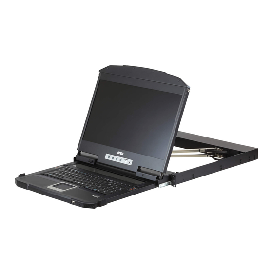
(OB vans) and compact control rooms. The CL3800 USB HDMI DVI VGA LCD Console is a dual rail LCD KVM console featuring an 18.5" LED-backlit widescreen LCD monitor with an integrated keyboard and touchpad. The CL3800 supports three types of video input –... -
Page 12: Rear Panel External Console Ports
ATEN website. Setup is fast and easy. Simply use the custom cable included with your device to connect the CL3800 / CL3700 / CL3100 to the console ports of your KVM switch and you are ready to go! -
Page 13: Features
1U high system rack (CL3700 and CL3100) Supports three types of video input – HDMI, DVI, and VGA*; supports an external console with USB / HDMI / VGA / DVI connectors* (CL3800 only) Supports HDMI video input; supports an external console with USB / HDMI connectors (CL3700 only) ... - Page 14 CL3800 / CL3700 / CL3100 User Manual Optional 2-in-1U Mounting Kit (2K-0001/2K-0002) – fitting the CL3800/ CL3700/CL3100 and a rack KVM switch in 1U of space on a rack for space-saving, easy and flexible operation Optional rack mount kits available, including easy installation options ...
-
Page 15: Requirements
Chapter 1. Introduction Requirements LCD Console The CL3800 supports most ATEN HDMI, DVI, and VGA KVM switches; the CL3700 supports most ATEN HDMI KVM switches; the CL3100 supports most ATEN VGA KVM switches. For CL3800NW and CL3700NW models, the integrated LCD monitor's maximum resolution is 1920 x 1080 @ 60 Hz;... - Page 16 CL3800 / CL3700 / CL3100 User Manual CL3700 Length (m) Type Part Number 1.80 USB, HDMI 2L-7D02UH CL3100 Length (m) Type Part Number 1.20 USB, VGA 2L-5201U, 2L-5301U 1.80 2L-5202U, 2L-5302U 3.00 2L-5203U, 2L-5303U 5.00 2L-5205U,2L-5305U...
-
Page 17: Operating Systems
Chapter 1. Introduction Operating Systems Supported operating systems include Windows, Mac, Linux, and Sun. -
Page 18: Components
CL3800 / CL3700 / CL3100 User Manual Components CL3800 Front View EXIT LIGHT... - Page 19 Chapter 1. Introduction Component Description Upper Handle Pull to slide the LCD module out; push to slide it in. See Opening / Closing the Console, page 31, for details on sliding the console in and out LCD Module After sliding the LCD module out, flip up the cover to access the LCD display.
- Page 20 CL3800 / CL3700 / CL3100 User Manual Component Description LED Illumination Illuminates the keyboard and touchpad to allow visibility in Light low-light conditions. Exit/Light Press the Exit/Light pushbutton for two seconds to turn the Pushbutton LED Illumination Light On or Off. (Default: On)
-
Page 21: Cl3800 Rear View
KVM Port The custom USB HDMI KVM cable supplied with the package Section for linking the CL3800 to a computer or switch plugs in here. Additional DVI and VGA ports are provided. Grounding The grounding wire (used to ground the unit) attaches here. -
Page 22: Cl3700 / Cl3100 Front View
CL3800 / CL3700 / CL3100 User Manual CL3700 / CL3100 Front View EXIT LIGHT... - Page 23 Chapter 1. Introduction Component Description Upper Handle Pull to slide the LCD module out; push to slide it in. With Release Bar See Opening / Closing the Console, page 31, for details on sliding the console in and out LCD Module After sliding the LCD module out, flip up the cover to access the LCD display.
-
Page 24: Cl3700 Rear View
CL3800 / CL3700 / CL3100 User Manual CL3700 Rear View Component Description Power Socket This is a standard 3 prong AC power socket. The power cord from an AC source plugs in here. Power Switch This is a standard rocker switch that powers the CL3700 on and off. -
Page 25: Cl3100 Rear View
Chapter 1. Introduction CL3100 Rear View Component Description Power Socket This is a standard 3 prong AC power socket. The power cord from an AC source plugs in here. Power Switch This is a standard rocker switch that powers the CL3100 on and off. - Page 26 CL3800 / CL3700 / CL3100 User Manual This Page Intentionally Left Blank...
-
Page 27: Chapter 2. Hardware Setup
You must unplug the power cords of any computers that have the Keyboard Power On function. 3. (CL3800 only) Packing material has been inserted to protect the CL3800 during shipping. Slide the LCD module out (see Opening / Closing the Console, page 31), until the packing material is visible. - Page 28 CL3800 / CL3700 / CL3100 User Manual 4. The LCD KVM switch is designed for rack mounting. If the KVM switch is not rack mounted be sure to place it on a completely flat and firm surface before pulling the device in or out to prevent damage due to uneven force on the module.
-
Page 29: Standard Rack Mounting
Chapter 2. Hardware Setup Standard Rack Mounting A standard rack mounting kit enables the CL3800 to be mounted in a rack with a depth of 47–75 cm. A standard rack mounting kit enables the CL3700/ CL3100 to be mounted in a rack with a depth of 42-72 cm. - Page 30 CL3800 / CL3700 / CL3100 User Manual To rack mount the CL3800 / CL3700 / CL3100, do the following: 1. Attach the left and right L-shaped brackets to the back of the rack, installing four screws in the brackets to secure them in place.
-
Page 31: Front-L Brackets Mounting (Cl3800 Only)
Chapter 2. Hardware Setup Front-L Brackets Mounting (CL3800 only) To have a comfortable and safe posture, install the Front-L Brackets which provide an extension at the front of the rack to help the unit slide further out and thus allowing you to tilt the LCD screen more. Instructions to use this option are shown below: 1. - Page 32 CL3800 / CL3700 / CL3100 User Manual 3. While one person inserts the unit into place by sliding its left and right side bars into the left and right L-shaped brackets (on the rack), have a second person screw the front brackets to the front-L bracket.
-
Page 33: Optional Rack Mount Kits
Chapter 2. Hardware Setup Optional Rack Mount Kits For convenience and flexibility, optional rack mount kits are available and are listed in the table below: Mounting Kit Description Standard Long Rack Mount This kit is the long-railed version of your standard mounting kit that lets you fit your device to racks with greater depth. -
Page 34: Connecting Up - Cl3800
(HDMI, VGA, or DVI-D) can be displayed at a time. The DVI monitor will display a DVI-D signal only. 4. Plug the CL3800’s power cord into the CL3800’s power socket and into a power source. 5. Turn on the power to LCD Console. - Page 35 Chapter 2. Hardware Setup Installation Diagram HDMI, DVI-D, or VGA CL3800 (Rear) KVM Switch (Rear)
-
Page 36: Connecting Up - Cl3700
CL3800 / CL3700 / CL3100 User Manual Connecting Up - CL3700 Refer to the example installation diagram below as you perform the following steps: 1. Plug the HDMI and USB Type B connectors of a KVM cable into the KVM ports located in the CPU section on the rear of the CL3700. - Page 37 Chapter 2. Hardware Setup Installation Diagram HDMI CL3700 (Rear) KVM Switch (Rear)
-
Page 38: Connecting Up - Cl3100
CL3800 / CL3700 / CL3100 User Manual Connecting Up - CL3100 Refer to the example installation diagram below as you perform the following steps: 1. Plug one end of the KVM cable into the KVM ports located in the CPU section on the rear of the CL3100. - Page 39 Chapter 2. Hardware Setup Installation Diagram CL3100 (Rear) KVM Switch (Rear)
- Page 40 CL3800 / CL3700 / CL3100 User Manual This Page Intentionally Left Blank...
-
Page 41: Opening / Closing The Console
Operation Opening / Closing the Console The CL3800’s console consists of two modules: an 18.5” LCD display module located under the top cover; and a keyboard / touch pad module below the LCD module. The modules can either slide together, or independently. This allows you to have the LCD display available for viewing while the keyboard / touch pad module is conveniently out of the way when not in use. - Page 42 CL3800 / CL3700 / CL3100 User Manual 2. Pulling, slide the Panel module out until it clicks in place. 3. Raise the top panel all the way back to expose the LCD screen.
- Page 43 Chapter 3. Operation 4. Use the Lower Release Bar handle to pull the keyboard module straight out unit it clicks in place. Lower Release Bar 5. To independently retract the keyboard into the rack, slide both Keyboard Module Releases and push the keyboard module all the way in.
- Page 44 CL3800 / CL3700 / CL3100 User Manual 6. Slide the keyboard in until it's completely inserted into the rack. 7. To close the LCD screen, lower the panel module until it lies flat and slide it back in.
-
Page 45: Cl3700 / Cl3100
Chapter 3. Operation CL3700 / CL3100 Refer to the diagrams below to open or close the console as you do the following: 1. Pull on the Release Bar on the upper handle. Slide the console module out until it clicks in place, and then raise the LCD Module lid. 2. -
Page 46: Operating Precautions
CL3800 / CL3700 / CL3100 User Manual Operating Precautions The maximum load bearing capacity of the keyboard module is 30 kg. Failure to heed the information below can result in damage to the keyboard module. Right! Rest your hands and arms lightly on the keyboard module as you work. -
Page 47: Lcd Osd Configuration
Chapter 3. Operation LCD OSD Configuration LCD Buttons The LCD OSD allows you to set up and configure the LCD display. Four buttons are used to perform the configuration, as described in the table, below: Button Function MENU When you have not entered the LCD OSD Menu function, pressing this button invokes the Menu function, and brings up the Main Menu. -
Page 48: Adjustment Settings
Lets you select an Analog (VGA) or Digital (HDMI, DVI) input source for connecting an external console to the CL3800. This option is not available for the CL3700 or CL3100 as they only have one input source option. See External Console Section, page 11. -
Page 49: Hot Plugging
Port ID Numbering & Port Selection If you connect a KVM switch to the CL3800 / CL3700 / CL3100, Port ID numbering and Port Selection follow the method used by the connected KVM... -
Page 50: Hotkeys
CL3800 / CL3700 / CL3100 User Manual Hotkeys Console selection is accomplished with the following hotkey combinations: Combination Action Beeps LEDs [Ctrl] [Alt] [Shift] [P] [C] To select normal mode (pc, etc.). None [Enter] [Ctrl] [Alt] [Shift] [M] [A] [C]... - Page 51 [Shift], make sure you are using the keys on the same side of the keyboard. 4. If the KVM switch connected to the CL3800 / CL3700 / CL3100 uses the [Ctrl] [Alt] [Shift] combination to invoke its hotkey mode, you won’t be able to access any of its hotkey operations because the...
- Page 52 CL3800 / CL3700 / CL3100 User Manual This Page Intentionally Left Blank...
-
Page 53: Chapter 4. Firmware Upgrade
Before You Begin To prepare for the firmware upgrade, do the following: 1. From a computer that is not part of your CL3800 / CL3700 / CL3100 installation go to ATEN’s Internet support site and choose the model name that relates to your device to get a list of available Firmware Upgrade Packages. -
Page 54: Firmware Upgrade Mode
(see page 9) must be set to the Normal position. 1. Turn off the power to the CL3800 / CL3700 / CL3100 using the power switch located on the back side of the console. 2. Slide the firmware switch to RECOVER (see page 9). -
Page 55: Performing The Upgrade
Performing the Upgrade Starting the Upgrade: 1. With the CL3800 / CL3700 / CL3100 in Firmware Upgrade Mode, run the downloaded Firmware Upgrade Package file from your computer - either by double clicking the file icon, or by opening a command line and keying in the full path and filename. - Page 56 CL3800 / CL3700 / CL3100 User Manual (Continued from previous page.) 3. Click Next. The Firmware Upgrade Utility main screen appears: The Utility inspects your installation. All the devices capable of being upgraded by the package are listed in the Device List panel.
-
Page 57: Upgrade Succeeded
Chapter 4. Firmware Upgrade Upgrade Succeeded After the upgrade has completed, a screen appears to inform you that the procedure was successful: Click Finish to close the Firmware Upgrade Utility. -
Page 58: Upgrade Failed
CL3800 / CL3700 / CL3100 User Manual Upgrade Failed If the firmware upgrade fails (Upgrade Succeeded screen does not appear), you can recover the situation. Possible reasons for firmware upgrade failure are: When a firmware upgrade was manually aborted. -
Page 59: Exiting Firmware Upgrade Mode
To exit the Firmware Upgrade Mode, do the following: 1. Slide the firmware upgrade switch (see page 9) to the Normal position. 2. Power off and restart the CL3800 / CL3700 / CL3100 according to the instructions given in the Powering Off and Restarting section (see... - Page 60 CL3800 / CL3700 / CL3100 User Manual This Page Intentionally Left Blank...
-
Page 61: Appendix
Appendix Safety Instructions General This product is for indoor use only. Read all of these instructions. Save them for future reference. Follow all warnings and instructions marked on the device. Do not place the device on any unstable surface (cart, stand, table, etc.). If the device falls, serious damage will result. - Page 62 CL3800 / CL3700 / CL3100 User Manual If an extension cord is used with this device make sure that the total of the ampere ratings of all products used on this cord does not exceed the extension cord ampere rating. Make sure that the total of all products plugged into the wall outlet does not exceed 15 amperes.
-
Page 63: Rack Mounting
Appendix Rack Mounting Before working on the rack, make sure that the stabilizers are secured to the rack, extended to the floor, and that the full weight of the rack rests on the floor. Install front and side stabilizers on a single rack or front stabilizers for joined multiple racks before working on the rack. -
Page 64: Consignes De Sécurité
CL3800 / CL3700 / CL3100 User Manual Consignes de sécurité Général Ce produit est destiné exclusivement à une utilisation à l’intérieur. Veuillez lire la totalité de ces instructions. Conservez-les afin de pouvoir vous y référer ultérieurement. Respectez l’ensemble des avertissements et instructions inscrits sur l’appareil. - Page 65 Appendix L’unité est équipée d’une fiche de terre à trois fils. Il s’agit d’une fonction de sécurité. Si vous ne parvenez pas à insérer la fiche dans la prise murale, contactez votre électricité afin qu’il remplace cette dernière qui doit être obsolète.
- Page 66 CL3800 / CL3700 / CL3100 User Manual N’essayez pas de réparer l’unité vous-même. Confiez toute opération de réparation à du personnel qualifié. Si les conditions suivantes se produisent, débranchez l’unité de la prise murale et amenez-la à un technicien qualifié pour la faire réparer: ...
-
Page 67: Montage Sur Bâti
Appendix Montage sur bâti Avant de travailler sur le bâti, assurez-vous que les stabilisateurs sont bien fixées sur le bâti, qu’ils sont étendus au sol et que tout le poids du bâti repose sur le sol. Installez les stabilisateurs avant et latéraux sur un même bâti ou bien les stabilisateurs avant si plusieurs bâtis sont réunis, avant de travailler sur le bâti. -
Page 68: Technical Support
CL3800 / CL3700 / CL3100 User Manual Technical Support International For online technical support – including troubleshooting, documentation, and software updates: http://support.aten.com For telephone support, see Telephone Support, page iii. North America Email Support support@aten-usa.com Online Troubleshooting http://www.aten-usa.com/support... -
Page 69: Specifications
Appendix Specifications CL3800NW / CL3800NX Function CL3800NW CL3800NX Computer Connections Direct Console Selection Hotkey Connectors 1 x HDMI Female 1 x DVI-D Female (White) External Console Ports 1 x HDB-15 Female (Blue) 2 x USB Type A Female 1 x 3.5 mm Audio Jack Female (Green) 1 x HDMI Female 1 x DVI-D Female (White) KVM Ports... - Page 70 CL3800 / CL3700 / CL3100 User Manual Function CL3800NW CL3800NX Panel Spec LCD Module 18.5" TFT-LCD Resolution 1920 x 1080 @ 60 Hz 1366 x 768 @ 60 Hz Pixel Pitch 0.213 mm x 0.213 mm 0.3 mm x 0.3 mm...
-
Page 71: Cl3700Nw / Cl3700Nx
Appendix CL3700NW / CL3700NX Function CL3700NW CL3700NX Computer Connections Direct Console Selection Hotkey Connectors 1 x HDMI Female External Console Ports 2 x USB Type A Female 1 x HDMI Female KVM Ports 1 x USB Type B Female External Mouse / Periph- 1 x USB Type A Female (Front) eral Firmware Upgrade... - Page 72 CL3800 / CL3700 / CL3100 User Manual Function CL3700NW CL3700NX Response Time 20 ms 5 ms Viewing Angle 178° (H), 178° (V) 170° (H), 160° (V) Contrast Ratio 1000:1 700:1 Support Color 16.77M colors 16.77M colors Luminance 350 cd/m² 200 cd/m²...
-
Page 73: Cl3100Nx
Appendix CL3100NX Function CL3100NX Computer Connections Direct Console Selection Hotkey Connectors 1 x HDB-15 Female (Blue) External Console Ports 2 x USB Type A Female 1 x 3.5 mm Audio Jack Female (Green) 1 x SPHD Female (Yellow) KVM Ports 1 x 3.5 mm Audio Jack Female (Green) External Mouse / Periph- 1 x USB Type A Female (Front) - Page 74 CL3800 / CL3700 / CL3100 User Manual Function CL3100NX Viewing Angle 170° (H), 160° (V) Contrast Ratio 700:1 Support Color 16.7M colors Luminance 200 cd/m² Maximum Input Power 100–240 V AC, 50–60 Hz, 1 A Rating AC110: 13.8W:80BTU Power Consumption AC220: 14.1W:81BTU...
-
Page 75: Sun Keyboard Emulation
Appendix Sun Keyboard Emulation The PC compatible (101/104 key) keyboard can emulate the functions of the Sun keyboard when the Control key [Ctrl] is used in conjunction with other keys. The corresponding functions are shown in the table below. PC Keyboard Sun Keyboard [Ctrl] [T] Stop... -
Page 76: Mac Keyboard
CL3800 / CL3700 / CL3100 User Manual Mac Keyboard The PC compatible (101/104 key) keyboard can emulate the functions of the Mac keyboard. The emulation mappings are listed in the table below. PC Keyboard Mac Keyboard [Shift] Shift [Ctrl] Ctrl... -
Page 77: Troubleshooting
There are ghost images on the The distance between the external console and the external monitor. CL3800 is too great. The maximum DVI cable distance should not exceed 20 m and, in some cases, may need to be shorter. Replace the DVI cable with one of an appropriately short length. -
Page 78: Limited Warranty
What is covered by the Limited Hardware Warranty ATEN will provide a repair service, without charge, during the Warranty Period. If a product is detective, ATEN will, at its discretion, have the option to (1) repair said product with new or repaired components, or (2) replace the entire product with an identical product or with a similar product which fulfills the same function as the defective product.
Need help?
Do you have a question about the CL3800 and is the answer not in the manual?
Questions and answers