Table of Contents
Advertisement
Quick Links
Advertisement
Table of Contents

Subscribe to Our Youtube Channel
Related Manuals for ATEN CL5216


Summary of Contents for ATEN CL5216
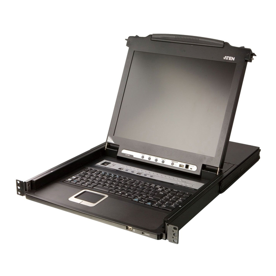
- Page 1 LCD KVM Switch CL5208 / CL5216 User Manual www.aten.com...
-
Page 2: Fcc Information
CL5208 / CL5216 User Manual FCC Information This is an FCC Class A product. In a domestic environment this product may cause radio interference in which case the user may be required to take adequate measures. This equipment has been tested and found to comply with the limits for a Class A digital device, pursuant to Part 15 of the FCC Rules. -
Page 3: User Information
CL5208 / CL5216 User Manual User Information Online Registration Be sure to register your product at our online support center: International http://support.aten.com North America http://www.aten-usa.com/product_registration Telephone Support For telephone support, call this number: International 886-2-8692-6959 China 86-10-5255-0110 Japan 81-3-5323-7178 Korea... -
Page 4: Package Contents
© Copyright 2009 ATEN® International Co., Ltd. Manual Part No. PAPE-0270-202G Manual Date: 2010-03-16 ATEN and the ATEN logo are registered trademarks of ATEN International Co., Ltd. All rights reserved. All other brand names and trademarks are the registered property of their respective owners. -
Page 5: Table Of Contents
Components ..........6 CL5208 / CL5216 Front View ....... . 6 CL5208C / CL5208D Rear View (DC Power) . - Page 6 CL5208 / CL5216 User Manual Powering Off and Restarting........22 LCD OSD Configuration .
- Page 7 CL5216 – ACS1208A ........
-
Page 8: About This Manual
CL5208 / CL5216. Chapter 4, OSD Operation, provides a complete description of the CL5208 / CL5216's OSD (on-screen display), and how to work with it. Chapter 5, Keyboard Port Operation, details all of the concepts and procedures involved in the Hotkey operation of your CL5208 / CL5216 installation. -
Page 9: Conventions
For information about all ATEN products and how they can help you connect without limits, visit ATEN on the Web or contact an ATEN Authorized Reseller. Visit ATEN on the Web for a list of locations and telephone numbers: International http://www.aten.com... - Page 10 CL5208 / CL5216 User Manual This Page Intentionally Left Blank...
-
Page 11: Introduction
(KVM) console. A single CL5208 or CL5216 can control up to 8 or 16 computers. As many as 31 additional KVM switches can be daisy chained to the CL5208 / CL5216, so that up to 512 computers can be controlled from a single KVM console. - Page 12 There is no better way to save time and money than with a CL5208 / CL5216 installation. By using the CL5208 / CL5216 with its sliding LCD console to manage your installation, you: (1) eliminate the expense of having to purchase a separate keyboard, monitor, and mouse for each computer;...
-
Page 13: Features
External console support – two console (one bus) access Daisy chain up to 31 additional units – control up to 504 (CL5208) or 512 (CL5216) computers CL5208C / CL5208D / CL5216C / CL5216D run on DC power No software required – convenient computer selection via Hotkeys and... -
Page 14: Requirements
CL5208 / CL5216 User Manual Requirements Computers The following equipment must be installed on each computer: A VGA, SVGA or multisync card. Note: The integrated LCD monitor's maximum resolution is 1024 x 768 @ 75 Hz (15") or 1280 x 1024 @ 75 Hz (17"). Make sure that none of the computer resolution settings exceed the LCD monitor's maximum resolution. -
Page 15: Os Support
1. Introduction OS Support Supported operating systems are shown in the table, below: Version Windows 2000 and higher Linux RedHat 7.1–7.3, 8.0, 9.0, Fedora Core 2–4 SuSE 8.2, 9.3, 10 Mandriva (Mandrake) 9, 2005 Limited Edition, 2006 UNIX AIX: 4.3, 5L FreeBSD 4.2, 4.5 Novell... -
Page 16: Components
CL5208 / CL5216 User Manual Components CL5208 / CL5216 Front View 5 & 6 11 & 12... - Page 17 Firmware Upgrade Port: The firmware upgrade cable that Upgrade transfers the firmware upgrade data from the Section administrator's computer to the CL5208 / CL5216 plugs into this RJ-11 connector. Firmware Upgrade Switch: During normal operation this switch should be in the NORMAL position.
-
Page 18: Cl5208C / Cl5208D Rear View (Dc Power)
4, for details). Do NOT attempt to use ordinary 15-pin VGA connector cables to link these ports to the computers. Ground The grounding wire used to ground the CL5208 / CL5216 attaches here. Power Switch This is a standard rocker switch that powers the CL5208 / CL5216 on and off. -
Page 19: Cl5208L / Cl5208M Rear View (Ac Power)
This is a standard rocker switch that powers the CL5208 / CL5216 on and off. External For flexibility and convenience, the CL5208 / CL5216 Console Section supports an independent, external, KVM console. The external console's keyboard, monitor, and mouse cables plug... - Page 20 CL5208 / CL5216 User Manual This Page Intentionally Left Blank...
-
Page 21: Hardware Setup
Keyboard Power On function. Standard Rack Mounting A standard rack mount kit is provided with your CL5208 / CL5216. The kit enables the switch to be mounted in rack with a depth of 42.0–82.0 cm. L Brackets... - Page 22 CL5208 / CL5216 User Manual To rack mount the switch, do the following: 1. While one person positions the switch in the rack and holds it in place, the second person loosely screws the front brackets to the rack. 2. While the first person still holds the switch in place, the second person...
-
Page 23: Single Stage Installation
DC Power Installation 1. Ground the unit. 2. If you choose to connect an external console to the CL5208 / CL5216, use the console cable provided to plug a keyboard, monitor, and mouse into the Console Port. - Page 24 CL5208 / CL5216 User Manual DC Power Installation Diagram...
-
Page 25: Ac Power Installation
2. Hardware Setup AC Power Installation 1. If you choose to connect an external console to the CL5208 / CL5216, use the console cable provided to plug a keyboard, monitor, and mouse into the Console Port. Note: Use of an external console is optional. -
Page 26: Daisy Chaining
To set up a daisy chained installation, first make sure that power to all the devices you will be connecting to the CL5208 / CL5216 have been turned off. Then, refer to the daisy chain installation diagram on the next page as you do the following: 1. - Page 27 2. Hardware Setup Daisy Chain Installation Diagram CL-5208 ACS-1216A ACS-1216A...
- Page 28 CL5208 / CL5216 User Manual This Page Intentionally Left Blank...
-
Page 29: Basic Operation
Basic Operation Opening the Console The CL5208 / CL5216's console is located under the top cover. To access the console, slide the console module out and raise the cover. Note: As a safety precaution, to keep the console from accidentally sliding out, the console is locked into the In position. -
Page 30: Closing The Console
CL5208 / CL5216 User Manual Closing the Console To slide the console module back in, close the cover and do the following: 1. Pull the safety catches on the unit's side rails toward you and push the module in until it stops. -
Page 31: Operating Precautions
3. Basic Operation Operating Precautions The maximum load bearing capacity of the keyboard module is 30kg. Failure to heed the information below can result in damage to the keyboard module. Right! Rest your hands and arms lightly on the keyboard module as you work. Wrong! DO NOT lean your body weight on the keyboard module. -
Page 32: Powering Up
Powering Up Power up the installation according to the following procedure: 1. Power on the first station (CL5208 / CL5216) and wait a few seconds for the unit to ascertain its station ID. 2. Plug in the power adapters for each daisy chained station on the installation in turn (second station, then third station, etc.). -
Page 33: Lcd Osd Configuration
3. Basic Operation LCD OSD Configuration The LCD Buttons The LCD OSD allows you to set up and configure the LCD display. Four buttons are used to perform the configuration, as described in the table, below: Button Function MENU When you have not entered the LCD OSD Menu function, pressing this button invokes the Menu function, and brings up the Main Menu. -
Page 34: Lcd Adjustment Settings
CL5208 / CL5216 User Manual LCD Adjustment Settings An explanation of the LCD OSD adjustment settings is given in the table below: Setting Explanation Brightness Adjusts the background black level of the screen image. Contrast Adjusts the foreground white level of the screen image. -
Page 35: Port Id Numbering
The Station Number is a two digit number which reflects the switch's position in the daisy chain sequence. Note: 1. The CL5208 / CL5216 has a station number of 01. The first daisy chained unit (ACS-1208A) has a station number of 02, etc. -
Page 36: Hot Plugging
CL5208 / CL5216 User Manual Hot Plugging The CL5208 / CL5216 supports hot plugging. Components can be removed and added back into the installation by unplugging their cables from the ports without the need to shut the unit down. In order for hot plugging to work... -
Page 37: Osd Operation
Chapter 4 OSD Operation OSD Overview The on-screen display (OSD) is a menu driven method to handle computer control and switching operations. All procedures start from the OSD Main Screen. To pop up the Main Screen, tap the OSD key (see page 69), or tap the [Scroll Lock] key twice. - Page 38 CL5208 / CL5216 User Manual When you invoke the OSD, a screen similar to the one below appears: F1:GOTO F3:SET F5:SKP F7:SCAN X F2:LIST F4:ADM F6:BRC F8:LOUT ADMINISTRATOR LIST:ALL SN PN NAME ATEN INTL.CO. 1 ATEN INTL.CO. 2 ATEN INTL.CO. 3...
-
Page 39: Osd Navigation
4. OSD Operation OSD Navigation To dismiss the menu, and deactivate the OSD, Click the X at the upper right corner of the OSD Window; or press [Esc]. To Logout, click F8 or the symbol at the top of the Main Screen, or press [F8]. -
Page 40: Osd Functions
CL5208 / CL5216 User Manual OSD Functions OSD functions are used to configure and control the OSD. For example, you can: rapidly switch to any port; scan selected ports only; limit the list you wish to view; designate a port as a Quick View Port; create or edit a port name; or make OSD setting adjustments. -
Page 41: F2: List
4. OSD Operation F2: LIST This function lets you broaden or narrow the scope of which ports the OSD displays on the Main Screen. Many of the OSD functions only operate on the computers currently selected for Listing on the Main Screen with this function. The submenu choices and their meanings are given in the table below: Choice Meaning... -
Page 42: F3: Set
CL5208 / CL5216 User Manual F3: SET This function allows the Administrator and each User to set up their own, individual, working environment. A separate profile for each is stored by the OSD and is activated according to the username provided during login. - Page 43 4. OSD Operation (Continued from previous page.) Setting Function PORT ID Selects how the Port ID is displayed: the Port Number alone DISPLAY (PORT NUMBER); the Port Name alone (PORT NAME); or the MODE Port Number plus the Port Name (PORT NUMBER + PORT NAME).
-
Page 44: F4: Adm
CL5208 / CL5216 User Manual F4: ADM F4 is an Administrator only function. It allows the Administrator to configure and control the overall operation of the OSD. To change a setting double-click it; or use the up and down arrow keys to move the highlight bar to it and then press [Enter]. - Page 45 4. OSD Operation (Continued from previous page.) Setting Function EDIT PORT To help remember which computer is attached to a particular port, NAMES every port can be given a name. This function allows the Administrator to create, modify, or delete port names. To Edit a port name: 1.
- Page 46 CL5208 / CL5216 User Manual (Continued from previous page.) Setting Function SET QUICK This function lets the Administrator select which Ports to include as VIEW PORTS Quick View ports. To select/deselect a port as a Quick View Port, use the Navigation Keys to move the highlight bar to it, then press the [Spacebar].
- Page 47 Set Quick View Ports, etc.), for all of the computers affected by the change, have to be manually redone. FIRMWARE In order to upgrade the CL5208 / CL5216's firmware (see UPGRADE Chapter 6), you must first enable Firmware Upgrade Mode with this setting.
-
Page 48: F5: Skp
CL5208 / CL5216 User Manual F5: SKP This function enables you to easily skip backward or forward, switching the KVM focus from the currently active computer port to the previous or next available one. The selection of computers available for Skip Mode switching is made with the Scan/Skip Mode setting under the F3 SET function (see p. -
Page 49: F6: Brc
4. OSD Operation F6: BRC F6 is an Administrator only function. When this function is in effect, commands sent from the console are broadcast to all available computers on the installation. This function is particularly useful for operations that need to be performed on multiple computers, such as performing a system wide shutdown, installing or upgrading software, etc. -
Page 50: F7: Scan
CL5208 / CL5216 User Manual F7: SCAN This function automatically switches among the available computers at regular intervals so that you can monitor their activity without having to take the trouble of switching manually. The selection of computers to be included for Auto Scanning is made with the Scan/Skip Mode setting under the F3 SET function (see p. -
Page 51: Keyboard Port Operation
Keyboard Port Operation Hotkey Port Access Hotkey port access allows you to provide the KVM focus to any computer on your installation directly from the keyboard. The CL5208 / CL5216 provides three hotkey port access features: Selecting the Active Port... -
Page 52: Selecting The Active Port
CL5208 / CL5216 User Manual Selecting the Active Port Each KVM port is assigned a unique port ID (see Port ID Numbering, page 25). You can directly access any computer on the installation with a hotkey combination that specifies the port ID of the KVM port that the computer is connected to. -
Page 53: Invoking Auto Scan
5. Keyboard Port Operation Invoking Auto Scan To start auto scanning, key in the following hotkey combination: 1. Invoke Hotkey mode (see p. 41). 2. Press [A]. When you press A, you automatically exit Hotkey mode; enter Auto Scan mode; and auto scanning begins. While you are in Auto Scan mode, you can pause the scanning in order to keep the focus on a particular computer either by pressing P or with a left click of the mouse. -
Page 54: Skip Mode
CL5208 / CL5216 User Manual Skip Mode This feature allows you to switch between computers in order to monitor them manually. You can dwell on a particular port for as long or as little as you like, as opposed to auto scanning, which automatically switches after a fixed interval. -
Page 55: Hotkey Beeper Control
5. Keyboard Port Operation Hotkey Beeper Control The Beeper can be hotkey toggled on and off (see ACTIVATE BEEPER, page 35). To toggle the beeper, key in the following hotkey combination: 1. Invoke Hotkey mode (see p. 41). 2. Press [B] After you press B, the beeper toggles on or off. - Page 56 CL5208 / CL5216 User Manual This Page Intentionally Left Blank...
-
Page 57: The Firmware Upgrade Utility
Chapter 6 The Firmware Upgrade Utility Overview The Windows-based firmware upgrade utility (FWUpgrade.exe) provides a smooth, automated process for upgrading the KVM switch's firmware. The utility comes as part of a firmware upgrade package that is specific for each device. New firmware upgrade packages are posted on our web site as new firmware revisions become available. -
Page 58: Preparation
CL5208 / CL5216 User Manual Preparation To prepare for the firmware upgrade, do the following: 1. From a computer that is not part of your KVM installation go to our Internet support site and choose the model name that relates to your device to get a list of available firmware upgrade packages. -
Page 59: Starting The Upgrade
6. The Firmware Upgrade Utility Starting the Upgrade To upgrade your firmware: 1. Run the downloaded firmware upgrade package file, either by double- clicking the file icon, or by opening a command line and entering the full path to it. The Firmware Upgrade Utility Welcome screen appears: Note: The screens shown in this section are for reference only. - Page 60 CL5208 / CL5216 User Manual The firmware upgrade utility main screen appears: The utility inspects your installation. The devices capable of being upgraded are listed in the Device List panel. 4. After all the devices have been listed, click Next to perform the upgrade.
-
Page 61: Upgrade Succeeded
6. The Firmware Upgrade Utility As the upgrade proceeds status messages appear in the Status Messages panel, and the progress toward completion is shown on the Progress bar. To abort the upgrade procedure before it completes, click Cancel. If you cancel before completion, a dialog box appears warning you that quitting at this point may cause the device’s firmware to be lost, and you are given the option to proceed or abort the cancel operation. -
Page 62: Firmware Upgrade Recovery
CL5208 / CL5216 User Manual Firmware Upgrade Recovery There are basically three conditions that call for firmware upgrade recovery: When you invoke Firmware Upgrade mode (see Preparation, page 48), but decide not to proceed with the upgrade. When the mainboard firmware upgrade fails. -
Page 63: Appendix
Appendix Safety Instructions General Read all of these instructions. Save them for future reference. Follow all warnings and instructions marked on the device. Do not place the device on any unstable surface (cart, stand, table, etc.). If the device falls, serious damage will result. Do not use the device near water. - Page 64 CL5208 / CL5216 User Manual If an extension cord is used with this device make sure that the total of the ampere ratings of all products used on this cord does not exceed the extension cord ampere rating. Make sure that the total of all products plugged into the wall outlet does not exceed 15 amperes.
-
Page 65: Rack Mounting
Appendix Rack Mounting Before working on the rack, make sure that the stabilizers are secured to the rack, extended to the floor, and that the full weight of the rack rests on the floor. Install front and side stabilizers on a single rack or front stabilizers for joined multiple racks before working on the rack. -
Page 66: Technical Support
CL5208 / CL5216 User Manual Technical Support International For online technical support – including troubleshooting, documentation, and software updates: http://support.aten.com For telephone support, see Telephone Support, page iii. North America Email Support ATEN TECH support@aten-usa.com ATEN NJ sales@aten.com Online Technical Support ATEN TECH http://www.aten-usa.com/support... -
Page 67: Specifications
Appendix Specifications Function CL5208C CL5208D Computer Direct Connections 256 (via 32-level daisy chain) Console Connections Port Selection OSD; Hotkey; Pushbutton Switches Connectors External Keyboard 1 x 6-pin Mini-DIN F (Purple) Console Ports Video 1 x HDB-15 F Mouse 1 x 6-pin Mini-DIN F (Green) KVM Ports 8 x SPHD-15 F Daisy Chain... - Page 68 CL5208 / CL5216 User Manual Function CL5208L CL5208M Computer Direct Connections 256 (via 32-level daisy chain) Console Connections Port Selection OSD; Hotkey; Pushbutton Switches Connectors External Keyboard 1 x 6-pin Mini-DIN F (Purple) Console Ports Video 1 x HDB-15 F...
- Page 69 Appendix Function CL5216C CL5216D Computer Direct Connections 512 (via 32-level daisy chain) Console Connections Port Selection OSD; Hotkey; Pushbutton Switches Connectors External Keyboard 1 x 6-pin Mini-DIN F (Purple) Console Ports Video 1 x HDB-15 F Mouse 1 x 6-pin Mini-DIN F (Green) KVM Ports 16 x SPHD-15 F Daisy Chain...
- Page 70 CL5208 / CL5216 User Manual Function CL5216L CL5216M Computer Direct Connections 512 (via 32-level daisy chain) Console Connections Port Selection OSD; Hotkey; Pushbutton Switches Connectors External Keyboard 1 x 6-pin Mini-DIN F (Purple) Console Ports Video 1 x HDB-15 F...
-
Page 71: Connection Tables
Appendix Connection Tables The following tables indicate the relationship between the number of units and the number of computers that they control on a daisy chained installation: CL5208 – ACS1208A Computers Computers Computers Computers 1–8 65–72 129–136 193–200 9–16 73–80 137–144 201–208 17–24... -
Page 72: Cl5216 - Acs1208A
CL5208 / CL5216 User Manual CL5216 – ACS1208A Computers Computers Computers Computers 1–16 73–80 137–144 201–208 17–24 81–88 145–152 209–216 25–32 89–96 153–160 217–224 33–40 97–104 161–168 225–232 41–48 105–112 169–176 233–240 49–56 113–120 177–184 241–248 57–64 121–128 185–192 249–256 65–72... -
Page 73: Clear Login Information
Appendix Clear Login Information If you are unable to perform an administrator login (because the username and password information has become corrupted, or you have forgotten it, for example), you can clear the login information with the following procedure: 1. Power off the switch and remove the top cover from the unit chassis. 2. -
Page 74: Osd Factory Default Settings
CL5208 / CL5216 User Manual OSD Factory Default Settings The factory default settings are as follows: Setting Default OSD Hotkey [Scroll Lock] [Scroll Lock] Port ID Display Position Upper Left Corner Port ID Display Duration 3 Seconds Port ID Display Mode... -
Page 75: Optional Rack Mounting
Appendix Optional Rack Mounting For convenience and flexibility, three optional rack mounting kits are available: A long bracket standard rack mounting kit for 68.0–110.0 cm racks; A short bracket Easy-Installation rack mount kit for 52.0–70.0 cm racks; A long bracket Easy-Installation rack mount kit for 68.0–105.0 cm racks. Standard –... - Page 76 CL5208 / CL5216 User Manual (Continued from previous page.) 2. Attach the left and right easy-installation mounting rails to the inside of the rack. The flange that supports the switch will be to the inside. Rear Flange Slide Bar Rear Attachment...
- Page 77 Appendix 3. Slide the switch onto the support flanges. Use the screws supplied with this package to loosely attach the front of the switch to the front of the rack (only tighten the screws part way). Phillips I head M4 x 6 4.
-
Page 78: Troubleshooting
There are ghost images on The distance between the external console and the the external monitor. CL5208 / CL5216 is too great. The maximum VGA cable distance should not exceed 20 m and, in some cases, may need to be shorter. Replace the VGA... -
Page 79: Dedicated Invocation Keys
Appendix Dedicated Invocation Keys Two dedicated keys are provided on the keyboard module to make it easy to invoke Hotkey Mode and the OSD, as shown in the diagram, below. Note: These keys are toggles. Press them once to invoke the feature, press them again to exit. - Page 80 CL5208 / CL5216 User Manual This Page Intentionally Left Blank...
- Page 81 Dedicated Invocation Keys, 69 Activate, 35 Hotkey Control, 45 BRC, 39 Easy installation rack mounting, 65 Broadcast Mode, 39 Edit Port Names, 35 CL5208 / CL5216 F1 GOTO, 30 Front View, 6 F2 LIST, 31 Overview, 1 F3 SET, 32 CL5208C / CL5208D...
- Page 82 CL5208 / CL5216 User Manual GOTO, 30 Online Registration, iii Opening the Console, 19 Hot Plugging, 26 Operating Precautions, 21 KVM Ports, 26 Optional rack mounting, 65 Hotkey Auto scanning, 42 Factory Default Settings, 64 Beeper Control, 45 Functions, 30...
- Page 83 Index Safety information, 55 USERNAME, 34 Standard, 11 Setting the Auto Scan Interval, 42 Rear View SJ/T 11364-2006, ii CL5208C / CL5208D, 8 Skip Mode, 33, 38, 44 CL5208L / CL5208M, 9 SKP, 38 CL5216C / CL5216D, 8 Specifications CL5216L / CL5216M, 9 CL5208C, 57 Requirements CL5208D, 57...
Need help?
Do you have a question about the CL5216 and is the answer not in the manual?
Questions and answers