Table of Contents
Advertisement
Quick Links
Advertisement
Table of Contents

Related Manuals for ATEN CL5800


Summary of Contents for ATEN CL5800
- Page 1 CL5800 LCD Console User Manual...
-
Page 2: Compliance Statements
CL5800 User Manual Compliance Statements FEDERAL COMMUNICATIONS COMMISSION INTERFERENCE STATEMENT This equipment has been tested and found to comply with the limits for a Class A digital device, pursuant to Part 15 of the FCC Rules. These limits are designed to provide reasonable protection against harmful interference when the equipment is operated in a commercial environment. - Page 3 CL5800 User Manual Industry Canada Statement This Class A digital apparatus complies with Canadian ICES-003. RoHS This product is RoHS compliant.
-
Page 4: About This Manual
CL5800 User Manual About this Manual This User Manual is provided to help you get the most from your CL5800 system. It covers all aspects of installation, configuration and operation. An overview of the information found in the manual is provided below. -
Page 5: Package Contents
CL5800 User Manual Package Contents The CL5800 package consists of: 1 CL5800 LCD Console with Standard Rack Mount Kit 1 custom KVM cable 1 power cord 1 firmware upgrade cable 1 user instructions* Check to make sure that all of the components are present and in good order. -
Page 6: Product Information
For information about all ATEN products and how they can help you connect without limits, visit ATEN on the Web or contact an ATEN Authorized Reseller. Visit ATEN on the Web for a list of locations and telephone numbers: International http://www.aten.com... -
Page 7: User Notice
CL5800 User Manual User Notice All information, documentation, and specifications contained in this manual are subject to change without prior notification by the manufacturer. The manufacturer makes no representations or warranties, either expressed or implied, with respect to the contents hereof and specifically disclaims any warranties as to merchantability or fitness for any particular purpose. -
Page 8: Table Of Contents
CL5800 User Manual Contents Compliance Statements ........ii About this Manual . - Page 9 CL5800 User Manual LCD OSD Configuration ........24 LCD Buttons .
- Page 10 CL5800 User Manual This Page Intentionally Left Blank...
-
Page 11: Chapter 1 Introduction
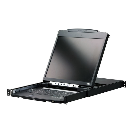
Chapter 1 Introduction Overview The CL5800 is a series of KVM Console modules featuring an integrated 19" LED-backlit LCD panel, a full keyboard, and a touch pad in a 1U rack- mountable sliding housing with an AC based input power source. -
Page 12: Features
Standard 105-key keyboard; Sun keyboard emulation Dual rail design allows LCD monitor and keyboard/touch pad modules to operate independently Compatible with all ATEN KVM Switches and most other KVM switches Adjustable depth to fit within the rack Firmware upgradeable ... -
Page 13: Requirements
Chapter 1. Introduction Requirements LCD Console The LCD console supports most KVM switches. If you are unsure whether your switch is supported or not, check with your dealer. The integrated LCD monitor's maximum resolution is 1280 x 1024 @75Hz. -
Page 14: Operating Systems
CL5800 User Manual Operating Systems Supported operating systems are shown in the table below. Version Windows NT or later Linux RedHat 7.1 or later SuSE 9.0 or later Mandriva (Mandrake) 9.0 or later UNIX 4.3 or later FreeBSD 4.2 or later... -
Page 15: Components
Chapter 1. Introduction Components Front View Component Description upper handle Pull to slide the LCD module out; push to slide the module in. See Opening the Console, page 17, for details on sliding the console in and out. LCD module See LCD Module, page 7. -
Page 16: Keyboard Module
reset button Pressing and holding this button while powering on the unit causes the CL5800 to revert to the original factory installed firmware version – allowing you to recover from a failed firmware upgrade. ... -
Page 17: Lcd Module
The firmware upgrade cable that transfers the firmware upgrade data from the administrator's computer to the upgrade port CL5800 plugs into this RJ-11 connector. firmware During normal operation and while performing a firmware upgrade, this switch should be in the NORMAL position. If... -
Page 18: Rear View
KVM console. The external console's keyboard, monitor, and mouse cables plug in here. KVM port section The cable linking the CL5800 to a computer or switch plugs in here. Note: The shape of this SPHD connector has been... -
Page 19: Chapter 2. Hardware Setup
You must unplug the power cords of any computers that have the Keyboard Power On function. 3. Packing material has been inserted to protect the CL5800 during shipping. Slide the LCD module out (see Opening the Console, page 17), until the packing material is visible. -
Page 20: Standard Rack Mounting
CL5800 User Manual Standard Rack Mounting A standard rack mount kit can be purchased separately for your CL5800. The kit enables the CL5800 to be mounted in rack with a depth of 52–85 cm. left & right L-shaped brackets side mount bracket Note: ... - Page 21 Chapter 2. Hardware Setup To rack mount the CL5800, do the following: 1. Have one person position the unit in the rack and hold it steady. Have the second person screw the front brackets to the rack. 2. While the first person still holds the unit in place, the second person slides the left &...
-
Page 22: Front-L Brackets Mounting
CL5800 User Manual Front-L Brackets Mounting To have a comfortable and safe posture, install the Front-L brackets which provide an extension at the front of the rack to help the unit slide further out and thus allowing you to tilt the LCD screen more. Instructions to use this option are shown below: 1. - Page 23 Chapter 2. Hardware Setup 3. While the first person still holds the unit in place, the second person slides the left & right L-shaped brackets into the unit’s side mounting brackets from the rear, installing four screws in the brackets to secure them in place. 4.
-
Page 24: Optional Rack Mount Kits
CL5800 User Manual Optional Rack Mount Kits For convenience and flexibility, optional rack mount kits are available and are listed in the table below: Mounting Kit Description Standard Long Rack Mount This kit is the long-railed version of your standard rack mount kit that lets you fit your device to racks with greater depth. -
Page 25: Connecting Up
LCD console. The ports are color coded and marked with an icon for easy identification. 4. Plug the CL5800’s power cord into the LCD Console’s power socket and into a power source. 5. Power up your KVM installation. - Page 26 CL5800 User Manual This Page Intentionally Left Blank...
-
Page 27: Chapter 3. Operation
Chapter 3 Operation Opening the Console The CL5800’s console consists of two modules: an LCD display module located under the top cover; and a keyboard / touch pad module below the LCD module. The modules can either slide together, or independently. This allows you to have the LCD display available for viewing while the keyboard / touch pad module is conveniently out of the way when not in use. - Page 28 CL5800 User Manual 3. Rotate the top panel all the way back to expose the LCD screen.
-
Page 29: Opening Together
Chapter 3. Operation 4. Reach underneath and pull the keyboard module all the way out until it clicks into place. Opening Together Refer to the diagrams in the Opening Separately section as you do the following: 1. Pull the release catch and pull the top and bottom panels out until the keyboard module clicks into place. -
Page 30: Operating Precautions
CL5800 User Manual Operating Precautions The maximum load bearing capacity of the keyboard module is 30kg. Failure to heed the information below can result in damage to the keyboard module. RIGHT Rest your hands and arms lightly on the keyboard module as you work. -
Page 31: Closing The Console
Chapter 3. Operation Closing the Console 1. Pull the release catches located on either side of the keyboard toward you to release the keyboard module, then slide the module slightly in. 2. Let go of the catches. Using the front handle, push the keyboard module all the way in. - Page 32 CL5800 User Manual 3. Rotate the LCD module all the way down, then pull the rear catches to release the LCD module. 4. Using the front handle, push the module all the way in.
-
Page 33: Hot Plugging
CL5800. Powering Off and Restarting If it becomes necessary to Power Off the CL5800 (to upgrade the firmware, for example), simply turn off the power to the unit using the rear panel power switch. To restart the CL5800, turn the rear panel power switch back on. -
Page 34: Lcd Osd Configuration
CL5800 User Manual LCD OSD Configuration LCD Buttons The LCD OSD allows you to set up and configure the LCD display. Four buttons are used to perform the configuration, as described in the table, below: Button Function MENU When you have not entered the LCD OSD Menu function, pressing this button invokes the Menu function, and brings up the Main Menu. -
Page 35: Lcd Adjustment Settings
Manufacturing Number The “MFG Number” (Manufacturing Number) is an internal serial number used by ATEN’s factory and technical support staff to identify products. This number does not affect products’ warranty. If your product requires after-sales services, you may provide the MFG Number to ATEN’s sales or technical... -
Page 36: Hotkeys
Note: 1. Press the keys in sequence – one key at a time. First [Ctrl], then [Alt], then [Shift], etc. 2. Console selections are not saved. If the CL5800 is powered off, it reverts to the default setting of both consoles enabled when it is powered on again. -
Page 37: Chapter 4. Firmware Upgrade
Before You Begin To prepare for the firmware upgrade, do the following: 1. From a computer that is not part of your CL5800 installation go to ATEN’s Internet support site and choose the model name that relates to your device to get a list of available Firmware Upgrade Packages. -
Page 38: Firmware Upgrade Mode
(see page 7) must be switched to the Normal position. 1. Turn off the CL5800 using the power switch on the back side of the console. 2. Slide the firmware switch to RECOVER (see page 7). -
Page 39: Performing The Upgrade
Performing the Upgrade Starting the Upgrade: 1. With the CL5800 in Firmware Upgrade Mode, run the downloaded Firmware Upgrade Package file from your computer - either by double clicking the file icon, or by opening a command line and keying in the full path and filename. - Page 40 CL5800 User Manual 3. Click Next. The Firmware Upgrade Utility main screen appears: The Utility inspects your installation. All the devices capable of being upgraded by the package are listed in the Device List panel. 4. Click Next to perform the upgrade.
-
Page 41: Upgrade Succeeded
Chapter 4. Firmware Upgrade Upgrade Succeeded When the upgrade completes, a success message will appear. An example is shown: Click Finish to close the Firmware Upgrade Utility. -
Page 42: Upgrade Failed
CL5800 User Manual Upgrade Failed If the firmware upgrade fails (Upgrade Succeeded screen does not appear), you can recover the situation. An upgrade failed message appears, an example is shown: Possible reasons for firmware upgrade failure are: When a firmware upgrade was manually aborted. -
Page 43: Exiting Firmware Upgrade Mode
To exit the Firmware Upgrade Mode, do the following: 1. Slide the firmware upgrade switch (see page 7) to the Normal position. 2. Power off and restart the CL5800 using the power switch on the back side of the console. - Page 44 CL5800 User Manual This Page Intentionally Left Blank...
-
Page 45: Appendix
Appendix Safety Instructions General This product is for indoor use only. Read all of these instructions. Save them for future reference. Follow all warnings and instructions marked on the device. Do not place the device on any unstable surface (cart, stand, table, etc.). If the device falls, serious damage will result. - Page 46 CL5800 User Manual If an extension cord is used with this device make sure that the total of the ampere ratings of all products used on this cord does not exceed the extension cord ampere rating. Make sure that the total of all products plugged into the wall outlet does not exceed 15 amperes.
-
Page 47: Rack Mounting
Appendix Rack Mounting Before working on the rack, make sure that the stabilizers are secured to the rack, extended to the floor, and that the full weight of the rack rests on the floor. Install front and side stabilizers on a single rack or front stabilizers for joined multiple racks before working on the rack. -
Page 48: Consignes De Sécurité
CL5800 User Manual Consignes de sécurité Général Ce produit est destiné exclusivement à une utilisation à l’intérieur. Veuillez lire la totalité de ces instructions. Conservez-les afin de pouvoir vous y référer ultérieurement. Respectez l’ensemble des avertissements et instructions inscrits sur l’appareil. - Page 49 Appendix L’équipement doit être installé à proximité de la prise murale et le dispositif de déconnexion (prise de courant femelle) doit être facile d’accès. La prise murale doit être installée à proximité de l’équipement et doit être facile d’accès. ...
- Page 50 CL5800 User Manual L’unité a été exposée à la pluie ou à l’eau. L’unité est tombée ou le boîtier a été endommagé. Les performances de l’unité sont visiblement altérées, ce qui indique la nécessité d’une réparation. L’unité ne fonctionne pas normalement bien que les instructions d’utilisation soient respectées.
-
Page 51: Montage Sur Bâti
Appendix Montage sur bâti Avant de travailler sur le bâti, assurez-vous que les stabilisateurs sont bien fixées sur le bâti, qu’ils sont étendus au sol et que tout le poids du bâti repose sur le sol. Installez les stabilisateurs avant et latéraux sur un même bâti ou bien les stabilisateurs avant si plusieurs bâtis sont réunis, avant de travailler sur le bâti. -
Page 52: Technical Support
CL5800 User Manual Technical Support International For online technical support – including troubleshooting, documentation, and software updates: http://eservice.aten.com For telephone support, see Telephone Support, page vi. North America Email Support support@aten-usa.com Online Troubleshooting http://www.aten-usa.com/support Technical Documentation Support Software Updates... -
Page 53: Specifications
Appendix Specifications Function CL5800 Computer Connections Console Selection Hotkey External Keyboard 1 x 6-pin Mini-DIN Female (Purple) Console Ports 1 x USB Type A Female (Black) Video 1 x HDB-15 Female (Blue) Connectors Mouse 1 x 6-pin Mini-DIN Female (Green) -
Page 54: About Sphd Connectors
CL5800 User Manual About SPHD Connectors This product uses SPHD connectors for its KVM and/or Console ports. We have specifically modified the shape of these connectors so that only KVM cables that we have designed to work with this product can be connected. -
Page 55: Sun Keyboard Emulation
Appendix Sun Keyboard Emulation The PC compatible (101/104 key) keyboard can emulate the functions of the Sun keyboard when the Control key [Ctrl] is used in conjunction with other keys. The corresponding functions are shown in the table below. PC Keyboard Sun Keyboard [Ctrl] [T] Stop... -
Page 56: Troubleshooting
There are ghost images on the The distance between the external console and the external monitor. CL5800 is too great. The maximum VGA cable distance should not exceed 20m and, in some cases, may need to be shorter. Replace the VGA cable with one of an appropriately short length. -
Page 57: Limited Warranty
© Copyright 2021 ATEN® International Co., Ltd. Released: 2021-05-12 ATEN and the ATEN logo are registered trademarks of ATEN International Co., Ltd. All rights reserved. All other brand names and trademarks are the registered property of their respective owners. - Page 58 CL5800 User Manual This Page Intentionally Left Blank...
- Page 59 Index OSD configuration, 24 AC Power Models Specifications, 43 Online Registration, vi Opening the Console, 17 CL5800 Operating Precautions, 20 Front View, 5 Keyboard Module, 6 LCD Module, 7 Port ID Rear View (AC Power), 8 Numbering & Selection, 23...
- Page 60 CL5800 User Manual User Notice, vii Warranty, 47...
Need help?
Do you have a question about the CL5800 and is the answer not in the manual?
Questions and answers