Table of Contents
Advertisement
Quick Links
Advertisement
Table of Contents

Related Manuals for ATEN CL5800


Summary of Contents for ATEN CL5800
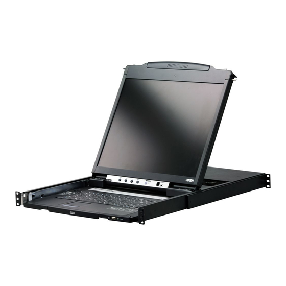
- Page 1 Dual Rail LCD PS/2 - USB Console CL5800 User Manual www.aten.com...
-
Page 2: Fcc Information
CL5800 User Manual FCC Information This is an FCC Class A product. In a domestic environment this product may cause radio interference in which case the user may be required to take adequate measures. This equipment has been tested and found to comply with the limits for a Class A digital device, pursuant to Part 15 of the FCC Rules. -
Page 3: User Information
CL5800 User Manual User Information Online Registration Be sure to register your product at our online support center: International http://support.aten.com North America http://www.aten-usa.com/product_registration Telephone Support For telephone support, call this number: International 886-2-8692-6959 China 86-10-5255-0110 Japan 81-3-5615-5811 Korea 82-2-467-6789 North America... -
Page 4: Package Contents
Manual Part No. PAPE-0313-AT2G F/W Version: 1.3.122 Manual Date: 2011-05-18 ATEN and the ATEN logo are registered trademarks of ATEN International Co., Ltd. All rights reserved. All other brand names and trademarks are the registered property of their respective owners. -
Page 5: Table Of Contents
CL5800 User Manual Contents FCC Information ..........ii RoHS. - Page 6 CL5800 User Manual The LCD Buttons......... 20 LCD Adjustment Settings .
-
Page 7: About This Manual
CL5800 User Manual About this Manual This User Manual is provided to help you get the most from your CL5800 system. It covers all aspects of installation, configuration and operation. An overview of the information found in the manual is provided below. -
Page 8: Conventions
For information about all ATEN products and how they can help you connect without limits, visit ATEN on the Web or contact an ATEN Authorized Reseller. Visit ATEN on the Web for a list of locations and telephone numbers: International http://www.aten.com... -
Page 9: Chapter 1 Introduction
Chapter 1 Introduction Overview The CL5800 is a series of KVM Console modules featuring an integrated 19" LCD panel, a full keyboard, and a touch pad in a 1U rack-mountable sliding housing with an AC based input power source. The CL5800 KVM Console modules serve as the front end sliding console for compatible KVM switches. -
Page 10: Features
Standard 105-key keyboard; Sun keyboard emulation Dual rail design allows LCD monitor and keyboard/touch pad modules to operate independently Compatible with all ATEN KVM Switches and most other KVM switches Adjustable depth to fit within the rack Firmware upgradeable Supports Microsoft Intellimouse (5 keys) Supports Logitech and Microsoft wireless mice Console lock –... -
Page 11: Requirements
Chapter 1. Introduction Requirements LCD Console The LCD console supports most KVM switches. If you are unsure whether your switch is supported or not, check with your dealer. The integrated LCD monitor's maximum resolution is 1280 x 1024 @75Hz. Make sure that none of the resolution settings of the connected computers exceed the LCD monitor's maximum resolution. -
Page 12: Operating Systems
CL5800 User Manual Operating Systems Supported operating systems are shown in the table, below. Version Windows NT and higher Linux RedHat 7.1 and higher SuSE 9.0 and higher Mandriva (Mandrake) 9.0 and higher UNIX 4.3 and higher FreeBSD 4.2 and higher... -
Page 13: Components
Chapter 1. Introduction Components Front View Component Description Upper Handle Pull to slide the LCD module out; push to slide the module in. See Opening the Console, page 13, for details on sliding the console in and out. LCD Module See LCD Module, page 7. -
Page 14: Keyboard Module
Reset Button Pressing and holding this button while powering on the unit causes the CL5800 to revert to the original factory installed firmware version – allowing you to recover from a failed firmware upgrade. -
Page 15: Lcd Module
The Firmware Upgrade Cable that transfers the firmware upgrade data from the administrator's computer to the Upgrade Port CL5800 plugs into this RJ-11 connector. Firmware During normal operation and while performing a firmware upgrade, this switch should be in the NORMAL position. If a... -
Page 16: Rear View
KVM console. The external console's keyboard, monitor, and mouse cables plug in here. KVM Port The cable linking the CL5800 to a computer or switch plugs in Section here. Note: The shape of this SPHD connector has been... -
Page 17: Chapter 2. Hardware Setup
You must unplug the power cords of any computers that have the Keyboard Power On function. 3. Packing material has been inserted to protect the CL5800 during shipping. Slide the LCD module out (see Opening the Console, page 13), until the packing material is visible. -
Page 18: Standard Rack Mounting
CL5800 User Manual Standard Rack Mounting A standard rack mounting kit can be purchased separately for your CL5800. The kit enables the CL5800 to be mounted in rack with a depth of 52–85 cm. L Brackets Side Mountng Brackets Note: 1. It takes two people to mount the switch: one to hold it in place, the other to screw it in. - Page 19 Chapter 2. Hardware Setup To rack mount the CL5800, do the following: 1. While one person positions the CL5800 in the rack and holds it in place, the second person loosely screws the front brackets to the rack. 2. While the first person still holds the CL5800 in place, the second person...
-
Page 20: Connecting Up
Console Section of the LCD Console. The ports are color coded and marked with an icon for easy identification. 4. Plug the CL5800’s power cord into the LCD Console's power socket and into a power source. 5. Power up your KVM installation. -
Page 21: Chapter 3. Operation
Chapter 3 Operation Opening the Console The CL5800's console consists of two modules: an LCD display module located under the top cover; and a keyboard / touch pad module below the LCD module. The modules can either slide together, or independently. This allows you to have the LCD display available for viewing while the keyboard / touch pad module is conveniently out of the way when not in use. - Page 22 CL5800 User Manual 2. Pull the top panel all the way out until it clicks into place. 3. Rotate the top panel all the way back to expose the LCD screen.
-
Page 23: Opening Together
Chapter 3. Operation 4. Reach underneath and pull the keyboard module all the way out until it clicks into place. Opening Together Refer to the diagrams in the Opening Separately section as you do the following: 1. Pull the release catch and pull the top and bottom panels out until the keyboard module clicks into place. -
Page 24: Operating Precautions
CL5800 User Manual Operating Precautions The maximum load bearing capacity of the keyboard module is 30kg. Failure to heed the information below can result in damage to the keyboard module. RIGHT Rest your hands and arms lightly on the keyboard module as you work. -
Page 25: Closing The Console
Chapter 3. Operation Closing the Console 1. Pull the release catches located on either side of the keyboard toward you to release the keyboard module, then slide the module slightly in. 2. Let go of the catches. Using the front handle, push the keyboard module all the way in. - Page 26 CL5800 User Manual 3. Rotate the LCD module all the way down, then pull the rear catches to release the LCD module. 4. Using the front handle, push the module all the way in.
-
Page 27: Hot Plugging
CL5800. Powering Off and Restarting If it becomes necessary to Power Off the CL5800 (to upgrade the firmware, for example), simply turn off the power to the unit using the rear panel power switch. To restart the CL5800, turn the rear panel power switch back on. -
Page 28: Lcd Osd Configuration
CL5800 User Manual LCD OSD Configuration The LCD Buttons The LCD OSD allows you to set up and configure the LCD display. Four buttons are used to perform the configuration, as described in the table, below: Button Function MENU When you have not entered the LCD OSD Menu function, pressing this button invokes the Menu function, and brings up the Main Menu. -
Page 29: Lcd Adjustment Settings
Chapter 3. Operation LCD Adjustment Settings An explanation of the LCD OSD adjustment settings is given in the table below: Setting Explanation Brightness Adjusts the background black level of the screen image. Contrast Adjusts the foreground white level of the screen image. Phase If pixel jitter or horizontal line noise is visible on the display, your LCD may have the wrong phase setting. -
Page 30: Hotkeys
Note: 1. Press the keys in sequence – one key at a time. First [Ctrl], then [Alt], then [Shift], etc. 2. Console selections are not saved. If the CL5800 is powered off, it reverts to the default setting of both consoles enabled when it is powered on again. -
Page 31: Chapter 4. Firmware Upgrade
Before You Begin To prepare for the firmware upgrade, do the following: 1. From a computer that is not part of your CL5800 installation go to ATEN’s Internet support site and choose the model name that relates to your device to get a list of available Firmware Upgrade Packages. -
Page 32: Firmware Upgrade Mode
Firmware Upgrade Recovery Switch (see page 7) must be set to the Normal position. 1. Turn off the power to the CL5800 using the power switch located on the back side of the console. 2. Slide the firmware switch to RECOVER (see page 7). -
Page 33: Performing The Upgrade
Performing the Upgrade Starting the Upgrade: 1. With the CL5800 in Firmware Upgrade Mode, run the downloaded Firmware Upgrade Package file from your computer - either by double clicking the file icon, or by opening a command line and keying in the full path and filename. - Page 34 CL5800 User Manual (Continued from previous page.) 3. Click Next. The Firmware Upgrade Utility main screen appears: The Utility inspects your installation. All the devices capable of being upgraded by the package are listed in the Device List panel. 4. Click Next to perform the upgrade.
-
Page 35: Upgrade Succeeded
Chapter 4. Firmware Upgrade Upgrade Succeeded: After the upgrade has completed, a screen appears to inform you that the procedure was successful: Click Finish to close the Firmware Upgrade Utility. -
Page 36: Upgrade Failed
CL5800 User Manual Upgrade Failed: If the upgrade failed to complete successfully the Upgrade Failed screen appears: Click Cancel to close the Firmware Upgrade Utility. See the next section, Firmware Upgrade Recovery, for how to proceed. -
Page 37: Firmware Upgrade Recovery
To exit the Firmware Upgrade Mode, do the following: 1. Slide the Firmware Upgrade Recovery Switch (see page 7) to the Normal position. 2. Power off and restart the CL5800 according to the instructions given in the Powering Off and Restarting section (see page 19). - Page 38 CL5800 User Manual This Page Intentionally Left Blank...
-
Page 39: Appendix
Appendix Safety Instructions General Read all of these instructions. Save them for future reference. Follow all warnings and instructions marked on the device. Do not place the device on any unstable surface (cart, stand, table, etc.). If the device falls, serious damage will result. Do not use the device near water. - Page 40 CL5800 User Manual (Continued from previous page.) If an extension cord is used with this device make sure that the total of the ampere ratings of all products used on this cord does not exceed the extension cord ampere rating. Make sure that the total of all products plugged into the wall outlet does not exceed 15 amperes.
-
Page 41: Rack Mounting
Appendix Rack Mounting Before working on the rack, make sure that the stabilizers are secured to the rack, extended to the floor, and that the full weight of the rack rests on the floor. Install front and side stabilizers on a single rack or front stabilizers for joined multiple racks before working on the rack. -
Page 42: Technical Support
CL5800 User Manual Technical Support International For online technical support – including troubleshooting, documentation, and software updates: http://support.aten.com For telephone support, see Telephone Support, page iii. North America Email Support support@aten-usa.com Online Troubleshooting http://www.aten-usa.com/support Technical Documentation Support Software Updates Telephone Support... -
Page 43: Specifications
Appendix Specifications Function 19” LCD Computer Connections Console Selection Hotkey External Keyboard 1 x 6-pin Mini-DIN Female (Purple) Console Ports 1 x USB Type A Female (Black) Video 1 x HDB-15 Female (Blue) Connectors Mouse 1 x 6-pin Mini-DIN Female (Green) 1 x USB Type A Female (Black) KVM Ports 1 x SPHD-18 Female (Yellow) -
Page 44: Optional Rack Mounting
10. While it takes two people to perform a standard installation, with an Easy- Installation, kit, one person can mount the CL5800. To install the Easy- Installation kit, do the following: 1. Remove the standard sliding L brackets (not shown) and the side mounting brackets from both sides of the CL5800. - Page 45 Appendix 2. Attach the left and right easy-installation mounting rails to the inside of the rack. The flange that supports the CL5800 will be to the inside. Rear Flange Slide Bar Front Flange Rear Attachment Sliding Bracket LEFT Support RAIL...
- Page 46 CL5800 User Manual 3. Slide the CL5800 onto the support flanges. Use the screws supplied with this package to loosely attach the front of the CL5800 to the front of the rack (only tighten the screws part way). Phillips I head M4L6 4.
-
Page 47: About Sphd Connectors
Appendix 5. Slide the CL5800 open and closed a couple of times to be sure that it is properly aligned and operating smoothly. (See Opening the Console, page 13, for opening and closing procedures.) 6. After determining that the CL5800 is lined up and operating correctly, finish by fully tightening the front attachment screws inserted in Step 3. -
Page 48: Sun Keyboard Emulation
CL5800 User Manual Sun Keyboard Emulation The PC compatible (101/104 key) keyboard can emulate the functions of the Sun keyboard when the Control key [Ctrl] is used in conjunction with other keys. The corresponding functions are shown in the table below. -
Page 49: Troubleshooting
There are ghost images on the The distance between the external console and the external monitor. CL5800 is too great. The maximum VGA cable distance should not exceed 20m and, in some cases, may need to be shorter. Replace the VGA cable with one of an appropriately short length. -
Page 50: Limited Warranty
CL5800 User Manual Limited Warranty ATEN warrants this product against defects in material or workmanship for a period of one (1) year from the date of purchase. If this product proves to be defective, contact ATEN's support department for repair or replacement of your unit. ATEN will not issue a refund. Return requests can not be processed without the original proof of purchase. - Page 51 Index OSD configuration, 20 AC Power Models Specifications, 35 Online Registration, iii Opening the Console, 13 CL5800 Operating Precautions, 16 Front View, 5 Keyboard Module, 6 LCD Module, 7 Port ID Rear View (AC Power), 8 Numbering & Selection, 19...
- Page 52 CL5800 User Manual Troubleshooting, 41 Warranty, 42 User Notice, iii...
Need help?
Do you have a question about the CL5800 and is the answer not in the manual?
Questions and answers