Table of Contents
Advertisement
Advertisement
Table of Contents

Subscribe to Our Youtube Channel
Related Manuals for ATEN Slideaway CL1000


Summary of Contents for ATEN Slideaway CL1000
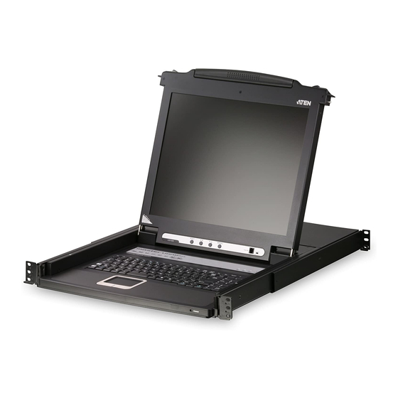
- Page 1 Slideaway LCD Console CL1000 User Manual www.aten.com...
-
Page 2: Fcc Information
CL1000 User Manual FCC Information This is an FCC Class A product. In a domestic environment this product may cause radio interference in which case the user may be required to take adequate measures. This equipment has been tested and found to comply with the limits for a Class A digital device, pursuant to Part 15 of the FCC Rules. -
Page 3: User Information
CL1000 User Manual User Information Online Registration Be sure to register your product at our online support center: International http://support.aten.com North America http://www.aten-usa.com/product_registration Telephone Support For telephone support, call this number: International 886-2-8692-6959 China 86-10-5255-0110 Japan 81-3-5615-5811 Korea 82-2-467-6789 North America... -
Page 4: User Notice
CL1000 User Manual User Notice All information, documentation, and specifications contained in this manual are subject to change without prior notification by the manufacturer. The manufacturer makes no representations or warranties, either expressed or implied, with respect to the contents hereof and specifically disclaims any warranties as to merchantability or fitness for any particular purpose. -
Page 5: Package Contents
© Copyright 2008–2011 ATEN® International Co., Ltd. Manual Part No. PAPE-0287-102G Manual Date: 2011-05-16 ATEN and the ATEN logo are registered trademarks of ATEN International Co., Ltd. All rights reserved. All other brand names and trademarks are the registered property of their respective owners. -
Page 6: Table Of Contents
CL1000 User Manual Contents FCC Information ..........ii RoHS . - Page 7 CL1000 User Manual Appendix Safety Instructions......... . . 17 General .
-
Page 8: About This Manual
CL1000 User Manual About this Manual This User Manual is provided to help you get the most from your CL1000 system. It covers all aspects of installation, configuration and operation. An overview of the information found in the manual is provided below. -
Page 9: Conventions
For information about all ATEN products and how they can help you connect without limits, visit ATEN on the Web or contact an ATEN Authorized Reseller. Visit ATEN on the Web for a list of locations and telephone numbers: International http://www.aten.com... - Page 10 CL1000 User Manual This Page Intentionally Left Blank...
-
Page 11: Introduction
Setup is fast and easy. Simply use the KVM cable set supplied with this package to link the CL1000's KVM port to the console port of your KVM switch and you are ready to go. 1. The CL1000 supports most KVM switches that have PS/2 console port connectors. If... -
Page 12: Features
CL1000 User Manual Features Integrated KVM console with a 17" LCD monitor in a sliding housing with top and bottom clearance for smooth operation in a 1U high system rack LCD module rotates up to 115 for a more comfortable viewing angle Standard rack mount kit included –... -
Page 13: Requirements
Chapter 1. Introduction Requirements Switches and Computers The CL1000 supports most KVM switches that have PS/2 console port connectors. If you are unsure whether your switch is supported or not, check with your dealer. The integrated LCD monitor's maximum resolution is 1280 x 1024 @ 75 Hz. -
Page 14: Components
CL1000 User Manual Components Front View No. Component Description Handle Pull to slide the KVM module out; push to slide the module in. Slide Release In order to slide the console out, you must first release it by moving this tab sideways. See page 11 for details on sliding the console in and out. -
Page 15: Rear View
This is a standard rocker switch that powers the unit On and Off. KVM Port The cable that links the CL1000 to the KVM switch plugs in here. Note: The shape of this SPHD connector has been specifically modified so that only KVM cables designed to work with this switch can plug in (see Cables, page 3, for details). - Page 16 CL1000 User Manual This Page Intentionally Left Blank...
-
Page 17: Hardware Setup
You must unplug the power cords of any computers that have the Keyboard Power On function. Standard Rack Mounting A standard rack mount kit is provided with your CL1000. The kit enables the console to be mounted in rack with a depth of 42–72 cm. L Brackets... - Page 18 CL1000 User Manual To rack mount the console, do the following: 1. While one person positions the CL1000 in the rack and holds it in place, the second person loosely screws the front brackets to the rack. 2. While the first person still holds the CL1000 in place, the second person...
-
Page 19: Installation
2. Plug the keyboard, monitor, and mouse connectors of the KVM cable into their respective ports on the Console Section of the KVM switch. 3. Plug the power cord into the CL1000's power socket and into an AC power source. - Page 20 CL1000 User Manual This Page Intentionally Left Blank...
-
Page 21: Operation
Chapter 3 Operation Opening the Console The CL1000's console is located under the top cover. To access the console, slide the console module out and raise the cover. Note: As a safety precaution, to keep the console from accidentally sliding out, the console is locked into the In position. -
Page 22: Closing The Console
CL1000 User Manual Closing the Console To slide the console module back in, close the cover and do the following: 1. Pull the safety catches on the unit's side rails toward you and push the module in until it stops. -
Page 23: Operating Precautions
Chapter 3. Operation Operating Precautions The maximum load bearing capacity of the keyboard module is 30 kg. Failure to heed the information below can result in damage to the keyboard module. Right! Rest your hands and arms lightly on the keyboard module as you work. -
Page 24: Lcd Osd Configuration
CL1000 User Manual LCD OSD Configuration The LCD Buttons The LCD OSD allows you to set up and configure the LCD display. Four buttons are used to perform the configuration, as described in the table, below: Button Function MENU When you have not entered the LCD OSD Menu function, pressing this button invokes the Menu function, and brings up the Main Menu. -
Page 25: The Adjustment Settings
Port ID Numbering & Port Selection Port ID numbering and Port Selection follow the method used by the KVM switch connected to the CL1000. Consult your KVM switch's User Manual for details. - Page 26 CL1000 User Manual This Page Intentionally Left Blank...
-
Page 27: Appendix
Appendix Safety Instructions General Read all of these instructions. Save them for future reference. Follow all warnings and instructions marked on the device. To prevent damage to your installation it is important that all devices are properly grounded. Do not place the device on any unstable surface (cart, stand, table, etc.). If the device falls, serious damage will result. - Page 28 CL1000 User Manual (Continued from previous page.) If an extension cord is used with this device make sure that the total of the ampere ratings of all products used on this cord does not exceed the extension cord ampere rating. Make sure that the total of all products plugged into the wall outlet does not exceed 15 amperes.
-
Page 29: Rack Mounting
Appendix Rack Mounting Before working on the rack, make sure that the stabilizers are secured to the rack, extended to the floor, and that the full weight of the rack rests on the floor. Install front and side stabilizers on a single rack or front stabilizers for joined multiple racks before working on the rack. -
Page 30: Technical Support
CL1000 User Manual Technical Support International For online technical support – including troubleshooting, documentation, and software updates: http://support.aten.com For telephone support, see page iii. North America Email Support support@aten-usa.com Online Troubleshooting http://www.aten-usa.com/support Technical Documentation Support Software Updates Telephone Support 1-888-999-ATEN ext 4988 When you contact us, please have the following information ready beforehand: Product model number, serial number, and date of purchase. -
Page 31: Specifications
Appendix Specifications Function CL1000 Connector KVM Ports 1 x SPHD-15 Female (Yellow) Switches Power 1 x Rocker LCD Adjust 4 x Pushbutton Reset 1 x Semi-recessed Pushbutton LEDs Power 1 (Dark Green) Lock 1 (Green) Caps 1 (Green) Scroll 1 (Green) -
Page 32: Optional Rack Mounting
CL1000 User Manual Optional Rack Mounting For convenience and flexibility, three optional rack mounting kits are available as shown in the following table: Bracket Type Size (cm) Standard Installation – Long 68.0–100.0 Easy Installation – Short 42.0–70.0 Easy Installation – Long 68.0–105.0... - Page 33 Appendix 2. Attach the left and right easy-installation mounting rails to the inside of the rack. The flange that supports the console will be to the inside. Rear Flange Slide Bar Sliding Attachment Bracket LEFT Support Rear Flange RAIL Flange RIGHT RAIL a) Screw the front flanges to the rack first.
- Page 34 CL1000 User Manual (Continued from previous page.) 3. Slide the console onto the support flanges. Use the screws supplied with this package to loosely attach the front of the console to the front of the rack (only tighten the screws part way).
-
Page 35: About Sphd Connectors
Appendix 5. Slide the console open and closed a couple of times to be sure that it is properly aligned and operating smoothly. (See page 11 for opening and closing procedures.) 6. After determining that the console is properly lined up and operating correctly, finish up by fully tightening down the partially tightened front attachment screws inserted in step 3. -
Page 36: Limited Warranty
CL1000 User Manual Limited Warranty IN NO EVENT SHALL THE DIRECT VENDOR'S LIABILITY EXCEED THE PRICE PAID FOR THE PRODUCT FROM DIRECT, INDIRECT, SPECIAL, INCIDENTAL, OR CONSEQUENTIAL DAMAGES RESULTING FROM THE USE OF THE PRODUCT, DISK, OR ITS DOCUMENTATION. The direct vendor makes no warranty or representation, expressed, implied, or statutory with respect to the contents or use of this documentation, and especially disclaims its quality, performance, merchantability, or fitness for any particular purpose. - Page 37 Index Operating Precautions, 13 Operating Temp., 21 Cables, 3 Optional rack mounting, 22 Components Front View, 4 Rear View, 5 Package Contents Conventions, ix Basic, v Optional Equipment, v Port ID Dimensions, 21 Numbering, 15 Power Consumption, 21 Power Socket, 5 Easy-Installation kit, 22 Power Switch, 5 Emulation...
- Page 38 CL1000 User Manual SPHD Connectors, 25 Standard rack mounting, 7 Storage Temp., 21 Technical Support, 20 Telephone support, iii Temperature operating, 21 storage, 21 User Notice, iv video resolution, 2 Warranty, 26 Weight, 21...
Need help?
Do you have a question about the Slideaway CL1000 and is the answer not in the manual?
Questions and answers