
Related Manuals for Beckhoff EJ7211-0010


Summary of Contents for Beckhoff EJ7211-0010
- Page 1 Documentation EJ7211-0010 Servomotor module for OCT, 48 V DC, 4.5 A (Irms) Version: Date: 2020-06-26...
-
Page 3: Table Of Contents
6 Commissionin ............................ 38 Note to EL7211-0010 documentation .................... 38 7 Diagnostics – basic principles of diag messages ................ 39 8 Appendix .............................. 49 EtherCAT AL Status Codes ...................... 49 EJ7211-0010 - Firmware compatibility .................... 49 Firmware Update EL/ES/EM/ELM/EPxxxx .................. 49 8.3.1 Device description ESI file/XML.................. 50 8.3.2 Firmware explanation ...................... - Page 4 Table of contents 8.3.3 Updating controller firmware *.efw................... 54 8.3.4 FPGA firmware *.rbf...................... 56 8.3.5 Simultaneous updating of several EtherCAT devices............ 60 Restoring the delivery state ...................... 61 Support and Service ........................ 62 Version: 1.0 EJ7211-0010...
-
Page 5: Foreword
EP1590927, EP1789857, EP1456722, EP2137893, DE102015105702 with corresponding applications or registrations in various other countries. ® EtherCAT is registered trademark and patented technology, licensed by Beckhoff Automation GmbH, Germany. Copyright © Beckhoff Automation GmbH & Co. KG, Germany. The reproduction, distribution and utilization of this document as well as the communication of its contents to others without express authorization are prohibited. -
Page 6: Safety Instructions
All the components are supplied in particular hardware and software configurations appropriate for the application. Modifications to hardware or software configurations other than those described in the documentation are not permitted, and nullify the liability of Beckhoff Automation GmbH & Co. KG. Personnel qualification This description is only intended for trained specialists in control, automation and drive engineering who are familiar with the applicable national standards. -
Page 7: Intended Use
Caution - Risk of injury! EJ components may only be used for the purposes described below! Documentation issue status Version Comment • First publication of EJ7211-0010 Guide through documentation NOTE Further components of documentation The documentations named in the following table are further compontents of the complete documentation. -
Page 8: Marking Of Ethercat Plug-In Modules
Foreword Marking of EtherCAT plug-in modules Designation A Beckhoff EtherCAT device has a 14-digit technical designation, made up as follows (e.g. EJ1008-0000-0017) • Order identifier ◦ family key: EJ ◦ product designation: The first digit of product designation is used for assignment to a product group (e.g. -
Page 9: Fig. 2 Order Identifier (A), Revision Number (B) And Serial Number (C) Using The Example Of Ej1008
Associated and synonymous with each revision there is usually a description (ESI, EtherCAT Slave Information) in the form of an XML file, which is available for download from the Beckhoff web site. • The product designation, version and revision are read as decimal numbers, even if they are technically saved in hexadecimal. -
Page 10: Beckhoff Identification Code (Bic)
1.6.1 Beckhoff Identification Code (BIC) The Beckhoff Identification Code (BIC) is increasingly being applied to Beckhoff products to uniquely identify the product. The BIC is represented as a Data Matrix Code (DMC, code scheme ECC200), the content is based on the ANSI standard MH10.8.2-2016. - Page 11 Example of composite information from items 1 - 4 and 6. The data identifiers are marked in red for better display: An important component of the BIC is the Beckhoff Traceability Number (BTN, item no. 2). The BTN is a unique serial number consisting of eight characters that will replace all other serial number systems at Beckhoff in the long term (e.g.
-
Page 12: Certificates
Canadian regulations. • The warning symbol is a request to read the corresponding documentation. The documentations for EtherCAT plug-in modules can be downloaded from the Beckhoff homepage. Fig. 4: Marking for CE and UL using EJ1008 as an example Version: 1.0... -
Page 13: System Overview
Coded components reduce the unit costs and the risk of miswiring. Beckhoff offers development of signal distribution boards as an engineering service. Customers have the option to develop their own signal distribution board, based on the design guide. -
Page 14: Product Overview
Servomotor module with OCT, 48 V , 4,5 A (I The servomotor EtherCAT plug-in module EJ7211-0010 with integrated One Cable Technology (OCT) offers high servo performance in a very compact design for the motor types of the AM8100 series, up to 4,5 A (I The One Cable Technology combines a motor cable and an absolute feedback system in a single cable. -
Page 15: Ej7211-0010 - Technical Data
Product Overview EJ7211-0010 - Technical data Technical data EJ7211-0010 Number of outputs 1 x servomotor, absolute Feedback, motor brake, 2 digital inputls Connection method Direct motor connection Load type Permanent-magnet synchronous motors DC link supply voltage 8...48 V Output current I 4.5 A (rms) / 6.3 A (peak value) -
Page 16: Technology
The EtherCAT servomotor module offers users the option to configure compact and cost-effective systems without having to give up the benefits of a servomotor. The Beckhoff servo module The EJ72x1-xxxx is a fully capable servo drive for direct connection to servomotors in the lower performance range. - Page 17 AC and DC motors. With the EJ72x1-xxxx servo module, the range of servo drives becomes even more finely scalable: from the miniature servo drive up to 170 W in the EtherCAT plug-in module through to the AX5000 servo drive with 118 kW, Beckhoff offers a wide range including the servomotors.
-
Page 18: Fig. 8 Limitation To The Rated Motor Current
Product Overview Fig. 8: Limitation to the rated motor current Version: 1.0 EJ7211-0010... -
Page 19: Ej7211-0010- Pinout
Product Overview EJ7211-0010- Pinout Fig. 9: EJ7211-0010 - Pinout The PCB footprint can be downloaded from the Beckhoff homepage. NOTE Damage to devices possible! • The pins named with “NC” must not be connected. • Before installation and commissioning read the chapters Installation of EJ modules [} 21] and Commissioning! -
Page 20: Ej7211-0010 - Leds
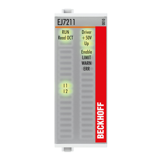
Product Overview EJ7211-0010 - LEDs Fig. 10: EJ7211-0010 - LEDs LEDs (left prism) Color Display State Meaning green Init State of the EtherCAT State Machine: INIT = Initialization of the terminal or BOOT- STRAP = Function for firmware updates of the terminal... -
Page 21: Installation Of Ej Modules
In the EJ1101-0022 coupler, the RJ45 connectors and optional ID switches are external and can be positioned anywhere on the signal distribution board, as required. This facilitates feeding through a housing. The EJ940x power supply plug-in modules provide an optional reset function (see chapter Connection of the documentation for EJ9400 and EJ9404) EJ7211-0010 Version: 1.0... -
Page 22: Fig. 12 Pcb With Embedded Pc, Ek1110-0043 And Ejxxxx, Rear View Ek1110-0043
The EK1110-004x EtherCAT EJ couplers relay the following parameters to the signal distribution board via the rear connector: • the E-bus signals, • the E-bus voltage U (3.3 V) and EBUS • the peripheral voltage U (24 V Fig. 12: PCB with Embedded PC, EK1110-0043 and EJxxxx, rear view EK1110-0043 Version: 1.0 EJ7211-0010... -
Page 23: Ejxxxx - Dimensions
12 mm x 152 mm x 55 mm EJ1957 (ej_12_2x16pin_extended_code4747) Fig. 13: EJxxxx - Dimensions The technical drawings can be downloaded from the download finder. The drawings are named as described in the drawing below. Fig. 14: Technical drawings from download finder EJ7211-0010 Version: 1.0... -
Page 24: Installation Positions And Minimum Distances
[} 25]) ensures an adequate reaching area. The signal distribution board must have a thickness of 1.6 mm and a minimum distance of 4 mm from the mounting surface, in order to ensure latching of the modules on the board. Version: 1.0 EJ7211-0010... -
Page 25: Installation Positions
The recommended minimum distances should not be regarded as restricted areas for other components. The customer is responsible for verifying compliance with the environmental conditions described in the technical data. Additional cooling measures must be provided, if required. EJ7211-0010 Version: 1.0... -
Page 26: Fig. 17 Other Installation Positions
All other installation positions are characterized by a different spatial position of the signal distribution board, see Fig. Other installation positions. The minimum distances to ambient specified above also apply to these installation positions. Fig. 17: Other installation positions Version: 1.0 EJ7211-0010... -
Page 27: Notes On Current Measurements Using Hall Sensors
- Current 20 A: 25 mm - Current 40 A: 50 mm Unless specified otherwise in the device documentation, stringing together modules (e.g. terminal blocks based on a 12 mm grid) of same type (e.g. EL2212-0000) is permitted. EJ7211-0010 Version: 1.0... -
Page 28: Codings
The following table provides an overview of the signal types with corresponding color coding. Signal type Modules Color Coupler EJ11xx No color coding Digital input EJ1xxx Yellow Digital output EJ2xxx Analog input EJ3xxx Green Analog output EJ4xxx Blue Motion EJ7xxx orange System EJ9xxx grey Version: 1.0 EJ7211-0010... -
Page 29: Mechanical Position Coding
There is no plug protection between modules with the same signal type. During installation the module type should therefore be verified based on the device name. Fig. 21: Pin coding; sample: digital input modules EJ7211-0010 Version: 1.0... -
Page 30: Installation On The Signal Distribution Board
The required contact pressure can only be established and the maximum current carrying capacity en- sured if the module is latched securely. 5. Use placeholder modules (EJ9001) to fill gaps in the module strand. Version: 1.0 EJ7211-0010... - Page 31 • During installation ensure safe latching of the modules on the signal distribution board! The conse- quences of inadequate contact pressure include: ð loss of quality of the transferred signals, ð increased power dissipation of the contacts, ð impairment of the service life. EJ7211-0010 Version: 1.0...
-
Page 32: Extension Options
Exchanging placeholder modules and B2 - Assigning reserve slots) according to the specifications for the signal distribution board. Fig. 23: Sample: Exchanging placeholder modules and assigning reserve slots E-bus supply Exchange the placeholder modules with other modules changes the current input from the E-Bus. Ensure that adequate power supply is provided. Version: 1.0 EJ7211-0010... -
Page 33: Linking With Ethercat Terminals And Ethercat Box Modules Via An Ethernet/Ethercat Connection
Installation of EJ modules 4.7.2 Linking with EtherCAT Terminals and EtherCAT Box modules via an Ethernet/EtherCAT connection Example of extension via an Ethernet/EtherCAT connection EJ7211-0010 Version: 1.0... -
Page 34: Ipc Integration
EtherCAT extension (EK1110) or EtherCAT coupler (EJ1100) is required. The Embedded PC can be expanded with EtherCAT terminals that are not yet available in the EJ system, for example. Fig. 24: Example PCB with Embedded PC, EK1110-0043 and EJxxxx, rear view EK1110-0043 Version: 1.0 EJ7211-0010... -
Page 35: Fig. 25 Example For The Connection Of A C6015 Ipc To An Ej System
The figure below shows the connection of a C6015 IPC to an EJ system as an example. The components shown are schematic, to illustrate the functionality. Fig. 25: Example for the connection of a C6015 IPC to an EJ system EJ7211-0010 Version: 1.0... -
Page 36: Disassembly Of The Signal Distribution Board
Disassembly of an unsecured signal distribution board may result in damage to the board. 2. Press the upper and lower mounting tabs simultaneously and pull the module from board while gently moving it up and down. Version: 1.0 EJ7211-0010... -
Page 37: Ethercat Basics
EtherCAT basics EtherCAT basics Please refer to the EtherCAT System Documentation for the EtherCAT fieldbus basics. EJ7211-0010 Version: 1.0... -
Page 38: Commissionin
The descriptions and notes on the commissioning of the EL72x1 EtherCAT Terminal are transferable to the EJ72x1-001x EtherCAT plug-in modules. Before commissioning, read the detailed descriptions of the process data, operation modes and parameterization in the EL72x1-001x documentation. Version: 1.0 EJ7211-0010... -
Page 39: Diagnostics - Basic Principles Of Diag Messages
The DiagMessages are explained in text form in the ESI/XML file belonging to the EtherCAT device: on the basis of the Text ID contained in the DiagMessage, the corresponding plain text message can be found in the languages contained in the ESI/XML. In the case of Beckhoff products these are usually German and English. -
Page 40: Fig. 28 Implementation Of The Diagmessage System In The Twincat System Manager
If the function is to be deactivated because, for example, many messages come in or the EventLogger is not used, the StartUp entry can be deleted or set to 0. Reading messages into the PLC - In preparation - Version: 1.0 EJ7211-0010... - Page 41 Structure of the Text ID The structure of the MessageID is not subject to any standardization and can be supplier-specifically defined. In the case of Beckhoff EtherCAT devices (EL, EP) it usually reads according to xyzz: 0: Systeminfo 0: System...
- Page 42 0x170C Information Calibration data saved Calibration data were saved 0x170D Information Calibration data will be applied Calibration data are not applied and saved until the and saved after sending the com- command "0x5AFE" is sent. mand “0x5AFE” Version: 1.0 EJ7211-0010...
- Page 43 (%d.%d.%d.%d) 0x2007 Information System %s: UDP handler initialized UDP handler initialized 0x2008 Information System %s: TCP handler initialized TCP handler initialized 0x2009 Information System %s: No more free TCP sockets No free TCP sockets available. available EJ7211-0010 Version: 1.0...
- Page 44 Drive Step lost detected at position: 0x Step loss detected %X%X 0x4417 Warning Drive Motor overtemperature The internal temperature of the motor exceeds the pa- rameterized warning threshold 0x4418 Warning Drive Limit: Current Limit: current is limited Version: 1.0 EJ7211-0010...
- Page 45 Processor usage at %d %% Processor load at %d %% 0x470A Warning EtherCAT Frame missed (change EtherCAT frame missed (change DC Operation Mode Settings or DC Operation Mode or Sync0 Shift Time under Settings) or Sync0 Shift Time) EJ7211-0010 Version: 1.0...
- Page 46 0x828B Error Communication PCR Process failed: %X 0x828C Error Communication Quote Process failed: %X 0x82FF Error Communication Bootmode not activated Boot mode not activated 0x8300 Error Encoder Set position error: 0x%X, %d Error while setting the position Version: 1.0 EJ7211-0010...
- Page 47 0x8601 Error General IO Supply voltage to low Supply voltage too low 0x8602 Error General IO Supply voltage to high Supply voltage too high 0x8603 Error General IO Over current of supply voltage Overcurrent of supply voltage EJ7211-0010 Version: 1.0...
- Page 48 Fehler Encoder Encoder Single-Cycle-Data Error, CRC Fehler festgestellt. Überprüfen sie den Übertra- channel. %X gungsweg und das CRC Polynom 0x830D Fehler Encoder Encoder Watchdog Error, chan- Der Sensor hat nicht innerhalb einer vordefinierten nel. %X Zeitspanne geantwortet Version: 1.0 EJ7211-0010...
-
Page 49: Appendix
Check on the Beckhoff website whether more up-to-date documentation is available. Firmware Update EL/ES/EM/ELM/EPxxxx This section describes the device update for Beckhoff EtherCAT slaves from the EL/ES, ELM, EM, EK and EP series. A firmware update should only be carried out after consultation with Beckhoff support. -
Page 50: Device Description Esi File/Xml
EtherCAT communication is set up accordingly. The device description is available from the download area of the Beckhoff website at (https://www.beckhoff.de). All ESI files are accessible there as zip files. Customers can access the data via the EtherCAT fieldbus and its communication mechanisms. Acyclic mailbox communication or register access to the ESC is used for updating or reading of these data. -
Page 51: Fig. 30 Device Identifier Consisting Of Name El3204-0000 And Revision -0016
The device revision is closely linked to the firmware and hardware used. Incompatible combinations lead to malfunctions or even final shutdown of the device. Corresponding updates should only be carried out in consultation with Beckhoff support. Display of ESI slave identifier... -
Page 52: Fig. 32 Configuration Is Identical
The ESI/EEPROM identifier can be updated as follows under TwinCAT: • Trouble-free EtherCAT communication must be established with the slave. • The state of the slave is irrelevant. • Right-clicking on the slave in the online display opens the EEPROM Update dialog, Fig. EEPROM Update Version: 1.0 EJ7211-0010... -
Page 53: Firmware Explanation
Firmware explanation Determining the firmware version Determining the version on laser inscription Beckhoff EtherCAT slaves feature serial numbers applied by laser. The serial number has the following structure: KK YY FF HH KK - week of production (CW, calendar week) -
Page 54: Updating Controller Firmware *.Efw
• offline: The EtherCAT Slave Information ESI/XML may contain the default content of the CoE. This CoE directory can only be displayed if it is included in the ESI (e.g. “Beckhoff EL5xxx.xml”). The Advanced button must be used for switching between the two views. - Page 55 Appendix Fig. 37: Firmware Update Proceed as follows, unless instructed otherwise by Beckhoff support. Valid for TwinCAT 2 and 3 as EtherCAT master. • Switch TwinCAT system to ConfigMode/FreeRun with cycle time >= 1 ms (default in ConfigMode is 4 ms). A FW-Update during real time operation is not recommended.
-
Page 56: Fpga Firmware *.Rbf
The TwinCAT System Manager indicates the FPGA firmware version. Click on the Ethernet card of your EtherCAT strand (Device 2 in the example) and select the Online tab. The Reg:0002 column indicates the firmware version of the individual EtherCAT devices in hexadecimal and decimal representation. Version: 1.0 EJ7211-0010... -
Page 57: Fig. 38 Fpga Firmware Version Definition
Fig. 39: Context menu Properties The Advanced Settings dialog appears where the columns to be displayed can be selected. Under Diagnosis/Online View select the '0002 ETxxxx Build' check box in order to activate the FPGA firmware version display. EJ7211-0010 Version: 1.0... -
Page 58: Fig. 40 Dialog Advanced Settings
Older firmware versions can only be updated by the manufacturer! Updating an EtherCAT device The following sequence order have to be met if no other specifications are given (e.g. by the Beckhoff support): • Switch TwinCAT system to ConfigMode/FreeRun with cycle time >= 1 ms (default in ConfigMode is 4 ms). - Page 59 • In the TwinCAT System Manager select the terminal for which the FPGA firmware is to be updated (in the example: Terminal 5: EL5001) and click the Advanced Settings button in the EtherCAT tab: • The Advanced Settings dialog appears. Under ESC Access/E²PROM/FPGA click on Write FPGA button: EJ7211-0010 Version: 1.0...
-
Page 60: Simultaneous Updating Of Several Ethercat Devices
The firmware and ESI descriptions of several devices can be updated simultaneously, provided the devices have the same firmware file/ESI. Fig. 41: Multiple selection and firmware update Select the required slaves and carry out the firmware update in BOOTSTRAP mode as described above. Version: 1.0 EJ7211-0010... -
Page 61: Restoring The Delivery State
Fig. 43: Entering a restore value in the Set Value dialog Alternative restore value In some older terminals the backup objects can be switched with an alternative restore value: Deci- mal value: 1819238756, Hexadecimal value: 0x6C6F6164An incorrect entry for the restore value has no effect. EJ7211-0010 Version: 1.0... -
Page 62: Support And Service
Beckhoff's branch offices and representatives Please contact your Beckhoff branch office or representative for local support and service on Beckhoff products! The addresses of Beckhoff's branch offices and representatives round the world can be found on her internet pages: http://www.beckhoff.com You will also find further documentation for Beckhoff components there. - Page 63 Three synchronous motor coils, each offset by 120°..............Fig. 8 Limitation to the rated motor current ................... Fig. 9 EJ7211-0010 - Pinout ........................Fig. 10 EJ7211-0010 - LEDs ........................Fig. 11 E-bus power supply with EJ1100 or EJ1101-0022 + EJ940x ............
Need help?
Do you have a question about the EJ7211-0010 and is the answer not in the manual?
Questions and answers