
Related Manuals for Beckhoff EK9500


Summary of Contents for Beckhoff EK9500
- Page 1 Documentation EK9500 Ethernet/IP - Bus Coupler for EtherCAT Terminals Version: 1.0.0 Date: 2019-09-17...
-
Page 3: Table Of Contents
LED indicators .......................... 42 7 Appendix .............................. 45 Update Bus Coupler image ...................... 45 Setting up the EK9500 in RS Logix Studio 5000 via EDS File ............ 46 Setting up an EK9500 as a Generic Device in RS Logix Studio 5000.......... 48 Using the CtrlStatus DWORD...................... 50 Supported CIP objects........................ 50... - Page 4 Table of contents Version: 1.0.0 EK9500...
-
Page 5: Foreword
EP1590927, EP1789857, EP1456722, EP2137893, DE102015105702 with corresponding applications or registrations in various other countries. ® EtherCAT is registered trademark and patented technology, licensed by Beckhoff Automation GmbH, Germany. Copyright © Beckhoff Automation GmbH & Co. KG, Germany. The reproduction, distribution and utilization of this document as well as the communication of its contents to others without express authorization are prohibited. -
Page 6: Safety Instructions
All the components are supplied in particular hardware and software configurations appropriate for the application. Modifications to hardware or software configurations other than those described in the documentation are not permitted, and nullify the liability of Beckhoff Automation GmbH & Co. KG. Personnel qualification This description is only intended for trained specialists in control, automation and drive engineering who are familiar with the applicable national standards. -
Page 7: Documentation Issue Status
Associated and synonymous with each revision there is usually a description (ESI, EtherCAT Slave Information) in the form of an XML file, which is available for download from the Beckhoff web site. From 2014/01 the revision is shown on the outside of the IP20 terminals, see Fig. “EL5021 EL terminal, standard IP20 IO device with batch number and revision ID (since 2014/01)”. -
Page 8: Fig. 1 El5021 El Terminal, Standard Ip20 Io Device With Serial/ Batch Number And Revision Id (Since 2014/01)
Production lot/batch number/serial number/date code/D number The serial number for Beckhoff IO devices is usually the 8-digit number printed on the device or on a sticker. The serial number indicates the configuration in delivery state and therefore refers to a whole production batch, without distinguishing the individual modules of a batch. -
Page 9: Fig. 2 Ek1100 Ethercat Coupler, Standard Ip20 Io Device With Serial/ Batch Number
Foreword Fig. 2: EK1100 EtherCAT coupler, standard IP20 IO device with serial/ batch number Fig. 3: CU2016 switch with serial/ batch number Fig. 4: EL3202-0020 with serial/ batch number 26131006 and unique ID-number 204418 EK9500 Version: 1.0.0... -
Page 10: Fig. 5 Ep1258-00001 Ip67 Ethercat Box With Batch Number/ Date Code 22090101 And Unique Se- Rial Number 158102
Fig. 6: EP1908-0002 IP67 EtherCAT Safety Box with batch number/ date code 071201FF and unique serial number 00346070 Fig. 7: EL2904 IP20 safety terminal with batch number/ date code 50110302 and unique serial number 00331701 Fig. 8: ELM3604-0002 terminal with unique ID number (QR code) 100001051 and serial/ batch number 44160201 Version: 1.0.0 EK9500... -
Page 11: Beckhoff Identification Code (Bic)
1.4.1 Beckhoff Identification Code (BIC) The Beckhoff Identification Code (BIC) is increasingly being applied to Beckhoff products to uniquely identify the product. The BIC is represented as a Data Matrix Code (DMC, code scheme ECC200), the content is based on the ANSI standard MH10.8.2-2016. - Page 12 Example of composite information from items 1 - 4 and 6. The data identifiers are marked in red for better display: An important component of the BIC is the Beckhoff Traceability Number (BTN, item no. 2). The BTN is a unique serial number consisting of eight characters that will replace all other serial number systems at Beckhoff in the long term (e.g.
-
Page 13: Product Overview
The variants from the EKxxxx series differ from one another by the interface for the higher-level fieldbus system. An overview of the various Beckhoff Bus Couplers covering the most important fieldbus systems can be found on the Beckhoff Website. Embedded PCs with fieldbus interface and decentralized control The TwinCAT-programmable variant is the CX80xx Embedded PC series. -
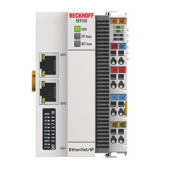
Page 14: Ek9500 - Introduction
EtherCAT Box modules (EPxxxx) and converts the telegrams from Ethernet/IP to E-bus signal representation. One station consists of an EK9500 and EtherCAT Terminals. RJ45 is used for the Ethernet/IP connection. In EtherCAT, the Ethernet/IP coupler has at its disposal a lower-level, powerful and ultra-fast I/O system with a large selection of terminals. -
Page 15: Technical Data
Approvals CE, cULus [} 25], ATEX [} 26] 1) The acyclic communication via GetAttributeSingle/SetAttributeSingle can be used to read and write > 1000 bytes. System data Ethernet/IP (EK9500) Number of I/O modules depending on controller Number of I/O points depending on controller Transmission medium... -
Page 16: Mounting And Wiring
• Each assembly must be terminated at the right hand end with an EL9011 or EL9012 bus end cap, to en- sure the protection class and ESD protection. Fig. 12: Spring contacts of the Beckhoff I/O components Version: 1.0.0 EK9500... -
Page 17: Dimensions
3.1.2 Dimensions The following illustrations show the dimensions of the Bus Couplers. Drawings in DWF and STEP format can be found in the Download section of the Beckhoff website. Fig. 13: EK9xxx – dimensions taking the EK9300 as an example 3.1.3 Installation on mounting rails –... -
Page 18: Fig. 15 Recommended Distances For Standard Installation Position
We recommend the installation in the horizontal position for optimum ventilation. Furthermore, it is not nec- essary with this installation position to check whether there are terminals present that may only be installed horizontally. Other installation positions are allowed, but not recommended. Version: 1.0.0 EK9500... -
Page 19: Wiring
Wiring 3.2.1 Power supply The power supply unit is equipped with an I/O interface, which permits connection of the Beckhoff Bus Terminals. The power is supplied via the upper spring-loaded terminals with the designations "24 V and "0 V". The supply voltage supplies the EK system and, via the terminal bus, the Bus Terminals with a voltage of 24 (-15%/+20 %). -
Page 20: Fig. 17 Bus Coupler Ek9Xxx Power Supply
The other LEDs indicate the Terminal Bus status. A detailed description of the LEDs can be found in section "LED troubleshooting". PE power contacts NOTE Power contact “PE” The "PE" power contact must not be used for other potentials. Version: 1.0.0 EK9500... -
Page 21: Ethernet
Ethernet connections Fig. 18: RJ45 interface Assignment of the RJ45 interface, port (switched) EK9xxx: X001 / X002 Signal Description TD + Transmit + TD - Transmit - RD + Receive + connected reserved RD - Receive - connected reserved EK9500 Version: 1.0.0... - Page 22 Twisted pair cable for 100 Mbit/s. It is necessary to use a higher cable quality and to employ appropriate hubs or switches in order to achieve the higher data rate. 10BaseF The 10BaseF standard describes several optical fiber versions. Version: 1.0.0 EK9500...
- Page 23 This identification refers to a cable with a shield for each of the two wires as well as an overall shield. Industrial Twisted-Pair The structure is similar to that of S/STP, but, in contrast to S/STP, it has only one pair of conductors. EK9500 Version: 1.0.0...
-
Page 24: Fig. 19 Ethernet/Ip Topology
EK9500 Ethernet/IP topology sample EK9500 The construction of the EK9500 can take place in a line, with adherence to the following points: - Maximum 20 couplers one behind the other - No switches should be used in the line Fig. 19: Ethernet/IP topology... -
Page 25: Ul Notice
Beckhoff EtherCAT modules are intended for use with Beckhoff’s UL Listed EtherCAT Sys- tem only. Examination For cULus examination, the Beckhoff I/O System has only been investigated for risk of fire and electrical shock (in accordance with UL508 and CSA C22.2 No. 142). For devices with Ethernet connectors Not for connection to telecommunication circuits. -
Page 26: Atex - Special Conditions (Standard Temperature Range)
80°C at the wire branching points, then cables must be selected whose tempera- ture data correspond to the actual measured temperature values! • Observe the permissible ambient temperature range of 0 to 55°C for the use of Beckhoff fieldbus compo- nents standard temperature range in potentially explosive areas! •... -
Page 27: Atex Documentation
Notes about operation of the Beckhoff terminal systems in potentially explosive ar- eas (ATEX) Pay also attention to the continuative documentation Notes about operation of the Beckhoff terminal systems in potentially explosive areas (ATEX) that is available in the download area of the Beckhoff homepage http:\\www.beckhoff.com! EK9500... -
Page 28: Parameterization And Commissioning
The IP address or the mode (e.g. DHCP) can be set using the DIP switch. Furthermore, an HTML page is available for the configuration. DIP switch Ten-pole DIP switch S001 The DIP switch has the following meaning for the Ethernet interfaces X001 and X002, which are switched: Version: 1.0.0 EK9500... -
Page 29: Fig. 21 Dip Switch S001: Left Off "0", Right On "1
The EK starts in Config Mode; the internal Flash memory can be accessed via the USB interface (for example for an image update). 1 off and 2 on Factory setting 1 on and 2 on No function so far EK9500 Version: 1.0.0... -
Page 30: Configuration
Fig. 22: Configuration via HTML pages - information diagnostic page Boot Opt The Boot Opt allows you to enable/disable Remote Display. You can also restore the factory settings and trigger a manual reboot of the device. Fig. 23: Configuration via HTML pages – Boot Options Version: 1.0.0 EK9500... -
Page 31: Ethercat Configuration
Configuration Network-Interface The network interface enables you to set the IP address. Please note that the DIP switch of the EK9500 takes precedence and its setting applies regardless of what you set in the dialog Fig. 24: Configuration via HTML pages - network interface Example DIP switch DIP 1 = on;... -
Page 32: Fig. 25 Configuration Via Html Pages - Ethercat Configuration
Configuration Fig. 25: Configuration via HTML pages - EtherCAT configuration Version: 1.0.0 EK9500... -
Page 33: Fig. 26 Configuration Via Html Pages - Parameterizing Ethercat Terminals
The current state of the EtherCAT Master on the EK coupler is displayed here. It should usually be in the OP state. Network Statistics The EtherCAT statistics are output here. EtherCAT Slaves Display of the EtherCAT slaves and their states. The Restore State indicates whether a Restore File has been created for the terminals. EK9500 Version: 1.0.0... -
Page 34: Ethernet/Ip Configuration
Restore file overwrites EtherNet/IP modifications If the Restore File is used, the object parameters are always loaded into the terminal on starting the coupler. This will overwrite changes that you have made via the web page. EtherNet/IP Configuration EtherNet/IP Slave: Version: 1.0.0 EK9500... -
Page 35: Fig. 28 Configuration Via Html Pages - Ethernet/Ip Configuration
Configuration Fig. 28: Configuration via HTML pages – EtherNet/IP configuration EtherNet/IP Device (Slave) - Device Info All Parameters are “read only” and are for diagnostic purposes EtherNet/IP Adapter (Slave) – Settings • Error Confirmation Mode EK9500 Version: 1.0.0... -
Page 36: Fig. 29 Ethernet Statistics
Enable/Disable UDP Checksum – Multicast (Copies of Frames sent to Multiple Destinations). Checksum is a digit representing the sum of the transmitted data used for error checking. Ethernet Statistics Fig. 29: EtherNet Statistics Ethernet Rx Frames: Received Frames Ethernet Tx Frames: Transmitted Frames Version: 1.0.0 EK9500... -
Page 37: Fig. 30 Ip Stack Statistics
Dropped Frames: Indicates the number of dropped frames Electronic Data Sheet Create EDS File: Create an Electronic Data Sheet for Use with an EIP Master Create L5X File: Create UDTs for Input and Output Data (For use with RSLogix 5000 Import Only) EK9500 Version: 1.0.0... -
Page 38: Ethernet/Ip Mapping
EtherCAT devices are then invalid and the output data are no longer accepted. This also applies to the devices that are still in operation on the EK9500. If you wish to use the option to plug in or unplug devices during the runtime, a further “Sync Unit”... -
Page 39: Fig. 32 Sample Configuration With Ek1100 Ethercat Coupler
"Message to E-bus". If there is a "-" here, this terminal need not be taken into account for the mapping. EtherCAT devices are registered in the direction of the EtherCAT telegram. Sample configuration with EK1100 EtherCAT coupler Fig. 32: Sample configuration with EK1100 EtherCAT coupler EK9500 Version: 1.0.0... -
Page 40: Fig. 33 Sample Configuration With Epxxxx Ethercat Box
E-bus on the right-hand side (3). Fig. 34: Sample configuration with EK1122 2-port EtherCAT junction If neither junction is used, then junctions 1 and 2 are bridged, so to speak, and the EtherCAT frame goes directly to the E-Bus on the right-hand side. Version: 1.0.0 EK9500... -
Page 41: Fig. 35 Sample Configuration With Ep1122 (2-Port Ethercat Junction In Protection Class Ip65)
No Hot Swap during operation You cannot use the EP1122 and EK1122 on an EKxxxx for Hot Swap and also not for connection and disconnection during operation. EP1122 and EK1122 are suitable only for topology extensions (star) on an EKxxxx. EK9500 Version: 1.0.0... -
Page 42: Error Handling And Diagnosis
Error handling and diagnosis Error handling and diagnosis LED indicators Fig. 36: EK9500 LEDs Ethernet interface Interface X001/X002 Ethernet Meaning LED green On/flickering (blinking) Link available/activity LED yellow is not used LED on the coupler Labelling Meaning Color Meaning Indicates the... - Page 43 Flashing fast: EtherCAT Scanning; time: different (depending on the number and type of EtherCAT participants) Red/green Yellow Flashing slow: EtherCAT COE reading; time: different (depending on the number and type of EtherCAT participants) Green Start up is finished EK9500 Version: 1.0.0...
-
Page 44: Fig. 37 Leds On Power Supply Terminal
2 Up 24 V (top right, 1 row) Power contacts supply on: connected to: 24 V voltage 3 L/A (left center, 2 row) EtherCAT LED flashing green: EtherCAT communication active on: E-bus connected / no data traffic off: E-bus not connected Version: 1.0.0 EK9500... -
Page 45: Appendix
PC via a USB cable. Windows then shows the Bus Coupler as a removable data storage device, and the files can be copied. The Bus Coupler should only be updated after consultation with the Beckhoff Service. The Beckhoff Service will provide all the required files. -
Page 46: Setting Up The Ek9500 In Rs Logix Studio 5000 Via Eds File
• Create detailed description (only valid for current configuration) – using only one coupler in your project This is an example of how to set up the EK9500 in RS Logix Studio 5000 using the EDS File that can be exported from the Device Manager: Click on the “Create EDS File”... -
Page 47: Fig. 41 Search For The Ek9500 In Rs Logix Studio 5000
Appendix Search for the EK9500 (This will only work after you have imported the EDS file): Fig. 41: Search for the EK9500 in RS Logix Studio 5000 Enter the IP Address that was configured for the EK9500 and then click on Change: Fig. 42: Set the IP Address of the EK9500 in RS Logix Studio 5000... -
Page 48: Setting Up An Ek9500 As A Generic Device In Rs Logix Studio 5000
For RS Logix Studio it is possible to generate a data structure for in and output to get a easier mapping information about the connected EtherCAT terminals or modules (“module-defined”). Setting up an EK9500 as a Generic Device in RS Logix Studio 5000 Configure your Rockwell Hardware accordingly in RS Logix Studio 5000. - Page 49 Enter a name for your Generic Module (EK9500_1 in the example). Enter the IP Address that was set on the EK9500. The Data type can be set to SINT, INT, DINT or any other optional data type as long as the total number of BYTES is equal to what is shown in the Device Manager EtherNET/IP Mapping.
-
Page 50: Using The Ctrlstatus Dword
0x10 E-bus fixed after error. Outputs are disabled and have to be reset manually with the control DWORD. 0x04 E-bus error. In the event of an E-bus error, the EK9500 Bus Coupler continues to exchange data with the EtherNet/IP scanner (master). However, the input data are invalid. The cause of the error is coded in the high byte, the position in the low byte of the counter. - Page 51 Appendix There is one instance(=1) of this object in EK9500. Class Attribute List no class attributes implemented Instance Attribute List Attr ID Access Name (Struct.) Data Type Description Rule Vendor ID UINT (16) 106, the vendor ID of Beckhoff. Device Type...
-
Page 52: Faq
No, devices from other vendors can only be used with a CX (see CX8095 or similar products). I would like to operate the drive terminals/drives on the EK9500. Is that possible? No, use a CX with a suitable performance for this, e.g. CX9020 or higher. - Page 53 Configuration software for Bus Terminals, Bus Couplers, Bus Terminal Controllers, fieldbus box modules, etc. The PE power contact can be used as a protective earth. TwinCAT The Windows Control and Automation Technology, programmer and configuration tool from the BECKHOFF Automation. EK9500 Version: 1.0.0...
-
Page 54: Support And Service
Beckhoff's branch offices and representatives Please contact your Beckhoff branch office or representative for local support and service on Beckhoff products! The addresses of Beckhoff's branch offices and representatives round the world can be found on her internet pages: http://www.beckhoff.com You will also find further documentation for Beckhoff components there. - Page 55 LEDs on power supply terminal ....................Fig. 38 Setting up the EK9500 in RS Logix Studio 5000 via EDS File - Create generic description ..Fig. 39 Setting up the EK9500 in RS Logix Studio 5000 via EDS File - Create detailed description ..
- Page 56 List of illustrations Fig. 42 Set the IP Address of the EK9500 in RS Logix Studio 5000 ............Fig. 43 Set the Size of your Input and Output Instances in RS Logix Studio 5000........Fig. 44 Add a Generic Module to your hardware configuration in RS Logix Studio 5000......
Need help?
Do you have a question about the EK9500 and is the answer not in the manual?
Questions and answers