
Related Manuals for Beckhoff EP6224


Summary of Contents for Beckhoff EP6224
- Page 1 Documentation EP6224 and EP6228 IO-Link Master with protection class IP67 Version: Date: 2019-10-28...
-
Page 3: Table Of Contents
5.2.7 Activating the configuration.................... 39 Object description and parameterization .................. 40 5.3.1 Objects for commissioning.................... 40 5.3.2 Objects for regular operation ................... 42 5.3.3 Standard objects (0x1000-0x1FFF) ................. 42 5.3.4 Profile specific objects (0x6000-0xFFFF) ................ 46 EP6224 and EP6228 Version: 1.5... - Page 4 IO-Link Events .......................... 49 ADS Error Codes .......................... 50 7 Appendix .............................. 52 General operating conditions...................... 52 EtherCAT Box- / EtherCAT P Box - Accessories ................ 53 General note on the introduction of the Beckhoff Identification Code (BIC) ........ 54 Support and Service ........................ 56 Version: 1.5 EP6224 and EP6228...
-
Page 5: Foreword
EP1590927, EP1789857, EP1456722, EP2137893, DE102015105702 with corresponding applications or registrations in various other countries. ® EtherCAT is registered trademark and patented technology, licensed by Beckhoff Automation GmbH, Germany. Copyright © Beckhoff Automation GmbH & Co. KG, Germany. The reproduction, distribution and utilization of this document as well as the communication of its contents to others without express authorization are prohibited. -
Page 6: Safety Instructions
All the components are supplied in particular hardware and software configurations appropriate for the application. Modifications to hardware or software configurations other than those described in the documentation are not permitted, and nullify the liability of Beckhoff Automation GmbH & Co. KG. Personnel qualification This description is only intended for trained specialists in control, automation and drive engineering who are familiar with the applicable national standards. -
Page 7: Documentation Issue Status
• EP6228-x0x2 – Technical Data updated • Safety instructions adapted to IEC 82079-1. 1.2.4 • EP6228-3032 added • EP6224-x022 – Technical Data updated • EP6228-x0x2 – Technical Data updated • EP6228-x0x2 – Introduction updated • EP622x Module overview updated • Conductor losses 7/8" added •... - Page 8 02 - firmware version 02 01 - hardware version 01 Beckhoff Identification Code (BIC) The Beckhoff Identification Code contains additional information about the delivery state of the module: General note on the introduction of the Beckhoff Identification Code (BIC) [} 54]. Version: 1.5...
-
Page 9: Product Overview
4 x Class A 1.4 A 16.0 A 4.0 A 16.0 A EP6228-3132 [} 15] 4 x Class B This output current is additionally the maximum sum current for a port pair. The port pairs are specified in the Technical Data [} 17]. EP6224 and EP6228 Version: 1.5... -
Page 10: Introduction
Fig. 3: EP6224-3022 IO-Link master The EP6224 IO-Link module enables connection of up to four IO-Link devices, e.g. actuators, sensors or combinations of both. A point-to-point connection is used between the terminal and the device. The terminal is parameterised via the EtherCAT master. IO-Link is designed as an intelligent link between the fieldbus level and the sensor, wherein parameterisation information can be exchanged bidirectionally via the IO-Link connection. - Page 11 Product overview In the standard setting, the EP6224 functions as a 4-channel input terminal, 24 V DC, which communicates with connected IO-Link devices, parameterises them and, if necessary, changes their operating mode. Quick Links Installation [} 22] Commissioning [} 36] EP6224 and EP6228...
-
Page 12: Technical Data
Mechanics Weight approx. 250 g Mounting position variable Approvals and conformity Approvals CE, cURus Sum current of consumers and power transmission. This value corresponds to the current carrying capacity of the connections for the supply voltages. Version: 1.5 EP6224 and EP6228... -
Page 13: Scope Of Supply
Scope of supply Make sure that the following components are included in the scope of delivery: • 1x EtherCAT Box EP6224 • 1x protective cap for supply voltage input, M8, transparent (pre-assembled) • 1x protective cap for supply voltage output, M8, black (pre-assembled) •... -
Page 14: Process Image
Module 5 DeviceState Inputs State Ch3 Module 2 Module 6 DeviceState Inputs State Ch4 The modules "Module 3" to "Module 6" only exist in the process data if the corresponding IO-Link ports have been configured [} 37]. Version: 1.5 EP6224 and EP6228... -
Page 15: Introduction
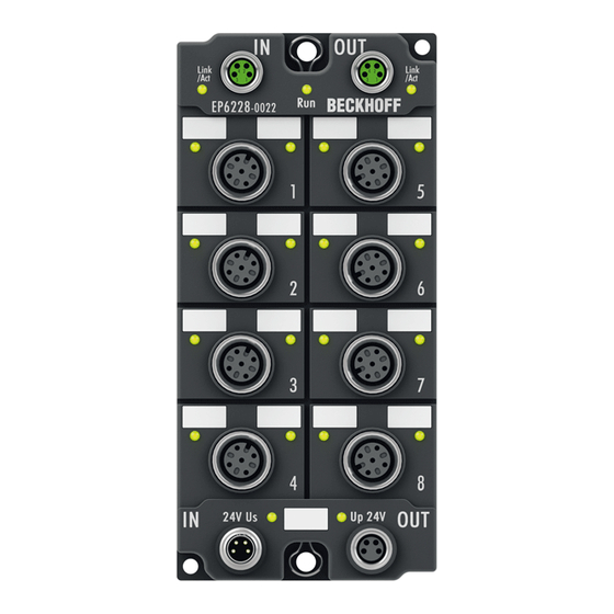
Product overview EP6228 2.4.1 Introduction Fig. 4: EP6228-0022 Fig. 5: EP6228-3032 EP6224 and EP6228 Version: 1.5... -
Page 16: Fig. 6 Ep6228-3132
TwinCAT via ADS or very conveniently via the integrated IO-Link configuration tool. In the standard setting, the EP6228 functions as a 8-channel input terminal, 24 V DC, which communicates with connected IO-Link devices, parameterises them and, if necessary, changes their operating mode. Quick Links Dimensions [} 22] Commissioning [} 36] Version: 1.5 EP6224 and EP6228... -
Page 17: Technical Data
Sum current of consumers and power transmission. This value corresponds to the current carrying capacity of the connections for the supply voltages. Port pairs with common limitation of the actuator supply: • EP6228-3032: Port pair 1+5, 2+6, 3+7, 4+8 • EP6228-3132: Port pair 3+7, 4+8 EP6224 and EP6228 Version: 1.5... -
Page 18: Scope Of Supply
Pre-assembled protective caps do not ensure IP67 protection Protective caps are pre-assembled at the factory to protect connectors during transport. They may not be tight enough to ensure IP67 protection. Ensure that the protective caps are correctly seated to ensure IP67 protection. Version: 1.5 EP6224 and EP6228... -
Page 19: Process Image
Module 9 DeviceState Inputs State Ch7 Module 2 Module 10 DeviceState Inputs State Ch8 The modules "Module 3" to "Module 10" only exist in the process data if the corresponding IO-Link ports have been configured [} 37]. EP6224 and EP6228 Version: 1.5... -
Page 20: Io-Link Master Principles
Contacts of a class B port: • Two electrically isolated supply voltages for the IO-Link device: ◦ Sensor/logic supply: L+, L- ◦ Actuator supply: P24, N24 • Data cable for serial communication or switching signals: C/Q Version: 1.5 EP6224 and EP6228... - Page 21 If a device fails, its parameters remain in the memory of the IO-Link Master. If a defective device is replaced by a new, identical device, the master can automatically parameterize the new device with the stored parameters. EP6224 and EP6228 Version: 1.5...
-
Page 22: Mounting And Access
Metal parts brass, nickel-plated Contacts CuZn, gold-plated Power feed through max. 4 A Mounting position variable Protection class IP65, IP66, IP67 (conforms to EN 60529) when screwed together Dimensions (H x W x D) approx. 126 x 60 x 26.5 mm (without connectors) Version: 1.5 EP6224 and EP6228... -
Page 23: Fig. 9 Dimensions
Metal parts brass, nickel-plated Contacts CuZn, gold-plated Power feed through max. 4 A Mounting position variable Protection class IP65, IP66, IP67 (conforms to EN 60529) when screwed together Dimensions (H x W x D) approx. 126 x 60 x 26.5 mm (without connectors) EP6224 and EP6228 Version: 1.5... -
Page 24: Fig. 10 Dimensions
Power feed through max. 16 A at 40°C (according to IEC 60512-3) Mounting position variable Protection class IP65, IP66, IP67 (conforms to EN 60529) when screwed together Dimensions (H x W x D) approx. 150 x 60 x 26.5 mm (without connectors) Version: 1.5 EP6224 and EP6228... -
Page 25: Mounting
• Protect the plug connectors against dirt during the assembly. Mount the module with two M4 screws in the centrally located fastening holes. 4.1.3 Tightening torques for plug connectors Screw connectors tight with a torque wrench. (e.g. ZB8801 from Beckhoff) Connector diameter Tightening torque 0.4 Nm 0.6 Nm... -
Page 26: Connection
Connection Guidelines Follow these guidelines to ensure IP67 protection: • Mount connectors with the specified torque [} 25]. Use a torque wrench, e.g. Beckhoff ZB8801. • Seal unused connectors with protective caps. • Ensure the correct seating of pre-assembled protective caps. -
Page 27: Supply Voltage
Feed-in Forwarding Fig. 12: M8 connector Contact Function Description Core color Control voltage Brown Peripheral voltage White GND to U Blue GND to U Black The core colors apply to cables of the type: Beckhoff ZK2020-xxxx-xxxx EP6224 and EP6228 Version: 1.5... -
Page 28: Fig. 13 Status Leds For The Supply Voltages
Vert. Faktor: 0,45 cm / V Vert. Faktor: 0,4 0,34 mm² Vert. Faktor: 0,45 cm / V Vert. Faktor: 0,5 mm² 0,25 mm² 0,34 mm² 0,75 mm² 0,5 mm² 0,75 mm² Cable length (m) Cable length (m) Version: 1.5 EP6224 and EP6228... -
Page 29: Fig. 14 Connector For The Supply Voltages
Fig. 15: 7/8" plug connectors Contact Function Description Core color GND to U Black GND to U Blue Functional earth Grey Control voltage Brown Peripheral voltage White The core colors apply to cables of the type: Beckhoff ZK203x-xxxx. EP6224 and EP6228 Version: 1.5... -
Page 30: Fig. 16 Status Leds For The Supply Voltages
Voltage drop on the supply line I = 2 A I = 4 A 1,5 mm² 2,5 mm² Vert. Faktor: 2,75 cm / V Vert. Faktor: 1,5 mm² 2,5 mm² Cable length (m) Cable length (m) Version: 1.5 EP6224 and EP6228... -
Page 31: Ethercat
For standardization, the core colors of the ZB9030, ZB9032 and ZK1090-3xxx-xxxx cables have been changed to the EN61918 core colors: yellow, orange, white, blue. So there are different color codes in circulation. The electrical properties of the cables have been retained when the core colors were changed. EP6224 and EP6228 Version: 1.5... -
Page 32: Fig. 19 Ethercat Status Leds
(CAT5) according to EN 50173 or ISO/IEC 11801 should be used. EtherCAT uses four wires for signal transmission. Thanks to automatic line detection ("Auto MDI-X"), both symmetrical (1:1) or cross-over cables can be used between Beckhoff EtherCAT. Detailed recommendations for the cabling of EtherCAT devices Version: 1.5 EP6224 and EP6228... -
Page 33: Io-Link
Actuator supply (U white GND to L+ blue IO-Link data cable IO-Link data cable black GND to P24 grey The core colors apply to M12 sensor cables from Beckhoff: • ZK2000-5xxx • ZK2000-6xxx • ZK2000-7xxx. EP6224 and EP6228 Version: 1.5... -
Page 34: Fig. 21 Status Leds Of An Io-Link Port
IO-Link communication active green illuminated Logic level high Port configured as digital input or output 2 - Digital input DI (EP6228-3132 only) The LED lights up when a high level is present on the digital input DI. Version: 1.5 EP6224 and EP6228... -
Page 35: Ul Requirements
To meet the UL requirements, EtherCAT Box Modules has to be operated only at an ambient temperature range of 0 to 55°C! Marking for UL All EtherCAT Box Modules certified by UL (Underwriters Laboratories) are marked with the following label. Fig. 22: UL label EP6224 and EP6228 Version: 1.5... -
Page 36: Commissioning And Configuration
An EtherCAT Box must be configured in TwinCAT so that its functions can be used in a PLC program. The following link will take you to a quick start guide describing the configuration of an EtherCAT Box in TwinCAT: https://infosys.beckhoff.com/content/1033/epioconfiguration/index.html?id=6991403443235907429 Version: 1.5 EP6224 and EP6228... -
Page 37: Io-Link Configuration
The right-hand field "Catalog" shows the device catalog. The device catalog contains a list of the IO- Link devices for which a device description exists in the local TwinCAT installation. Changes in the IO-Link configuration tool only become effective when you activate the IO-Link configuration [} 39]. EP6224 and EP6228 Version: 1.5... -
Page 38: Assigning Devices To Ports
Supplementing the device catalog Following the installation of TwinCAT, the device catalog contains only the device descriptions of IO- Link devices from Beckhoff. There are two ways of supplementing the catalog: Importing from the online database "IODDfinder" ü Requirement: the PC can access the Internet 1. -
Page 39: Parameterizing A Port
Changes in the IO-Link configuration tool only become effective when you activate the IO-Link configuration. There are two ways to activate the IO-Link configuration: • Click on the "Reload Devices" button • Activate the TwinCAT configuration: Click on the "Activate Configuration" button EP6224 and EP6228 Version: 1.5... -
Page 40: Object Description And Parameterization
EtherCAT XML Device Description The display matches that of the CoE objects from the EtherCAT XML Device Description. We rec- ommend downloading the latest XML file from the download area of the Beckhoff website and in- stalling it according to installation instructions. - Page 41 (indicates whether the value in LENGTH interpreted as bit length [bit not set] or as byte length + 1 [bit set] Bit 6: (indicates whether the device supports the standard IO mode [bit set]) Bit 0 to 4: LENGTH (length of the process data) EP6224 and EP6228 Version: 1.5...
-
Page 42: Objects For Regular Operation
Data type Flags Default 1009:0 Hardware version Hardware version of the EtherCAT slaves STRING Index 100A Software version Index (hex) Name Meaning Data type Flags Default 100A:0 Software version Firmware version of the EtherCAT slaves STRING Version: 1.5 EP6224 and EP6228... - Page 43 Index 1A00 IO TxPDOPDO-Map Ch.1 Index (hex) Name Meaning Data type Flags Default 1A00:0 IO TxPDOPDO-Map PDO Mapping TxPDO 1 UINT8 0x01 (1 Ch.1 1A00:01 SubIndex 001 1. PDO Mapping entry (8 bits align) UINT32 0x0000:00, 8 EP6224 and EP6228 Version: 1.5...
- Page 44 3. assigned RxPDO (contains the index of the corre- UINT16 0x1602 sponding RxPDO Mapping object) (5634 1C12:04 SubIndex 004 4. assigned RxPDO (contains the index of the corre- UINT16 0x1603 sponding RxPDO Mapping object) (5635 Version: 1.5 EP6224 and EP6228...
- Page 45 Shift too short counter Number of the too short distances between SYNC0 UINT16 0x0000 (0 and SYNC1 Event (only in DC Mode) 1C32:20 Sync error TRUE: In the last cycle the synchronization was not BOOLEAN 0x00 (0 correct (only in DC Mode) EP6224 and EP6228 Version: 1.5...
-
Page 46: Profile Specific Objects (0X6000-0Xffff)
Index 70n0 IO Outputs Ch.1 - 4 (for 0 ≤ n ≤ 3) Index (hex) Name Meaning Data type Flags Default 70n0:0 IO Outputs Ch.1 - 4 Max. Subindex UINT8 0x00 (0 70n0:01 Subindex 001 IO-Link output process data 70n0:10 Subindex 016 IO-Link output process data Version: 1.5 EP6224 and EP6228... - Page 47 Bit 6: (indicates whether the device supports the standard IO mode [bit set]) Bit 0 bis 4: LENGTH (length of the process data) 90n0:26 Reserved reserved UINT16 0x0000 (0 90n0:27 Reserved2 reserved UINT16 0x0000 (0 EP6224 and EP6228 Version: 1.5...
- Page 48 F100:04 State Ch4 Statusbyte Ch. 4 UINT8 0x00 (0 Index F900 Info data Index (hex) Name Meaning Data type Flags Default F900:0 Info data Max. Subindex UINT8 0x09 (9 F900:01 IO-Link Version UINT8 0x10 (16 Version: 1.5 EP6224 and EP6228...
-
Page 49: Diagnosis
0. • Export Diag History: the events that have occurred can be exported as a "txt" file and thus archived. • Advanced: this field currently (as at 3 quarter 2015) has no function. EP6224 and EP6228 Version: 1.5... -
Page 50: Ads Error Codes
IO-Link connection inter- rupted Device application er- remote S_APP_DEV** ERROR SiNGLE Service PDU transferred, but SHOT not processed due to device er- ror. See error details in Addi- tional Code** Version: 1.5 EP6224 and EP6228... - Page 51 Service PDU transferred, but not processed due to device error. See error details in Additional Code Application not ready Service PDU transferred, but not processed due to device error. See error details in Additional Code EP6224 and EP6228 Version: 1.5...
-
Page 52: Appendix
(ph-Value > 12) > 40°C: not resistant Acetic acid not resistant Argon (technical clean) resistant • resistant: Lifetime several months • non inherently resistant: Lifetime several weeks • not resistant: Lifetime several hours resp. early decomposition Version: 1.5 EP6224 and EP6228... -
Page 53: Ethercat Box- / Ethercat P Box - Accessories
ZB8801-0003 torque cable key, M12 field assembly/wrench size 13, for torque wrench ZB8801-0000 Further accessories Further accessories may be found at the price list for Beckhoff fieldbus components and at the inter- net under https://www.beckhoff.com EP6224 and EP6228 Version: 1.5... -
Page 54: General Note On The Introduction Of The Beckhoff Identification Code (Bic)
Identification Code (BIC) General In future you will increasingly find machine-readable information on Beckhoff products in the form of a Data Matrix Code (DMC, ECC200). This helps us to improve the quality assurance process, beyond which you can use it for better identification of our products. - Page 55 Article description Quantity An important component of the BIC is the Beckhoff Traceability Number (BTN, item no. 2). The BTN is a unique 8-character serial number that in future will replace all other serial number systems at Beckhoff (e.g. batch designations on IO components, hitherto serial number circle for safety products, etc.). The BTN is likewise being introduced gradually, so it may be the case that the BTN is not yet coded in the BIC.
-
Page 56: Support And Service
Beckhoff's branch offices and representatives Please contact your Beckhoff branch office or representative for local support and service on Beckhoff products! The addresses of Beckhoff's branch offices and representatives round the world can be found on her internet pages: http://www.beckhoff.com You will also find further documentation for Beckhoff components there. - Page 57 EtherCAT connector ........................Fig. 18 M8 socket ............................ Fig. 19 EtherCAT Status LEDs ........................ Fig. 20 M12 socket ..........................Fig. 21 Status LEDs of an IO-Link port ....................Fig. 22 UL label............................Fig. 23 DiagHistory tab ..........................EP6224 and EP6228 Version: 1.5...
Need help?
Do you have a question about the EP6224 and is the answer not in the manual?
Questions and answers