Table of Contents
Advertisement
Quick Links
Advertisement
Chapters
Table of Contents

Subscribe to Our Youtube Channel
Related Manuals for Beckhoff EP7211-0034


Summary of Contents for Beckhoff EP7211-0034
- Page 1 Documentation EP7211 Servomotor module with OCT Version: Date: 2019-08-01...
-
Page 3: Table Of Contents
Table of contents Table of contents 1 Foreword .............................. 5 Notes on the documentation...................... 5 Safety instructions .......................... 6 Documentation issue status ...................... 7 2 Product overview............................ 8 EtherCAT Box - Introduction...................... 8 EP7211-x034 - Introduction ...................... 10 Technical data .......................... 11 Scope of supply .......................... 12 Technology ............................ 13 3 Mounting and cabling.......................... 15 Mounting ............................ 15 3.1.1... - Page 4 FPGA firmware *.rbf....................... 136 5.2.5 Simultaneous updating of several EtherCAT devices............ 140 EtherCAT Box- / EtherCAT P Box - Accessories ................ 141 Servo technology - accessories..................... 141 General note on the introduction of the Beckhoff Identification Code (BIC) ........ 142 Support and Service ........................ 144 Version: 1.0 EP7211...
-
Page 5: Foreword
EP1590927, EP1789857, EP1456722, EP2137893, DE102015105702 with corresponding applications or registrations in various other countries. ® EtherCAT is registered trademark and patented technology, licensed by Beckhoff Automation GmbH, Germany. Copyright © Beckhoff Automation GmbH & Co. KG, Germany. The reproduction, distribution and utilization of this document as well as the communication of its contents to others without express authorization are prohibited. -
Page 6: Safety Instructions
All the components are supplied in particular hardware and software configurations appropriate for the application. Modifications to hardware or software configurations other than those described in the documentation are not permitted, and nullify the liability of Beckhoff Automation GmbH & Co. KG. Personnel qualification This description is only intended for trained specialists in control, automation and drive engineering who are familiar with the applicable national standards. -
Page 7: Documentation Issue Status
HH - hardware version 01 - hardware version 01 Beckhoff Identification Code (BIC) The Beckhoff Identification Code contains additional information about the delivery state of the module: General note on the introduction of the Beckhoff Identification Code (BIC) [} 142]. EP7211... -
Page 8: Product Overview
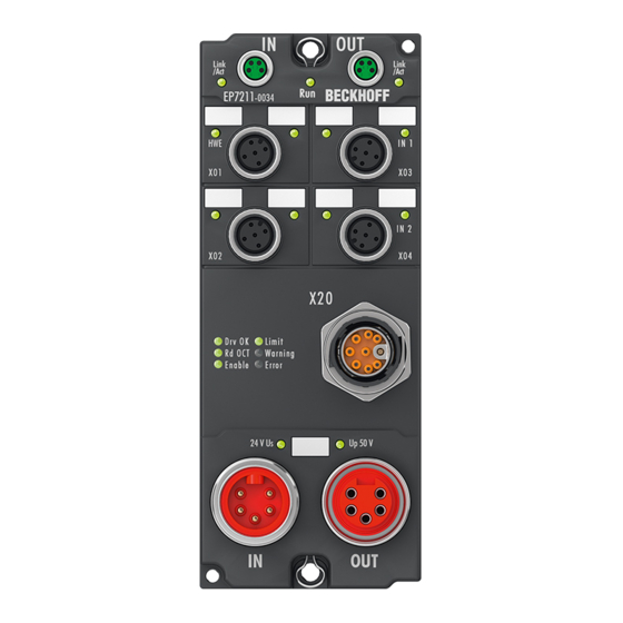
Product overview Product overview EtherCAT Box - Introduction The EtherCAT system has been extended with EtherCAT Box modules with protection class IP 67. Through the integrated EtherCAT interface the modules can be connected directly to an EtherCAT network without an additional Coupler Box. The high-performance of EtherCAT is thus maintained into each module. The extremely low dimensions of only 126 x 30 x 26.5 mm (h x w x d) are identical to those of the Fieldbus Box extension modules. -
Page 9: Fig. 2 Ethercat Box With M8 Connections For Sensors/Actuators
EtherCAT, which is available for download from our website (www.beckhoff.com) under Downloads. EtherCAT XML Device Description You will find XML files (XML Device Description Files) for Beckhoff EtherCAT modules on our web- site (www.beckhoff.com) under Downloads, in the Configuration Files area. -
Page 10: Ep7211-X034 - Introduction
◦ Electronic identification plate readout • 2 x touch probe • Hardware Enable (EP7211-0034): digital input for activating the output stage • Safe Torque Off (EP7211-9034) The motor is connected via a hybrid cable. The hybrid cable contains the wires for the motor phases, the brake and the OCT communication. -
Page 11: Technical Data
Product overview Technical data Technical data EP7211-0034 EP7211-9034 Fieldbus Fieldbus EtherCAT Connection 2 x M8 socket (green) Electrical isolation 500 V (fieldbus / IO) Distributed Clocks Process image Dependent on the operation mode [} 62] Supply Connection Feed: 1 x 7/8" plug, 5-pin [} 18] Downstream connection: 1 x 7/8"... -
Page 12: Scope Of Supply
CE, UL in preparation Scope of supply Make sure that the following components are included in the scope of delivery: • 1x EtherCAT Box EP7211-0034 / EP7211-9034 • 2x protective caps for EtherCAT socket (mounted) • 1x protective cap for 7/8" socket (mounted) •... -
Page 13: Technology
Product overview Technology Servomotor The servomotor is an electrical motor. Together with a servo drive the servomotor forms a drive. The servomotor is operated in a closed control loop with position, torque or speed control. EP7211-x034 supports control of permanent magnet synchronous motors. These consist of 3 coils which are offset by 120°... -
Page 14: Fig. 6 Limitation To The Rated Motor Current
Product overview Fig. 6: Limitation to the rated motor current Version: 1.0 EP7211... -
Page 15: Mounting And Cabling
Mounting and cabling Mounting and cabling Mounting 3.1.1 Dimensions Ø 4.5 Fig. 7: Dimensions All dimensions are given in millimeters. Housing features Housing material PA6 (polyamide) Sealing compound polyurethane Mounting two fastening holes Ø 4.5 mm for M4 Metal parts brass, nickel-plated Contacts CuZn, gold-plated Power feed through max. -
Page 16: Fixing
Connect the functional earth of the "FE" cores in accordance with the following instructions: • If the remote station is a device with a 7/8" connector: connect the devices with a pre-configured cable. Possible types of preconfigured cables: ◦ Beckhoff ZK2030-1112-0xxx ◦ Beckhoff ZK2030-1114-0xxx ◦ Beckhoff ZK2030-1314-0xxx •... -
Page 17: Cabling
Hardware Enable / Safe Torque Off [} 24] 0.6 Nm Touch Probe [} 27] iTec M23 Motor, brake and feedback system [} 22] 0.4 Nm EtherCAT [} 20] 7/8" 1.5 Nm Power supply [} 18] Mount connectors on these plug connectors using a torque wrench, e.g. ZB8801 from Beckhoff. EP7211 Version: 1.0... -
Page 18: Power Supply
Core colors GND to U Black GND to U Blue Functional earth Grey +24 V Control voltage U Brown +48 V DC link voltage U White The core colors apply to cables of the type: Beckhoff ZK203x-xxxx. Version: 1.0 EP7211... -
Page 19: Fig. 11 Power Supply Status Leds
Mounting and cabling 3.2.1.2 Status LEDs The status of the supply voltages is signaled by two LEDs. A Status LED lights up green when the respective supply voltage is present on the connector for the supply. Fig. 11: Power supply Status LEDs 3.2.1.3 Conductor losses Take into account the voltage drop on the supply line when planning a system. -
Page 20: Ethercat
Mounting and cabling 3.2.2 EtherCAT 3.2.2.1 Connection EtherCAT Boxes (EPxxxx) have two green M8 sockets for the incoming and outgoing EtherCAT connections. Fig. 13: EtherCAT connection Fig. 14: M8 socket pin assignment Assignment There are various different standards for the assignment and colors of connectors and cables for EtherCAT. EtherCAT Plug connector Cable... -
Page 21: Fig. 15 Ethercat Status Leds
Meaning Slave is in "Init" state flashes uniformly Slave is in "Pre-Operational“ state flashes sporadically Slave is in "Safe-Operational" state Slave is in "Operational" state A description of the EtherCAT slave states can be found under https://infosys.beckhoff.com/content/1033/ethercatsystem/1036980875.html?id=8582353789396071752. EP7211 Version: 1.0... -
Page 22: Motor, Brake And Feedback System
Data and supply for the OCT feedback system Blue Motor phase U Black Motor phase W Grey Motor phase V Brown FE, shield Functional earth, cable shield green-yellow The core colors apply to the ZK470x-xxxx motor cables from Beckhoff. Version: 1.0 EP7211... -
Page 23: Fig. 17 Status Leds Of The Motor Connection
Mounting and cabling 3.2.3.2 Status LEDs Fig. 17: Status LEDs of the motor connection LED Displays Display Meaning Drv OK green The driver stage is ready for operation. illuminated Rd OCT flashing green The electronic identification plate is being read. Enable green The driver stage is enabled. -
Page 24: Hardware Enable / Safe Torque Off
Mounting and cabling 3.2.4 Hardware Enable / Safe Torque Off EP7211-0034 and EP7211-9034 differ from each other by the purpose of use of the digital input "Hardware Enable" / "Safe Torque Off": Hardware variant Designation of the digital input Purpose of use of the digital input... -
Page 25: Fig. 19 Status Leds For Hwe/Sto
Mounting and cabling 3.2.4.2 Status LEDs EP7211-0034 EP7211-9034 Fig. 19: Status LEDs for HWE/STO EP7211-0034 The green LED with the name "HWE" (Hardware Enable) lights when a high level is present on the corresponding pin of X01 or X02. → The motor output stage is activated. -
Page 26: Fig. 20 Sample: Forwarded Hwe/Sto Signal
Mounting and cabling 3.2.4.3 Cabling The X01 and X02 sockets have the same configuration and are bridged 1:1 inside the box. This makes it possible to forward the signal for "Hardware Enable" / "Safe Torque Off" from one box to the next. Sample: Box 1 Box 2... -
Page 27: Touch Probe
IN A = TP1 Black n.c. Grey The core colors apply to cables of the types ZK2000-5xxx, ZK2000-6xxx and ZK2000-7xxx from Beckhoff. 3.2.5.2 Status LEDs Fig. 22: Touch probe Status LEDs The green LEDs with the names "IN A" and "IN B" light when a high level is present on the corresponding pins of X03 or X04: •... - Page 28 Mounting and cabling 3.2.5.3 Cabling The X03 and X04 sockets have the same configuration and are bridged 1:1 inside the box. This enables the touch probes to be wired in two ways: • One common cable (connection to X03 or X04) Cable •...
-
Page 29: Commissioning
An EtherCAT Box must be configured in TwinCAT so that its functions can be used in a PLC program. The following link will take you to a quick start guide describing the configuration of an EtherCAT Box in TwinCAT: https://infosys.beckhoff.com/content/1033/epioconfiguration/index.html?id=6991403443235907429 EP7211 Version: 1.0... -
Page 30: Start-Up And Parameter Configuration
Installation of the latest XML device description Please ensure that you have installed the corresponding latest XML device description in TwinCAT. This can be downloaded from the Beckhoff Website and installed according to the installation in- structions. Integration into the NC can be accomplished as follows: •... -
Page 31: Fig. 24 Adding A New Task
Commissioning Adding an axis manually • First add a new task. Right-click on NC configuration and select "Append Task..." (see Fig. Adding a new task). • Rename the task if required and confirm with OK. Fig. 24: Adding a new task •... -
Page 32: Fig. 26 Selecting And Confirming The Axis Type
Commissioning Fig. 26: Selecting and confirming the axis type • Left-click your axis to select it. On the Settings tab, select "Link To..." (see Fig. Linking the axis with the box). Fig. 27: Linking the axis with the box • Select the appropriate box (CANopen DS402, EtherCAT CoE) and confirm with "OK". Fig. 28: Selection of the correct box •... -
Page 33: Fig. 29 Automatic Linking Of All Main Variables
Commissioning Fig. 29: Automatic linking of all main variables • Several parameters have to be set before the motor can be started up. The values can be found in the chapters Settings in the CoE register [} 39] and NC settings [} 42]. Set these parameters before continuing with the motor commissioning. -
Page 34: Settings With The Drive Manager
4.3.2 Settings with the Drive Manager (Master TwinCAT 2.11 R3) The data given here serve as an example for a servomotor type AM8131-0F20-0000 from Beckhoff Automation. For other motors the values may vary, depending on the application. Table of contents Start-up with the Drive Manager [} 34]... -
Page 35: Fig. 31 Automatic Scanning Of The Connected Motor
Commissioning Fig. 31: Automatic scanning of the connected motor • If you decide to manually input the connected motor, please click on Select Motor. Fig. 32: Selecting the connected motor • Select the suitable motor in the selection window and confirm with Ok. EP7211 Version: 1.0... -
Page 36: Fig. 33 List Of Available Motors
Commissioning Fig. 33: List of available motors • Confirm the next dialog box with OK. All required parameters are automatically entered in the NC, and the scaling factor is calculated. If this is not confirmed, these settings have to be entered manually. See section NC settings [} 42]. -
Page 37: Fig. 35 Adapting The Scaling
Commissioning Fig. 35: Adapting the scaling All main parameters for the commissioning the motor are now set. The motor can now be commissioned with the NC, for example. A brief description can be found in section "Commissioning the motor with the NC". Or the NC can be addressed from the PLC. -
Page 38: Fig. 36 Adapting Tn
Commissioning Setting further parameters with the Drive Manager The values specified here are exemplary, although in most cases they have led to excellent results. Depending on the application, other values may yield better results. These values can be changed during operation. Click on Download to apply the values. Integral velocity controller component Tn •... -
Page 39: Settings In The Coe Register
4.3.3 Settings in the CoE register (Master TwinCAT 2.11 R3) The data given here serve as an example for a servomotor type AM8131-0F20-0001 from Beckhoff Automation. For other motors the values may vary, depending on the application. Table of contents Settings in the CoE register [} 39]... -
Page 40: Fig. 39 Selecting The Correct Motor Xml File
Commissioning Fig. 39: Selecting the correct motor XML file • All required parameters are then set, and the motor can be put into operation (see Fig. CoE parameters of the motor XML file). Fig. 40: CoE parameters of the motor XML file Startup list Any further application-specific settings should also be implemented in the Startup list. -
Page 41: Fig. 41 Multi-Turn / Single-Turn Bits
Commissioning Adaptation of current and voltage NOTE The motor may overheat! In order to prevent overheating of the connected motor, it is important to adjust the output voltage of the box to the actually connected voltage. This requires the index 0x8010:19 [} 86] (0x2002:19 [} 108], DS402 profile) "Nominal DC Link Voltage" of the connected voltage to be set accordingly Setting further parameters Single-turn bits (MDP742: Index 0x8000:12 [} 84] / DS402: Index 0x2010:12 [} 112]) /... -
Page 42: Nc Settings
4.3.4 NC settings (Master TwinCAT 2.11 R3) The data given here serve as an example for a servomotor type AM8122-0F20-0000 from Beckhoff Automation. For other motors the values may vary, depending on the application. Table of contents Definition of the unit [} 42] Selecting the maximum velocity [} 43]... -
Page 43: Fig. 43 Adjusting The Reference Velocity
Commissioning Selecting the maximum velocity The maximum permitted velocity is calculated based on the maximum motor speed (name plate) and the distance, in this case in relation to 360° per second. Fig. 43: Adjusting the reference velocity The reference velocity matches the maximum permitted velocity. Below that separate values for the maximum and minimum velocity for manual NC mode can be set. -
Page 44: Fig. 45 Setting The Encoder Mask
Commissioning Setting the encoder mask The maximum values for the encoder mask can be set in the Parameter tab for the Axis1_ENC encoder settings. EP7211 provides a maximum of 32 bits for the encoder. The parameter Encoder Mask (maximum encoder value) can be used to set the maximum number of available bits. -
Page 45: Fig. 46 Setting The Scaling Factor
Commissioning Calculation of the scaling factor Fig. 46: Setting the Scaling Factor Scaling output Enter the value 32 in the Parameter tab for the drive settings under Output Scaling (Velocity). Fig. 47: Output scaling Position lag monitoring The position lag monitoring function checks whether the current position lag of an axis has exceeded the limit value. -
Page 46: Fig. 48 Lag Monitoring
Commissioning NOTE Damage to equipment, machines and peripheral components possible! Setting the position lag monitoring parameters too high may result in damage to equipment, machines and peripheral components. Fig. 48: Lag monitoring Commissioning the motor with the NC • Once the parameters are set, the motor is basically ready for operation. Individual further parameters have to be adapted to the respective application. -
Page 47: Fig. 49 Enabling An Axis
Commissioning Fig. 49: Enabling an axis You can now move the axis with the function keys F1, F2 (Backward) or F3, F4 (Forward). You can adjust the Kv factor in order to approach a suitable factor. Set the value to 0 initially in order to set the correct reference velocity. -
Page 48: Commissioning Without Nc, Status Word/Control Word
Commissioning Fig. 50: Reversing Sequence The motor now turns to position 2, remains there for 2 seconds and returns to position 1. This is repeated until Stop is pressed. 4.3.5 Commissioning without NC, status word/control word (Master: TwinCAT 2.11 R3) In principle, the operating modes CST, CSTCA, CSV and CSP can be used without TwinCAT NC. Output stage enabled via control word The output stage has to be enabled for each operation mode. -
Page 49: Fig. 51 Ds402 State Machine
Commissioning Fig. 51: DS402 State Machine EP7211 Version: 1.0... - Page 50 Commissioning CST - cyclic synchronous torque Select Cyclic synchronous torque mode in index 0x7010:03 [} 94] Modes of operation (MDP) or 0x6060:0 [} 115] Modes of operation (DS402). In the respective process data, the Predefined PDO Assignment: 'Cyclic synchronous torque mode (CST)' should also be selected (see Process data MDP 742 [} 76] or DS402 process data [} 80]).
-
Page 51: Settings For The Automatic Configuration
Commissioning 4.3.6 Settings for the automatic configuration (Master TwinCAT 2.11 R3) The EP7211 offers the option of automatically configuring the connected motor from the AM81xx series. The electronic identification plate integrated in the motor is read and the necessary parameters of the box are adapted accordingly. -
Page 52: Fig. 52 Flow Chart For The Automatic Configuration
Commissioning Fig. 52: Flow chart for the automatic configuration Version: 1.0 EP7211... -
Page 53: Configure End Position Monitoring
Commissioning Parameter list of the automatic configuration The following parameters are affected by the automatic configuration. Index (hex) Name Meaning MDP 407 Profile DS402 Profile Current loop integral time is calculated according to the symmetrical optimum 8010:12 [} 86] 2002:12 [} 108] Current loop proportional gain is calculated according to the symmetrical optimum 8010:13 [} 86]... -
Page 54: Homing
Commissioning 4.3.8 Homing (Master TwinCAT 2.11 R3) The data given here serve as an example for a servomotor type AM8131-0F20-0000 from Beckhoff Automation. For other motors the values may vary, depending on the application. Table of contents Referencing [} 54] Function block "MC_Home" [} 54] Homing [} 55]... -
Page 55: Fig. 55 Configuration Of The Mc_Home Block
Commissioning Fig. 55: Configuration of the MC_Home block • The following figure Extract from the functional description for MC_Home shows an extract from the functional description of MC_Home. Full information can be found in the corresponding functional description. Fig. 56: Extraction from the functional description for MC_Home Reference modes •... -
Page 56: Fig. 57 Selection Of The Reference Modes In The Nc
Commissioning Fig. 57: Selection of the reference modes in the NC The velocity to be used for homing can also be set in the NC (Fig. Setting the reference velocity). Fig. 58: Setting the reference velocity Version: 1.0 EP7211... -
Page 57: Touch Probe
Commissioning 4.3.9 Touch Probe (Master TwinCAT 2.11 R3) Functional description The touch probe function saves the current position of the motor when a signal edge is detected on a digital input [} 27]. The process data objects required for this can be activated on the Process data tab (see figs. Touch Probe inputs and Touch Probe outputs). -
Page 58: Fig. 59 Touch Probe Inputs
Commissioning Fig. 59: Touch Probe inputs Version: 1.0 EP7211... -
Page 59: Fig. 60 Touch Probe Outputs
Commissioning Fig. 60: Touch Probe outputs EP7211 Version: 1.0... - Page 60 Commissioning Step-by-step TP1 is used here as an example for the description of the function. • TP1 Enable must be set to true in order to generally activate the Touch Probe function. • Subsequently, you must decide whether the position is to be saved on a positive edge at input 1 (TP1 Enable pos edge = true), on a negative edge (TP1 Enable neg edge = true), or in both cases (both set to ‘true’).
-
Page 61: Drive Profiles
• The CoE objects in the MDP 742 (Modular Device Profile) are allocated in the way that is common for the Beckhoff IO modules. • The DS402 drive profile is specified in IEC61800-7-200 (CiA402) and uses a different allocation of the object directory structure. -
Page 62: Operation Modes
Commissioning Operation modes 4.5.1 Overview Operation modes CST, CSTCA, CSV and CSP are supported. The operation mode is set in the CoE directory in index 0x7010:03 [} 94] Modes of operation (MDP) or index 0x6060:0 [} 115] Modes of operation (DS402). In the respective process data the user can additionally select the respective Predefined PDO Assignment. -
Page 63: Csv
Commissioning 4.5.2 The EP7211-x034 operates in the cyclic velocity interface in the CSV operation mode. A defined velocity can be set via the Target velocity variable. Step-by-Step • Add the box to the configuration as described in the chapter Configuration in TwinCAT [} 29]. •... -
Page 64: Fig. 62 Selecting A Predefined Pdo Assignment
Commissioning Fig. 62: Selecting a predefined PDO assignment • Activate the configuration (Ctrl+Shift+F4) • Run through the State Machine of the box. There are two ways to do this: ◦ If you use the TwinCAT NC. The State Machine is run through automatically by the NC. You can enable the axis in the Online tab of the axis. -
Page 65: Fig. 63 Set Enables
Commissioning Fig. 63: Set enables ◦ If you don’t use the TwinCAT NC. In this case you must run through the State Machine manually. To do this, follow the instructions in the chapter Commissioning without the NC [} 48]. • The cyclic variable Target velocity (Fig. Torque specification) can be used to specify a defined velocity. The value in the index 0x9010:14 [} 97] (0x6090 [} 117], DS402) Velocity encoder resolution corresponds to 1 rpm. -
Page 66: Cst
Commissioning 4.5.3 The EP7211-x034 operates in the cyclic torque interface in the CST operation mode. A defined torque can be set via the Target torque variable. Step-by-Step • Add the box to the configuration as described in the chapter Configuration in TwinCAT [} 29]. •... -
Page 67: Fig. 66 Selecting A Predefined Pdo Assignment
Commissioning Fig. 66: Selecting a predefined PDO assignment • Activate the configuration (Ctrl+Shift+F4) • Run through the State Machine of the box. There are two ways to do this: ◦ If you use the TwinCAT NC. The State Machine is run through automatically by the NC. You can enable the axis in the Online tab of the axis. -
Page 68: Fig. 67 Set Enabling
Commissioning Fig. 67: Set enabling • The cyclic variable Target torque (Fig. Torque specification) can be used to specify a defined torque. Fig. 68: Torque specification Version: 1.0 EP7211... -
Page 69: Cstca
Commissioning 4.5.4 CSTCA This operation mode is also intended for use with the cyclic torque interface. In addition the user can specify the commutation angle. The variable Commutation angle can be used to set an angle which is to be maintained with a defined torque set in variable Target torque. -
Page 70: Fig. 70 Selecting A Predefined Pdo Assignment
Commissioning Fig. 70: Selecting a predefined PDO assignment • Activate the configuration (Ctrl+Shift+F4) • Run through the State Machine of the box. There are two ways to do this: ◦ If you use the TwinCAT NC. The State Machine is run through automatically by the NC. You can enable the axis in the Online tab of the axis. -
Page 71: Fig. 71 Set Enables
Commissioning Fig. 71: Set enables ◦ If you don’t use the TwinCAT NC. In this case you must run through the State Machine manually. To do this, follow the instructions in the chapter Commissioning without the NC [} 48]. • You can specify a defined torque via the cyclic variable Target torque. The value is specified in 1000ths of the rated current and the torque is calculated according to the following equation, where the rated current refers to the value in the index 0x8011:12 [} 89] rated current. -
Page 72: Csp
Commissioning 4.5.5 The EP7211-x034 operates in the cyclic position interface in the CSP operation mode. A defined position can be set via the Target position variable. Minimum cycle time The cycle time in CSP modus must be 2^n * 125 µs (where n = 1 to 8), i.e. 250 µs, 500 µs, 1 ms, 2 ms, 4 ms, 8 ms, 16 ms or 32 ms. -
Page 73: Fig. 74 Selecting A Predefined Pdo Assignment
Commissioning Fig. 74: Selecting a predefined PDO assignment • Activate the configuration (Ctrl+Shift+F4) • Run through the State Machine of the box. There are two ways to do this: ◦ If you use the TwinCAT NC. The State Machine is run through automatically by the NC. You can enable the axis in the “Online” tab of the axis. -
Page 74: Fig. 75 Set Enabling
Commissioning Fig. 75: Set enabling ◦ If you don’t use the TwinCAT NC. In this case you must run through the State Machine manually. To do this, follow the instructions in the chapter Commissioning without the NC [} 48]. • You can specify a position via the cyclic variable Target position (fig. Position specification). The value must be multiplied by the calculated scaling factor [} 44] in order to obtain the correct position. -
Page 75: Fig. 77 Following Error Window
Commissioning Following error monitor Furthermore, there is an option in CSP mode to activate a following error monitor. The following error monitor is switched off on delivery. In all other modes this is not used and is ignored. • The window of the following error monitor can be adjusted with the Following error window (Index 0x8010:50 MDP742 / Index 0x6065 DS402). -
Page 76: Process Data Mdp 742
Commissioning Process data MDP 742 Table of contents • Sync Manger • PDO Assignment • Predefined PDO Assignment Sync Manager (SM) Sync Manager (SM) The extent of the process data that is made available can be changed through the "Process data" tab (see following Fig.). Fig. 79: Process Data tab SM2, EP7211 (default) Version: 1.0 EP7211... -
Page 77: Fig. 80 Process Data Tab Sm3, Ep7211 (Default)
Commissioning Fig. 80: Process Data tab SM3, EP7211 (default) EP7211 Version: 1.0... - Page 78 Commissioning PDO Assignment In order to configure the process data, select the desired Sync Manager (SM 2 & 3 can be edited here) in the upper left-hand "Sync Manager" box (see fig. Process data SM3 tab). The process data assigned to this Sync Manager can then be switched on or off in the “PDO Assignment”...
-
Page 79: Fig. 81 Process Data Tab - Predefined Pdo Assignment
Commissioning Predefined PDO Assignment The "Predefined PDO Assignment" enables a simplified selection of the process data. The desired function is selected on the lower part of the "Process Data" tab. As a result, all necessary PDOs are automatically activated and the unnecessary PDOs are deactivated. The following PDO assignments are available: Name SM2, PDO assignment... -
Page 80: Ds402 Process Data
Commissioning DS402 process data Table of contents Sync Manager [} 80] PDO Assignment [} 82] Predefined PDO Assignment [} 83] Sync Manager (SM) Sync Manager (SM). The extent of the process data that is made available can be changed via the "Process data" tab (see Fig. Process data tab SM2 (default)). Fig. 82: Process Data tab SM2 (default) Version: 1.0 EP7211... -
Page 81: Fig. 83 Process Data Tab Sm3 (Default)
Commissioning Fig. 83: Process Data tab SM3 (default) EP7211 Version: 1.0... - Page 82 Commissioning PDO Assignment In order to configure the process data, select the desired Sync Manager (SM 2 & 3 can be edited) in the upper left-hand "Sync Manager" box (see fig.). The process data assigned to this Sync Manager can then be switched on or off in the “PDO Assignment”...
-
Page 83: Fig. 84 Process Data Tab - Predefined Pdo Assignment
Commissioning Predefined PDO Assignment The "Predefined PDO Assignment" enables a simplified selection of the process data. The desired function is selected on the lower part of the "Process Data" tab. As a result, all necessary PDOs are automatically activated and the unnecessary PDOs are deactivated. The following PDO assignments are available: Name SM2, PDO assignment... -
Page 84: Object Description (Mdp 742)
EtherCAT XML Device Description The display matches that of the CoE objects from the EtherCAT XML Device Description. We rec- ommend downloading the latest XML file from the download area of the Beckhoff website and in- stalling it according to installation instructions. - Page 85 Commissioning Index 8008 FB OCT Settings Index (hex) Name Meaning Data type Flags Default 8008:0 FB OCT Settings Maximum subindex UINT8 0x00 (0 8008:01 Enable autoconfig Configuration takes place automatically after the read- BOOLEAN 0x00 (0 ing of the electronic type plate (see Automatic scanning of the electronic type plates [} 51]) 8008:02...
- Page 86 Commissioning Index 8010 DRV Amplifier Settings Index (hex) Name Meaning Data type Flags Default 8010:0 DRV Amplifier Settings Maximum subindex UINT8 0x42 (66 8010:01 Enable TxPDOToggle Show TxPDO toggle in status word (bit 10) BOOLEAN 0x00 (0 8010:02 Enable input cycle 1: enabled BOOLEAN 0x00 (0...
- Page 87 Commissioning Index (hex) Name Meaning Data type Flags Default 8010:39 Select info data 1 Selection "Info data 1" UINT8 0x01 (1 Optional display of additional information in the cyclic process data. The following parameters are available. Torque current (filtered 1ms) [1000th of rated current] DC link voltage [mV] PCB temperature [0.1 °C] Errors:...
- Page 88 Commissioning Index (hex) Name Meaning Data type Flags Default 8010:50 Following error window Following error monitor: Following error window UINT32 0xFFFFFFFF Unit: the given value must be multiplied by the corre- sponding scaling factor 0xFFFFFFFF (-1 ) = following error monitor off Any other value = following error monitor on 8010:51 Following error time...
- Page 89 Commissioning Index 8011 DRV Motor Settings Index (hex) Name Meaning Data type Flags Default 8011:0 DRV Motor Settings Maximum subindex UINT8 0x2D (45 8011:11* Max current Peak current UINT32 0x00001770 Unit: mA (6000 The adjustable motor current values can be interpreted as peak values or rms values.
- Page 90 Commissioning Index (hex) Name Meaning Data type Flags Default 8011:29 I2T warn level I2T model warning threshold UINT8 0x50 (80 Unit: % 8011:2A I2T error level I2T model error threshold UINT8 0x69 (105 Unit: % 8011:2B* Motor Temperature Overtemperature warning threshold UINT16 0x03E8 warn level...
-
Page 91: Configuration Data (Vendor-Specific)
Commissioning 4.8.3 Configuration data (vendor-specific) Index 801F DRV Vendor data Index (hex) Name Meaning Data type Flags Default 801F:0 DRV Vendor data Maximum subindex UINT8 0x14 (20 801F:11 Amplifier peak current Peak current of the amplifier (peak value) UINT32 0x00001F40 Unit: mA (8000 801F:12... - Page 92 Commissioning Index 6001 FB Touch probe inputs Index (hex) Name Meaning Data type Flags Default 6001:0 FB Touch probe inputs Maximum subindex UINT8 0x14 (20 6001:01 TP1 Enable Touchprobe 1 switched on BOOLEAN 0x00 (0 6001:02 TP1 pos value stored Positive value of Touchprobe 1 saved BOOLEAN 0x00 (0...
-
Page 93: Output Data
Commissioning 4.8.6 Output data Index 7001 FB Touch probe outputs Index (hex) Name Meaning Data type Flags Default 7001:0 FB Touch probe out- Maximum subindex UINT8 0x0E (14 puts 7001:01 TP1 Enable Switch on Touchprobe 1 BOOLEAN 0x00 (0 7001:02 TP1 Continous 0: triggered only on the first event BOOLEAN... - Page 94 Commissioning Index 7010 DRV Outputs Index (hex) Name Meaning Data type Flags Default 7010:0 DRV Outputs Maximum subindex UINT8 0x0E (14 7010:01 Controlword Controlword UINT16 0x0000 (0 Bit 0: Switch on Bit 1: Enable voltage Bit 2: Quick stop (inverse) Bit 3: Enable operation Bit 4 - 6: reserved Bit 7: Fault reset...
-
Page 95: Information / Diagnosis Data
Commissioning 4.8.7 Information / diagnosis data Index 10F3 Diagnosis History Index (hex) Name Meaning Data type Flags Default 10F3:0 Diagnosis History Maximum subindex UINT8 0x37 (55 10F3:01 Maximum Messages Maximum number of stored messages. A maximum of UINT8 0x00 (0 50 messages can be stored 10F3:02 Newest Message... - Page 96 Commissioning Index 9009 FB OCT Nameplate The parameters described in this index are always read from the electronic type plate of the connected motor. These parameters automatically lead to the parameters marked with an asterisk (*) in this chapter, if automatic scanning of the electronic type plate is switched on (index 8008).
- Page 97 Commissioning Index (hex) Name Meaning Data type Flags Default 9009:13 Max speed Maximum speed UINT32 0x00000000 Unit: rpm 9009:14 Moment of inertia Mass moment of inertia UINT16 0x0000 (0 Unit: g cm^2 9009:15 T motor warn limit Motor temperature warning threshold UINT16 0x0000 (0 Unit: 0.1°C...
-
Page 98: Standard Objects
Index 1008 Device name Index (hex) Name Meaning Data type Flags Default 1008:0 Device name Device name of the EtherCAT slave STRING EP7211-0034 EP7211-9034 Index 1009 Hardware version Index (hex) Name Meaning Data type Flags Default 1009:0 Hardware version Hardware version of the EtherCAT slave... - Page 99 Commissioning Index 1018 Identity Index (hex) Name Meaning Data type Flags Default 1018:0 Identity Information for identifying the slave UINT8 0x04 (4 1018:01 Vendor ID Vendor ID of the EtherCAT slave UINT32 0x00000002 1018:02 Product code Product code of the EtherCAT slave UINT32 0x1C2B4052 (472596562...
- Page 100 Commissioning Index 1605 DRV RxPDO-Map Torque offset Index (hex) Name Meaning Data type Flags Default 1605:0 DRV RxPDO-Map PDO Mapping RxPDO 6 UINT8 0x01 (1 Torque offset 1605:01 SubIndex 001 1. PDO Mapping entry (object 0x7010 (DRV Outputs), UINT32 0x7010:0A, 16 entry 0x0A (Torque offset)) Index 1606 DRV RxPDO-Map Target position Index (hex) Name...
- Page 101 Commissioning Index 1A02 DRV TxPDO-Map Velocity actual value Index (hex) Name Meaning Data type Flags Default 1A02:0 DRV TxPDO-Map Ve- PDO Mapping TxPDO 3 UINT8 0x01 (1 locity actual value 1A02:01 SubIndex 001 1. PDO Mapping entry (object 0x6010 (DRV Inputs), UINT32 0x6010:07, 32 entry 0x07 (Velocity actual value))
- Page 102 Commissioning Index 1A08 FB TxPDO-Map Touch probe 1 pos position Index (hex) Name Meaning Data type Flags Default 1A08:0 FB TxPDO-Map Touch PDO Mapping TxPDO 9 UINT8 0x01 (1 probe 1 pos position 1A08:01 SubIndex 001 1. PDO Mapping entry (object 0x6001 (FP Touch UINT32 0x6001:11, 32 probe inputs), entry 0x11 (TP1 Pos position))
- Page 103 Commissioning Index 1C13 TxPDO assign Index (hex) Name Meaning Data type Flags Default 1C13:0 TxPDO assign PDO Assign Inputs UINT8 0x03 (3 1C13:01 Subindex 001 1. allocated TxPDO (contains the index of the associ- UINT16 0x1A00 ated TxPDO mapping object) (6656 1C13:02 Subindex 002...
- Page 104 Commissioning Index 1C32 SM output parameter Index (hex) Name Meaning Data type Flags Default 1C32:0 SM output parameter Synchronization parameters for the outputs UINT8 0x20 (32 1C32:01 Sync mode Current synchronization mode: UINT16 0x0000 (0 • 3: DC-Mode - Synchron with SYNC1 Event 1C32:02 Cycle time Cycle time (in ns):...
- Page 105 Commissioning Index 1C33 SM input parameter Index (hex) Name Meaning Data type Flags Default 1C33:0 SM input parameter Synchronization parameters for the inputs UINT8 0x20 (32 1C33:01 Sync mode Current synchronization mode: UINT16 0x0000 (0 • 3: DC - Synchron with SYNC1 Event 1C33:02 Cycle time UINT32...
- Page 106 Commissioning Index FB40 Memory interface Index (hex) Name Meaning Data type Flags Default FB40:0 Memory interface Maximum subindex UINT8 0x03 (3 FB40:01 Address reserved UINT32 0x00000000 FB40:02 Length reserved UINT16 0x0000 (0 FB40:03 Data reserved OCTET- STRING[8] Version: 1.0 EP7211...
-
Page 107: Object Description (Ds402)
EtherCAT XML Device Description The display matches that of the CoE objects from the EtherCAT XML Device Description. We rec- ommend downloading the latest XML file from the download area of the Beckhoff website and in- stalling it according to installation instructions. -
Page 108: Configuration Data
Commissioning 4.9.1 Configuration data Index 2002 Amplifier Settings Index (hex) Name Meaning Data type Flags Default 2002:0 Amplifier Settings Maximum subindex UINT8 0x49 (73 2002:11 Device type 1: Servo drive (cannot be changed) UINT32 0x00000001 (1 2002:12* Current loop integral Integral component of current controller UINT16 0x000A (10... - Page 109 Commissioning Index (hex) Name Meaning Data type Flags Default 2002:53 Position loop propor- Proportional component position controller UINT32 0x00000000 (0 tional gain Unit: mA / (rad/s) 2002:54 Feature bits The adjustable motor current values can be interpreted UINT32 0x00000000 (0 as peak values or rms values.
- Page 110 Commissioning Index (hex) Name Meaning Data type Flags Default 2002:56 Select info data 2 Selection "Info data 2" UINT8 0x00 (0 Optional display of additional information in the cyclic process data. The following parameters are available. Torque current (filtered 1ms) [1000th of rated current] DC link voltage [mV] PCB temperature [0.1 °C] Errors:...
- Page 111 Commissioning Index 2003 Motor Settings Index (hex) Name Meaning Data type Flags Default 2003:0 Motor Settings Maximum subindex UINT8 0x2D (45 2003:11* Max current Peak current UINT32 0x00001770 Unit: mA (6000 The adjustable motor current values can be interpreted as peak values or rms values. The feature bit (2002:54 [} 108]) enables the conversion.
- Page 112 Commissioning *) see index 2059 FB OCT Nameplate Index 2004 brake settings Index (hex) Name Meaning Data type Flags Default 2004:0 Brake settings Maximum subindex UINT8 0x14 (20 2004:01 Manual override (re- Manual release of the motor holding brake BOOLEAN 0x00 (0 lease) 2004:11*...
-
Page 113: Configuration Data (Vendor-Specific)
Commissioning Index 2018 OCT Settings Index (hex) Name Meaning Data type Flags Default 2018:0 OCT Settings Maximum subindex UINT8 0x03 (3 2018:01 Enable auto config Configuration takes place automatically after the read- BOOLEAN 0x00 (0 ing of the electronic identification plate (see Automatic scanning of the electronic identifica- tion plates [} 51]) 2018:02... -
Page 114: Input/Output Data
Commissioning 4.9.4 Input/output data Index 2001 Outputs Index (hex) Name Meaning Data type Flags Default 2001:0 Outputs Maximum subindex UINT8 0x11 (17 2001:11 Torque offset Torque value offset INT16 0x0000 (0 The value is specified in 1000th of the rated current Equation for index 2002:54 = 0 : M = ((Torque actual value / 1000) x (rated current / √2)) x torque constant (2003:16) - Page 115 Commissioning Index 605E Fault reaction option code Index (hex) Name Meaning Data type Flags Default 605E:0 Fault reaction option 0: Disable drive function, motor is free to rotate ENUM16BIT code 1: Slow down by slow down ramp Index 6060 Modes of operation Index (hex) Name Meaning Data type...
- Page 116 Commissioning Index 6071 Target torque Index (hex) Name Meaning Data type Flags Default 6071:0 Target torque This object shall indicate the configured input value for INT16 0x0000 (0 the torque controller. The value is specified in 1000th of the rated current. Equation for index 2002:54 = 0 : M = ((Torque actual value / 1000) x (rated current / √2)) x torque constant (2003:16)
- Page 117 Commissioning Index 6080 Max motor speed Index (hex) Name Meaning Data type Flags Default 6080:0 Max motor speed Velocity limitation UINT32 0x00040000 Unit: rpm (262144 Index 608F Position encoder resolution Index (hex) Name Meaning Data type Flags Default 608F:0 Position encoder reso- This object represents the configured encoder incre- UINT8 0x02 (2...
- Page 118 Commissioning Index 60BD Touch probe 2 negative edge Index (hex) Name Meaning Data type Flags Default 60BD:0 Touch probe 2 nega- Negative position value of TP 2 INT32 0x00000000 tive edge Unit: the given value must be multiplied by the corre- sponding scaling factor Index 60C2 Interpolation time period Index (hex) Name...
-
Page 119: Information / Diagnosis Data
Commissioning Index 6502 Supported drive modes Index (hex) Name Meaning Data type Flags Default 6502:0 Supported drive This object shall provide information on the supported UINT32 0x00000000 modes drive modes. (DS402 Object 0x6502) Only modes CSV, CST, CSTCA and CSP are sup- ported Bit 0: PP Bit 1: VL... - Page 120 Commissioning Index 2040 Amplifier Info data Index (hex) Name Meaning Data type Flags Default 2040:0 Amplifier Info data Maximum subindex UINT8 0x12 (18 2040:11 Amplifier temperature Internal temperature of the box UINT16 0x0000 (0 Unit: 0.1 °C 2040:12 DC link voltage DC link voltage UINT32 0x00000000...
- Page 121 Commissioning Index (hex) Name Meaning Data type Flags Default 2059:0 OCT Nameplate Maximum subindex UINT8 0x24 (36 2059:01 Motor vendor Motor vendor STRING 2059:02 Electric motor type Motor type STRING 2059:03 Serial No Serial number STRING 2059:04 Order code Order number STRING (In case of Autoconfig a check is made on the basis of this index as to whether the motor is identical to the...
-
Page 122: Standard Objects
Index 1008 Device name Index (hex) Name Meaning Data type Flags Default 1008:0 Device name Device name of the EtherCAT slave STRING EP7211-0034 EP7211-9034 Index 1009 Hardware version Index (hex) Name Meaning Data type Flags Default 1009:0 Hardware version Hardware version of the EtherCAT slave STRING Version: 1.0... - Page 123 Commissioning Index 100A Software version Index (hex) Name Meaning Data type Flags Default 100A:0 Software version Firmware version of the EtherCAT slave STRING Index 1018 Identity Index (hex) Name Meaning Data type Flags Default 1018:0 Identity Information for identifying the slave UINT8 0x04 (4 1018:01...
- Page 124 Commissioning Index 1606 DS402 RxPDO-Map Target position Index (hex) Name Meaning Data type Flags Default 1606:0 DS402 RxPDO-Map PDO Mapping RxPDO 7 UINT8 0x01 (1 Target position 1606:01 SubIndex 001 1. PDO Mapping entry UINT32 0x607A:00, 32 Index 1607 DS402 RxPDO-Map Touch probe function Index (hex) Name Meaning Data type...
- Page 125 Commissioning Index 1A07 DS402 TxPDO-Map Touch probe 1 negative edge Index (hex) Name Meaning Data type Flags Default 1A07:0 DS402 TxPDO-Map PDO Mapping TxPDO 8 UINT8 0x01 (1 Touch probe 1 nega- tive edge 1A07:01 SubIndex 001 1. PDO Mapping entry UINT32 0x60BB:00, 32 Index 1A08 DS402 TxPDO-Map Touch probe 2 positive edge...
- Page 126 Commissioning Index 1C12 RxPDO assign Index (hex) Name Meaning Data type Flags Default 1C12:0 RxPDO assign PDO Assign Outputs UINT8 0x02 (2 1C12:01 Subindex 001 1. allocated RxPDO (contains the index of the associ- UINT16 0x1600 ated RxPDO mapping object) (5632 1C12:02 Subindex 002...
- Page 127 Commissioning Index 1C32 SM output parameter Index (Hex) Name Meaning Data type Flags Default 1C32:0 SM output parameter Synchronization parameters for the outputs UINT8 0x20 (32 1C32:01 Sync mode Current synchronization mode: UINT16 0x0000 (0 • 3: DC-Mode - Synchronous with SYNC1 event 1C32:02 Cycle time Cycle time (in ns):...
- Page 128 Commissioning Index 1C33 SM input parameter Index (hex) Name Meaning Data type Flags Default 1C33:0 SM input parameter Synchronization parameters for the inputs UINT8 0x20 (32 1C33:01 Sync mode Current synchronization mode: UINT16 0x0000 (0 • 3: DC - Synchronous with SYNC1 Event 1C33:02 Cycle time UINT32...
-
Page 129: Appendix
Appendix Appendix General operating conditions Protection degrees (IP-Code) The standard IEC 60529 (DIN EN 60529) defines the degrees of protection in different classes. 1. Number: dust protection and Definition touch guard Non-protected Protected against access to hazardous parts with the back of a hand. Protected against solid foreign objects of Ø 50 mm Protected against access to hazardous parts with a finger. -
Page 130: Firmware Update El/Es/Em/Elm/Epxxxx
Appendix Firmware Update EL/ES/EM/ELM/EPxxxx This section describes the device update for Beckhoff EtherCAT slaves from the EL/ES, ELM, EM, EK and EP series. A firmware update should only be carried out after consultation with Beckhoff support. Storage locations An EtherCAT slave stores operating data in up to 3 locations: •... -
Page 131: Device Description Esi File/Xml
The device revision is closely linked to the firmware and hardware used. Incompatible combinations lead to malfunctions or even final shutdown of the device. Corresponding updates should only be carried out in consultation with Beckhoff support. Display of ESI slave identifier... -
Page 132: Fig. 86 Scan The Subordinate Field By Right-Clicking On The Ethercat Device
Appendix Fig. 86: Scan the subordinate field by right-clicking on the EtherCAT device If the found field matches the configured field, the display shows Fig. 87: Configuration is identical otherwise a change dialog appears for entering the actual data in the configuration. Fig. 88: Change dialog In this example in Fig. -
Page 133: Fig. 89 Eeprom Update
Appendix Changing the ESI slave identifier The ESI/EEPROM identifier can be updated as follows under TwinCAT: • Trouble-free EtherCAT communication must be established with the slave. • The state of the slave is irrelevant. • Right-clicking on the slave in the online display opens the EEPROM Update dialog, Fig. EEPROM Update Fig. 89: EEPROM Update The new ESI description is selected in the following dialog, see Fig. -
Page 134: Firmware Explanation
• offline: The EtherCAT Slave Information ESI/XML may contain the default content of the CoE. This CoE directory can only be displayed if it is included in the ESI (e.g. "Beckhoff EL5xxx.xml"). The Advanced button must be used for switching between the two views. -
Page 135: Updating Controller Firmware *.Efw
Switch to the Online tab to update the controller firmware of a slave, see Fig. Firmware Update. Fig. 92: Firmware Update Proceed as follows, unless instructed otherwise by Beckhoff support. Valid for TwinCAT 2 and 3 as EtherCAT master. • Switch TwinCAT system to ConfigMode/FreeRun with cycle time >= 1 ms (default in ConfigMode is 4 ms). -
Page 136: Fpga Firmware *.Rbf
Appendix • Switch EtherCAT Master to PreOP • Switch slave to INIT (A) • Switch slave to BOOTSTRAP • Check the current status (B, C) • Download the new *efw file (wait until it ends). A pass word will not be neccessary usually. •... - Page 137 Appendix Fig. 93: FPGA firmware version definition If the column Reg:0002 is not displayed, right-click the table header and select Properties in the context menu. Fig. 94: Context menu Properties The Advanced Settings dialog appears where the columns to be displayed can be selected. Under Diagnosis/Online View select the '0002 ETxxxx Build' check box in order to activate the FPGA firmware version display.
- Page 138 Older firmware versions can only be updated by the manufacturer! Updating an EtherCAT device The following sequence order have to be met if no other specifications are given (e.g. by the Beckhoff support): • Switch TwinCAT system to ConfigMode/FreeRun with cycle time >= 1 ms (default in ConfigMode is 4 ms).
- Page 139 Appendix • In the TwinCAT System Manager select the terminal for which the FPGA firmware is to be updated (in the example: Terminal 5: EL5001) and click the Advanced Settings button in the EtherCAT tab: • The Advanced Settings dialog appears. Under ESC Access/E²PROM/FPGA click on Write FPGA button: EP7211 Version: 1.0...
-
Page 140: Simultaneous Updating Of Several Ethercat Devices
Appendix • Select the file (*.rbf) with the new FPGA firmware, and transfer it to the EtherCAT device: • Wait until download ends • Switch slave current less for a short time (don't pull under voltage!). In order to activate the new FPGA firmware a restart (switching the power supply off and on again) of the EtherCAT device is required. -
Page 141: Ethercat Box- / Ethercat P Box - Accessories
ZB8801-0003 torque cable key, M12 field assembly/wrench size 13, for torque wrench ZB8801-0000 Further accessories Further accessories may be found at the price list for Beckhoff fieldbus components and at the inter- net under https://www.beckhoff.com Servo technology - accessories Item... -
Page 142: General Note On The Introduction Of The Beckhoff Identification Code (Bic)
Identification Code (BIC) General In future you will increasingly find machine-readable information on Beckhoff products in the form of a Data Matrix Code (DMC, ECC200). This helps us to improve the quality assurance process, beyond which you can use it for better identification of our products. - Page 143 Article description Quantity An important component of the BIC is the Beckhoff Traceability Number (BTN, item no. 2). The BTN is a unique 8-character serial number that in future will replace all other serial number systems at Beckhoff (e.g. batch designations on IO components, hitherto serial number circle for safety products, etc.). The BTN is likewise being introduced gradually, so it may be the case that the BTN is not yet coded in the BIC.
-
Page 144: Support And Service
Beckhoff's branch offices and representatives Please contact your Beckhoff branch office or representative for local support and service on Beckhoff products! The addresses of Beckhoff's branch offices and representatives round the world can be found on her internet pages: http://www.beckhoff.com You will also find further documentation for Beckhoff components there. - Page 145 List of figures List of figures Fig. 1 EtherCAT Box Modules within an EtherCAT network..............Fig. 2 EtherCAT Box with M8 connections for sensors/actuators............Fig. 3 EtherCAT Box with M12 connections for sensors/actuators............Fig. 4 EP7211-9034..........................Fig. 5 Three synchronous motor coils, each offset by 120°..............Fig.
- Page 146 List of figures Fig. 45 Setting the encoder mask ......................Fig. 46 Setting the Scaling Factor......................Fig. 47 Output scaling..........................Fig. 48 Lag monitoring ..........................Fig. 49 Enabling an axis .......................... Fig. 50 Reversing Sequence ........................Fig. 51 DS402 State Machine........................Fig.
- Page 147 List of figures Fig. 91 Display of EL3204 firmware version .................... 134 Fig. 92 Firmware Update ......................... 135 Fig. 93 FPGA firmware version definition ....................137 Fig. 94 Context menu Properties ......................137 Fig. 95 Dialog Advanced Settings ......................138 Fig.
Need help?
Do you have a question about the EP7211-0034 and is the answer not in the manual?
Questions and answers