Table of Contents
Advertisement
Quick Links
Advertisement
Chapters
Table of Contents

Related Manuals for Beckhoff EJ6910


Summary of Contents for Beckhoff EJ6910
- Page 1 Operation Manual for EJ6910 TwinSAFE Logic Module Version: 1.7.0 Date: 2017-11-15...
-
Page 3: Table Of Contents
1.2.3 Description of safety symbols .................... 7 Documentation issue status...................... 8 2 TwinSAFE System Description ........................ 9 Extension of the Beckhoff I/O system with safety functions ............ 9 Safety concept .......................... 9 EtherCAT plug-in module system (EJ) .................. 10 3 Product description.......................... 11 EJ6910 - TwinSAFE logic module .................... - Page 4 4.16.2 Status LEDs ........................ 101 4.16.3 Diagnostic objects ...................... 101 4.16.4 Cycle time of the safety project .................. 102 4.17 Maintenance .......................... 103 4.18 Service life .......................... 103 4.19 Decommissioning ........................ 104 5 Appendix .............................. 105 Support and Service ........................ 105 Certificates.......................... 106 Version: 1.7.0 EJ6910...
-
Page 5: Foreword
Product features Only the product features specified in the current user documentation are valid. Further information given on the product pages of the Beckhoff homepage, in emails or in other publications is not authoritative. Disclaimer The documentation has been prepared with care. The products described are subject to cyclical revision. For that reason the documentation is not in every case checked for consistency with performance data, standards or other characteristics. -
Page 6: Safety Instructions
Offenders will be held liable for the payment of damages. All rights reserved in the event of the grant of a patent, utility model or design. Delivery conditions In addition, the general delivery conditions of the company Beckhoff Automation GmbH & Co. KG apply. Safety instructions 1.2.1... -
Page 7: Description Of Safety Symbols
Damage to the environment or devices Failure to follow the instructions associated with this symbol can lead to damage to the en- vironment or equipment. Attention Tip or pointer This symbol indicates information that contributes to better understanding. Note EJ6910 Version: 1.7.0... -
Page 8: Documentation Issue Status
• Description of diagnosis object 0xFEA0 extended 1.2.0 • Description Backup/Restore expanded • Description TwinSAFE SC expanded 1.1.0 • Chapters External connections, FB port properties, Parameterization of the alias device, Variable mapping and Customizing updated 1.0.0 • Migration 0.6.0 • Preliminary (internal only) Version: 1.7.0 EJ6910... -
Page 9: Twinsafe System Description
Extension of the Beckhoff I/O system with safety functions The TwinSAFE products from Beckhoff enable convenient expansion of the Beckhoff I/O system with safety components, and integration of all the cabling for the safety circuit within the existing fieldbus cable. Safe signals can be mixed with standard signals as required. -
Page 10: Ethercat Plug-In Module System (Ej)
The EtherCAT plug-in modules and the plug level for sensors and actuators can be placed flexibly on the signal distribution board. Signal distribution boards can be user-developed or provided as custom solutions by Beckhoff Automation GmbH & Co. KG. Fig. 1: EtherCAT plug-in module system (EJ) Version: 1.7.0... -
Page 11: Product Description
TwinSAFE EJ modules may only be used for the purposes described below! WARNING The TwinSAFE EJ modules expand the application range of the Beckhoff EtherCAT system by functions that enable it to be used in the field of machine safety as well. The TwinSAFE EJ modules are designed for machine safety functions and directly associated to industrial automation tasks. -
Page 12: Safety Parameters
Element classification Type B 1. Special proof tests over the whole service life of the EtherCAT EJ6910 module are not required. 2. Classification according to IEC 61508-2:2010 (see chapters 7.4.4.1.2 and 7.4.4.1.3) The EtherCAT EJ6910 module can be used for safety-related applications as defined in IEC 61508:2010 up to SIL3 and DIN EN ISO 13849-1:2016-06 up to Cat 4, PL e. -
Page 13: Technical Data
Product description Technical data Product designation EJ6910 Number of inputs Number of outputs Status display 4 diagnostic LEDs Minimum/maximum cycle time approx. 1 ms / according the project size Error reaction time ≤ watchdog times Watchdog time Min. 2 ms, max. 60000 ms Input process image Dynamic, according to the TwinSAFE configuration in TwinCAT 3... -
Page 14: Dimensions
Product description Dimensions Fig. 3: EJ6910 - dimensions Width: 12 mm Height: 66 mm Depth: 55 mm Version: 1.7.0 EJ6910... -
Page 15: Operation
DANGER 4.2.3.1 Control cabinet / terminal box The TwinSAFE EJ modules must be installed in a control cabinet or terminal box with IP54 protection class according to IEC 60529 as a minimum. EJ6910 Version: 1.7.0... -
Page 16: Fig. 4 Installation Position And Minimum Distances
The temperature measurement consists of an EJ1100 EtherCAT coupler, to which EJ modules are attached, based on the typical distribution of digital and analog signal types at a machine. On the EJ6910 a safety project is active, which reads safe inputs and enables safe outputs during the measurement. -
Page 17: Electrical Installation
The TwinCAT Safety PLC cannot be used under TwinCAT 2. Note 4.3.2 Adding an EJ6910 The EJ6910 TwinSAFE logic module is added in the same way as any other EtherCAT device. Open Safety Terminals in the list, then select the EJ6910 module. EJ6910 Version: 1.7.0... -
Page 18: Fig. 5 Twincat - Adding An Ej6910
Operation Fig. 5: TwinCAT - adding an EJ6910 Size of the process image The process image of the EJ6910 TwinSAFE logic module is adjusted dynamically, accord- ing to TwinSAFE configuration created in TwinCAT 3. Note Version: 1.7.0 EJ6910... -
Page 19: Address Setting On The Twinsafe Ej Modules With 1023 Possible Addresses
TwinSAFE addresses between 1 and 1023 are available. DIP switch Address 1023 TwinSAFE address Each TwinSAFE address may only be used once within a network / a configuration! The address 0 is not a valid TwinSAFE address! WARNING EJ6910 Version: 1.7.0... -
Page 20: Creating A Safety Project In Twincat 3
In the TwinCAT Safety Project wizard you can then select the target system, the programming language, the author and the internal project name. Select the setting Hardware Safety PLC as the target system and the graphical editor as the programming language. The author and the internal project name can be freely selected by the user. Version: 1.7.0 EJ6910... -
Page 21: Fig. 9 Twincat Safety Project Wizard
Fig. 10: Selecting the Target System node Set the target system to EJ6910 via the drop-down list and link it with the EJ6910 module via the Link button next to Physical Device. If online ADS access to the terminal is possible, the software version, serial number, online project CRC and hardware address (DIP switch) are automatically read from the module. -
Page 22: Fig. 11 Starting The Automatic Import From The I/O Configuration
The connection- and device-specific parameters are set via the alias devices. Fig. 11: Starting the automatic import from the I/O configuration If the automatic import is started from the I/O configuration, a selection dialog opens, in which the individual terminals, which are to be imported, are selected. Version: 1.7.0 EJ6910... -
Page 23: Fig. 12 Selection From The I/O Tree
Fig. 13: Creating alias devices by the user 4.3.4.5 Parameterization of the alias device The settings can be opened by double-clicking on the alias device in the safety project structure. EJ6910 Version: 1.7.0... -
Page 24: Fig. 14 Alias Device In The Safety Project Structure
Re-reading of the setting can be started via the button . The links to the EL6910/EJ6910 process image are displayed under Full Name (input) and Full Name (output). Fig. 15: Links to the EL6910/EJ6910 process image The Connection tab shows the connection-specific parameters. Fig. 16: Connection-specific parameters Version: 1.7.0... -
Page 25: Fig. 17 Selecting An Alias Device
TwinCAT function blocks for TwinSAFE logic terminals. The EL6910/EJ6910 support the activation of an ComErrAck at each connection. If this connection is linked after a communication disturbance in addition to the ErrAck of the TwinSAFE group also the respective connection has to be set back via the ComErrAck signal. -
Page 26: Fig. 18 Safety Parameters Of The Device
Safety Parameters tabs are identical to other alias devices. Fig. 19: AX5000 safety drive functions The General AX5805 Settings tab can be used to set the motor string and the SMS and SMA functions for one or two axes, depending on the added alias device. Version: 1.7.0 EJ6910... -
Page 27: Fig. 20 Ax5000 Safety Drive Options - General Ax5805 Settings
The parameter list corresponding to the safety function can be shown; in addition, an optional diagram of the function can be shown. At present the diagram is still static and does not show the currently selected values. EJ6910 Version: 1.7.0... -
Page 28: Fig. 22 Ax5000 Safety Drive Options - Function Diagram
External connection An external custom FSoE connection can be created for a connection to a further EL69x0, EJ6910, KL6904 or a third-party device. If an own ESI file exists for an third-party device, this device will be listed as an selectable safety device and the choice Custom FSoE Connection is not needed. -
Page 29: Fig. 23 Creating An External Connection (Custom Fsoe Connection)
When the size is selected, the individual signals within the telegram can be renamed, so that a corresponding plain text is displayed when these signals are used in the logic. If the signals are not renamed, the default name is shown in the editor (Safe Data Byte 0[0], …). EJ6910 Version: 1.7.0... -
Page 30: Fig. 25 Renaming The Individual Signals Within The Telegram
Fig. 26: Selecting the variable This can be a PLC variable, for sample, which is then forwarded to the remote device or can be linked directly with the process image of an EtherCAT Terminal (e.g. EL69x0 or EL6695). Version: 1.7.0 EJ6910... -
Page 31: Fig. 27 Direct Linking With The Process Image Of An Ethercat Terminal
Fig. 27: Direct linking with the process image of an EtherCAT Terminal Further information can be found in the TwinCAT documentation for the variable selection dialog. The Connection tab is used to set the connection-specific parameters. Fig. 28: Connection-specific parameters EJ6910 Version: 1.7.0... - Page 32 Info data The info data to be shown in the process image of the EL6910/EJ6910 can be defined via these checkboxes. Further information can be found in the documentation TwinCAT function blocks for TwinSAFE logic terminals.
-
Page 33: Fig. 29 Function Blocks Available For El6910/Ej6910
Operation Fig. 29: Function blocks available for EL6910/EJ6910 The function blocks can be moved from the toolbox into the sal worksheet via drag and drop. Variables can be created by clicking next to a function block input or output, which can then be linked with alias devices in the Variable Mapping dialog. -
Page 34: Fig. 31 Dragging A Connection Between Two Function Blocks
Operation Once the pointer connector has been selected from the toolbox, connections between the input and output ports of the function blocks can be dragged with the mouse. Fig. 31: Dragging a connection between two function blocks Version: 1.7.0 EJ6910... -
Page 35: Fig. 32 Connection Between Two Function Blocks
The instance path to the FB port to be linked can be specified, in order to exchange signals between the networks. The instance path consists of the network name, the FB name and the FB port, each separated by a dot. The input of the instance path is case-sensitive. <Network name>.<FB name>.<FB port name> Sample: Network1.FBEstop1.EStopIn3 EJ6910 Version: 1.7.0... -
Page 36: Fig. 34 Change Link
This function opens a dialog for selecting a suitable FB port. Fig. 35: Dialog for selecting a suitable FB port Once the link has been created on one side of the connection, the link is automatically set/displayed on the opposite side. Fig. 36: Link display Version: 1.7.0 EJ6910... -
Page 37: Fig. 37 Creating A Twinsafe Group
The instance path consists of the group name, the FB name and the FB port, each separated by a dot. The input of the instance path is case-sensitive. <group name>.<network name>.<FB name>.<FB port name> Sample: TwinSafeGroup1.Network1.FBEstop1.EStopIn3 Alternatively, Change Link can be selected by opening the context menus next to the FB port. EJ6910 Version: 1.7.0... -
Page 38: Fig. 39 Change Link
This function opens a dialog for selecting a suitable FB port. Fig. 40: Dialog for selecting a suitable FB port Once the link has been created on one side of the connection, the link is automatically set/displayed on the opposite side. Version: 1.7.0 EJ6910... -
Page 39: Fig. 41 Link Display
The inputs and outputs of the TwinSAFE groups are consolidated under the Group Ports tab of the Variable Mapping dialog. EL6910 group inputs For a project to be valid, as a minimum the signals Run/Stop and ErrAck must be linked. Note Fig. 42: The Variable Mapping dialog EJ6910 Version: 1.7.0... - Page 40 COM error RESTARTERROR The TwinSAFE Logic program was restarted because the EtherCAT connection was restarted or a user login was performed, without e.g. the TwinSAFE Logic program (or parts of it) has been reloaded. Version: 1.7.0 EJ6910...
-
Page 41: Fig. 43 Context Menu Edit Twinsafe Group Order
The current group order is shown in the column Current Value. The new order is specified by entering a value in the column New Value, followed by OK. Fig. 44: Dialog Change Execution Order of TwinSAFE Groups 4.3.4.13 Command line The command line below the SAL worksheet can be used to enter commands for executing functions. EJ6910 Version: 1.7.0... - Page 42 For an input group, such as the function block ESTOP, the individual inputs to be activated or deactivated, and single- or two-channel evaluation can be set. Fig. 46: FB port properties Version: 1.7.0 EJ6910...
- Page 43 Contact (NC) or Make Contact (NO). When a variable or a connecting line is connected to the function block, the corresponding channel is enabled automatically. Fig. 47: Make Contact (NO) / Break Contact (NC) setting These settings are also accessible for each individual port of an FB via the context menu Change InPort Settings. EJ6910 Version: 1.7.0...
- Page 44 Operation Fig. 48: Menu Change Inport Settings Fig. 49: Dialog Change InPort Settings 4.3.4.15 Variable Mapping Fig. 50: Variable Mapping Version: 1.7.0 EJ6910...
- Page 45 EL6910. To this end the toolbars TwinCAT Safety and TwinCAT Safety CRC have to be added. Fig. 52: Activation of the TwinCAT Safety and TwinCAT Safety CRC toolbars Fig. 53: Display of the TwinCAT Safety and TwinCAT Safety CRC toolbars EJ6910 Version: 1.7.0...
- Page 46 In the column Take Hardware Address the user can specify whether the hardware addresses for the alias devices settings are applied when the dialog is closed via the OK button. Version: 1.7.0 EJ6910...
-
Page 47: Downloading The Safety Application
Fig. 55: Check Safe Addresses dialog 4.3.5 Downloading the safety application Before downloading the safety project onto the EL6910/EJ6910 or EK1960, check the project for validity. If the hardware is complete, the hardware level can be used for checking, or checking can take place at the project level , if online access is only available for the EL6910/EJ6910 or EK1960. - Page 48 Fig. 56: Download Project Data – The Login dialog In the Download Project Data dialog specify the user name, the serial number of the EL6910/EJ6910 or EK1960 onto which the project is to be loaded, and the user password. The default user name is Administrator, the default-password is TwinSAFE.
- Page 49 They are automatically checked for equality and displayed via the column Verification Result. The user must also check these data for equality and then confirm this by ticking the checkbox. Use the Next button to move to the next dialog. EJ6910 Version: 1.7.0...
-
Page 50: Online Mode
Operation Fig. 60: Download Project Data – The Activation dialog In the Activation dialog the user re-enters the password to activate the safety project on the EL6910/EJ6910 or EK1960. Use the Finish button to complete the download of the safety project. - Page 51 In addition, the online display can be extended by displaying analog and digital values. To this end the function can be enabled or disabled by selecting Show Online Values from the context menu in the SAL worksheet. EJ6910 Version: 1.7.0...
- Page 52 Operation Fig. 62: Activation of Show Online Values In online mode the analog and digital values are then displayed as text next to the respective variables. Version: 1.7.0 EJ6910...
- Page 53 Fig. 63: Display of the analog and digital values in online mode Detailed information about the whole safety project is shown on the Safety Project Online View tab. Any errors in the connections or function blocks are displayed in plain text. EJ6910 Version: 1.7.0...
- Page 54 Operation Fig. 64: The Safety Project Online View tab Version: 1.7.0 EJ6910...
-
Page 55: New Features In Tc3.1 Build 4022
The status of the TwinSAFE group is displayed as a color-coded frame in online mode. The RUN state is marked with a green one, the ERROR state with a red frame, and all other states with a blue frame. Fig. 65: Group Status Online RUN EJ6910 Version: 1.7.0... - Page 56 Operation Fig. 66: Group Status Online ERROR Fig. 67: Group Status Online STOP Version: 1.7.0 EJ6910...
- Page 57 The templates differ by the number of already existing links (none, ErrAck created and linked to group port, ErrAck and Run created and linked to group ports). Fig. 69: Templates for Safety Projects 4.3.7.4 Networks collapsable The networks defined in a TwinSAFE group can be collapsed. EJ6910 Version: 1.7.0...
- Page 58 Under the node Alias Devices, further subfolders can be created. After the subfolder has been created, it can be renamed, here for example to Drives. Fig. 71: Adding a subfolder After adding a subfolder, Alias Devices can be added in this folder. Fig. 72: Subfolder e.g. Drives Version: 1.7.0 EJ6910...
- Page 59 Fig. 74: Path view for safety Alias Devices For the Standard Alias Devices, the path to the signal below the TwinSAFE logic (full name), the link to the PLC (Linked to), and the name in the process image of the TwinSAFE logic are displayed. EJ6910 Version: 1.7.0...
- Page 60 Operation Fig. 75: Path view for Standard Alias Devices 4.3.7.8 Multiline comments Comments in the TwinSAFE project may now be multiline. Fig. 76: Multiline comments Version: 1.7.0 EJ6910...
- Page 61 In the I / O tree below the TwinSAFE logic, the project is shown in the following screenshot. The name consists of the group name, alias device name, and a running index. Fig. 79: Take Alias Device Name - TwinSAFE logic process image EJ6910 Version: 1.7.0...
- Page 62 If the project node of the TwinSAFE project is selected, the properties under the entry Diagnostic show the current project parameters. These are e.g. the project size in bytes, the number of connections, the number of function blocks, or the number of TwinSAFE groups. Version: 1.7.0 EJ6910...
- Page 63 Copy and Paste for FBs and comments The copy and paste function refers to function blocks, comments and connections between function blocks. The copied variable names and links remain unchanged, the FB instances are automatically incremented (here FBEstop1 becomes FBEstop2). EJ6910 Version: 1.7.0...
- Page 64 Operation Fig. 84: Copying the data After inserting the data, the following message appears. The user may have to adjust copied variable names. Fig. 85: Message box after inserting the data Version: 1.7.0 EJ6910...
- Page 65 TwinSAFE environment. Fig. 87: Visual Studio - Menu Tools / Options Under TwinCAT / TwinSAFE Environment / Default Info Data you can configure which info data should be activated automatically when creating TwinSAFE projects, groups, connections or FBs. EJ6910 Version: 1.7.0...
- Page 66 Under TwinCAT / TwinSAFE Environment / Group Diagram Editor, you can define whether the undo / redo should be automatically zoomed in and scrolled to the area that has changed. Fig. 89: Global setting - Group Diagram Editor Version: 1.7.0 EJ6910...
- Page 67 The new order is accepted with the OK button. Fig. 91: Execution order of TwinSAFE groups Sorting of Alias Devices The display order of the alias devices can be configured via the context menu of the node Alias Devices. EJ6910 Version: 1.7.0...
- Page 68 Fig. 93: Context menu - Change Execution Order of FBs By selecting an FB and then holding and dragging an entry with the mouse, the execution order of the function blocks can be changed. The new order is accepted with the OK button Version: 1.7.0 EJ6910...
- Page 69 Typical applications are linking the ErrAck signal of the modules to a Standard Alias Device or switching an output due to a safe input signal. In the figure, the relay output FSOUT relay modules Channel 1.Output is switched by the safe input Term (15) (EL1904) - Module 1 (FSOES) InputChannel 1. EJ6910 Version: 1.7.0...
- Page 70 Read Project CRC from Master Only active if FSoE Connection Type is set to EL691x, EK1960, EJx9xx Slave. and newer products The CRC, which is entered on the FSoE master (see Store Slave Project CRC in Master), can be read by the FSoE slave for the local restore function. Version: 1.7.0 EJ6910...
-
Page 71: Info Data
Fig. 97: Enabling the info data for connections The info data are shown in the I/O tree structure below the EJ6910 in the process image. From here, these signals can be linked with PLC variables. Further information on the included data can be found in the documentation for TwinCAT function blocks for TwinSAFE logic terminals. -
Page 72: Info Data For Function Blocks
Fig. 99: Enabling the info data for function blocks The info data are shown in the I/O tree structure below the EJ6910 in the process image. From here, these signals can be linked with PLC variables. Further information on the included data can be found in the documentation for TwinCAT function blocks for TwinSAFE logic terminals. -
Page 73: Info Data For The Twinsafe Group
Fig. 101: Enabling the info data in the properties of the TwinSAFE group The info data are shown in the I/O tree structure below the EJ6910 in the process image. From here, these signals can be linked with PLC variables. Further information on the included data can be found in the documentation for TwinCAT function blocks for TwinSAFE logic terminals. -
Page 74: Info Data For The Device
4.4.4 Info data for the device The info data for the EJ6910 can be enabled on the Target System tab. These are the serial number of the EJ6910 and the current online CRC of the safety project. Fig. 103: Enabling the info data for the EL6910 The info data are shown in the I/O tree structure below the EJ6910 in the process image. -
Page 75: Version History
The version history button under Target System can be used to read the version history of the EL6910, EJ6910 or EK1960. It includes the user, the date, the version and the CRC of the safety projects loaded on the EL6910, EJ6910 or EK1960. -
Page 76: User Administration
User administration is called up via the Target System tree item. Use Get User List to read the current list of users from the EL6910, EJ6910 or EK1960. The user Administrator cannot be deleted. The default password can and should be replaced with a customer-specific password. This is done via the Change Password button. - Page 77 Enter the new user and the corresponding password (twice). The password must be at least 6 characters long. In addition, select the rights for the new user. Use the button to apply these data and display them in the New User list. EJ6910 Version: 1.7.0...
-
Page 78: Backup/Restore
EL6910, EJ6910 or EK1960. Backup/Restore Following the exchange of an EL6910, EJ6910 or EK1960, the previous project can be loaded to the new device using the Backup/Restore mechanism. In order to be able to use this functionality, the Backup/Restore mechanism must be enabled in the safety project, and the terminals must be selected, on which the current CRC of the safety project is to be stored. - Page 79 To carry out a restore, the user can either check when starting the controller whether the serial number of the EL6910, EJ6910 or EK1960 has changed, or start the restore manually via a service menu, e.g.
- Page 80 The PLC function blocks with which a backup and restore to a TwinSAFE logic component (currently EL6910, EJ6910 or EK1960) can be carried out are available through Beckhoff Support. This is a compiled library that can be installed in the TwinCAT Library Repository.
- Page 81 EL6910AmsNetID AT %I*: ARRAY [0..5] OF BYTE; EL6910port AT %I*: WORD; internalBuffer: array[0..16#FFFF] of byte; FileString: T_MaxString := 'c:\temp\safety\complibTest_EL6910.bin'; LocalAmsNetID: T_AmsNetID := '172.55.76.53.1.1'; SaveDone: BOOL; SaveResult: STRING(200); SaveErr: BOOL; StartRestore: BOOL; internalbuffer2: array[0..16#FFFF] of Byte; RestoreDone: BOOL; RestoreResult: STRING(200); RestoreErr: BOOL; EJ6910 Version: 1.7.0...
-
Page 82: Export/Import Of The Safety Project
TwinCAT 3 and TwinCAT 2. The menu item Export project (as bin file) can be used to save the safety project in a binary format, so that it can be used by the TwinSAFE loader, for sample. Version: 1.7.0 EJ6910... - Page 83 TwinCAT project structure. Add Existing Item… can be used to select the file type for the import. Fig. 119: Selecting the file type for importing a safety project The following file types are supported: • Safety project files *.splc, • Safety project archives *.tfzip • Safety projects in XML format EJ6910 Version: 1.7.0...
-
Page 84: Tab Diag History
Tab Diag history Any errors that occur in the EL6910, EJ6910 or EK1960 are stored in the their diag history. The diag history can be viewed by selecting the EL6910, EJ6910 or EK1960 in the I/O tree structure and then selecting the Diag History tab. -
Page 85: Twinsafe Sc Configuration
By default the TwinSAFE SC communication channel of the respective TwinSAFE SC component is not enabled. In order to be able to use the data transfer, the corresponding TwinSAFE SC module must first be added under the Slots tab. Only then is it possible to link to a corresponding alias device. EJ6910 Version: 1.7.0... - Page 86 After opening the alias device by double-clicking, select the Link button next to Physical Device, in order to create the link to a TwinSAFE SC terminal. Only suitable TwinSAFE SC terminals are offered in the selection dialog. Version: 1.7.0 EJ6910...
- Page 87 These settings must match the settings in the CoE objects of the TwinSAFE SC component. The TwinSAFE SC component initially makes all available process data available. The Safety Parameters tab typically contains no parameters. The process data size and the process data themselves can be selected under the Process Image tab. EJ6910 Version: 1.7.0...
- Page 88 Under the object 0x80n0:02 Connection Mode the CRC to be used is selected or a free CRC is entered. A total of 8 CRCs are available. A free CRC must start with 0x00ff in the high word. Fig. 130: CoE objects 0x8010:01 and 0x8010:02 Version: 1.7.0 EJ6910...
-
Page 89: Customizing / Disabling Twinsafe Groups
Customizing / disabling TwinSAFE groups The function Customizing can be selected in the safety toolbars or via the TwinSAFE menu. It can be used to enable and disable groups. There are different deactivation methods, as shown in the following table. EJ6910 Version: 1.7.0... - Page 90 Temporary Deactivation Allowed) is set to TRUE, all outputs of the TwinSAFE group, which are not SafetyAlias Devices, are listed in the list of Replacement Values. Here you can parameterize the substitute values to be written to the output in the event of deactivation of the group. Version: 1.7.0 EJ6910...
- Page 91 This login must give permission for customizing. Fig. 134: Login The Customizing dialog opens once the user has entered the data and selected Next. The current group status is indicated with a green background. Fig. 135: Customizing TwinSAFE Groups EJ6910 Version: 1.7.0...
-
Page 92: Saving The Analog Group Inputs Persistently
Saving the analog group inputs persistently EL6910, EJ6910 and EK1960 support persistent saving of analog input values in an internal memory. When the group starts up, the stored data are compared with the current data. Under the tab Max Start Deviation, a corresponding deviation can be specified for each defined analog input value of the group. -
Page 93: Fig. 138 Activate Saving Of All Analog Group Inputs
Operation Fig. 138: Activate saving of all analog group inputs EJ6910 Version: 1.7.0... -
Page 94: Project Design Limits Of El6910/Ej6910
4.13 Project design limits of EL6910/EJ6910 Project design limits The maximum project design size for EL6910/EJ6910 is determined by the available mem- ory. This is managed dynamically. The values specified in the following table are therefore Note only guide values and may differ from the actual values, depending on the safety project. -
Page 95: Fig. 139 Overlapping Sync Manager
Start SM3 >= Start SM2 + 3* Length SM2 In addition, the starting address, together with 3 times the length of SM3, must not be larger than the address 0x3000. Start SM3 + 3* Length SM3 <= 0x3000 EJ6910 Version: 1.7.0... -
Page 96: Fig. 141 Sync Manager Settings
After changing the start address, all dialogs are closed with OK, the TwinCAT project is saved and the configuration is activated. If the calculation was carried out correctly, no error message should now be displayed and the project should be executed without errors. Version: 1.7.0 EJ6910... -
Page 97: Twinsafe Reaction Times
This results in the following equation for the typical reaction time: with, for example Worst-case reaction time The worst case reaction time is the maximum time required to switch off the actuator in the case of an error. EJ6910 Version: 1.7.0... -
Page 98: Fig. 144 Worst-Case Reaction Time
This error is detected at the output following the expiry of the watchdog time and leads to the switch-off. This results in the following equation for the worst-case reaction: with, for example Version: 1.7.0 EJ6910... -
Page 99: Diagnostics
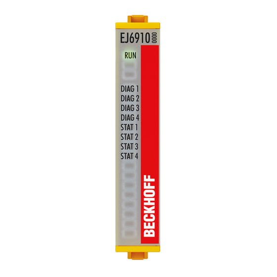
Operation 4.16 Diagnostics 4.16.1 Diagnostic LEDs The LEDs Diag 1 to Diag 4 display diagnostic information for the EJ6910. Fig. 145: EJ6910 diagnostic LEDs 4.16.1.1 LED indicators Diagnostic LEDs flashing Diag 1 Environment variables, Environment variables, (green) operating voltage and internal... - Page 100 Valid temperature difference between µC1 and µC2 exceeded not used not used General error 4.16.1.2 Flash code display Display Description flashing 400 ms ON / 400 ms OFF 1 second pause between the flash codes flickering 50 ms ON / 50 ms OFF Version: 1.7.0 EJ6910...
-
Page 101: Status Leds
Operation 4.16.2 Status LEDs The LEDs State 1 to State 4 indicate the current status of the EJ6910. Fig. 146: EJ6910 status LEDs LED Display State 1 State 2 State 3 State 4 Meaning No TwinSAFE project available on the component TwinSAFE project loaded, but not yet in RUN state TwinSAFE project loaded and in RUN state. -
Page 102: Cycle Time Of The Safety Project
Cycle time of the safety project The processing time of the EL6910/EJ6910 can be obtained from the CoE objects below. To determine the cycle time, it has to be multiplied with 1.25, because this is the factor used internally for generating a delay time before the next cycle. -
Page 103: Maintenance
Index FEA0hex: CTRL Diag Data Index Name Meaning Flags Default FEA0:09 Actual Safety Control Current processing time of the EL6910/EJ6910 when Task Execution Time logic state = 1 (RUN) cycle time = 1.25 * value (average value of 64 cycles) FEA0:0A Min Safety Control Task... -
Page 104: Decommissioning
• Housing components (polycarbonate, polyamide (PA6.6)) are suitable for plastic recycling. • Metal parts can be sent for metal recycling. • Electronic parts such as disk drives and circuit boards must be disposed of in accordance with national electronics scrap regulations. Version: 1.7.0 EJ6910... -
Page 105: Appendix
Beckhoff's branch offices and representatives Please contact your Beckhoff branch office or representative for local support and service on Beckhoff products! The addresses of Beckhoff's branch offices and representatives round the world can be found on her internet pages: http://www.beckhoff.com You will also find further documentation for Beckhoff components there. -
Page 106: Certificates
Appendix Certificates Version: 1.7.0 EJ6910... - Page 107 Fig. 13 Creating alias devices by the user....................Fig. 14 Alias device in the safety project structure .................. Fig. 15 Links to the EL6910/EJ6910 process image ................Fig. 16 Connection-specific parameters ....................Fig. 17 Selecting an alias device ......................Fig. 18 Safety parameters of the device ....................
- Page 108 Inserted data..........................Fig. 87 Visual Studio - Menu Tools / Options ..................Fig. 88 Global setting - Default Info Data....................Fig. 89 Global setting - Group Diagram Editor..................Fig. 90 Context menu - Edit TwinSAFE Group Order................Version: 1.7.0 EJ6910...
- Page 109 Fig. 102 Info data for the TwinSAFE group in the tree structure ............... Fig. 103 Enabling the info data for the EL6910 ..................Fig. 104 Info data of the EJ6910 in the tree structure................Fig. 105 Version History ..........................Fig. 106 User Administration ........................
- Page 110 Fig. 143 Typical reaction time........................Fig. 144 Worst-case reaction time ......................Fig. 145 EJ6910 diagnostic LEDs......................Fig. 146 EJ6910 status LEDs ........................101 Fig. 147 Diagnostic object: FSLOGIC Status (F100hex) in the process image of the TwinSAFE compo- nent.............................. 102 Fig.
Need help?
Do you have a question about the EJ6910 and is the answer not in the manual?
Questions and answers