Subscribe to Our Youtube Channel
Summary of Contents for Beckhoff EM2042
- Page 1 Documentation EM2042 Sixteen Channel Digital Output Module with D-Sub Connector Version: 2.1.0 Date: 2019-03-11...
-
Page 3: Table Of Contents
3 Mounting and wiring.......................... 10 Instructions for ESD protection ...................... 10 Recommended mounting rails ...................... 10 Mounting and demounting - terminals with front unlocking ............. 11 Dimensions ............................ 12 Positioning of passive Terminals ..................... 13 Connection ............................ 14 4 Appendix .............................. 16 Support and Service ........................ 16 EM2042 Version: 2.1.0... - Page 4 Table of contents Version: 2.1.0 EM2042...
-
Page 5: Foreword
The TwinCAT Technology is covered, including but not limited to the following patent applications and patents: EP0851348, US6167425 with corresponding applications or registrations in various other countries. ® EtherCAT is registered trademark and patented technology, licensed by Beckhoff Automation GmbH, Germany. Copyright © Beckhoff Automation GmbH & Co. KG, Germany. -
Page 6: Safety Instructions
All the components are supplied in particular hardware and software configurations appropriate for the application. Modifications to hardware or software configurations other than those described in the documentation are not permitted, and nullify the liability of Beckhoff Automation GmbH & Co. KG. Personnel qualification This description is only intended for trained specialists in control, automation and drive engineering who are familiar with the applicable national standards. -
Page 7: Documentation Issue Status
FF - firmware version HH - hardware version Example with ser. no.: 31 09 00 01: 31 - week of production 31 09 - year of production 2009 00 - firmware version 00 01 - hardware version 01 EM2042 Version: 2.1.0... -
Page 8: Product Overview
Product overview Product overview Technical data Technical data EM2042 Number of outputs Rated load voltage 24 V (-15 %/+20 %) Load type ohmic, inductive, lamp load Output current max. 0,5 A each channel, individually short-circuit proof, total current max. 4 A Short circuit current 0.6 A…1.0 A... -
Page 9: Introduction
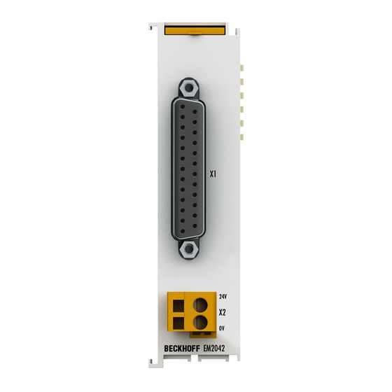
Introduction Fig. 1: EM2042 The EM2042 Terminal Module combines 16 digital outputs in a Sub-D plug connector in a compact design. The binary control signals are transferred (electrically isolated) to the actuators at the process level. Like the standard Bus Terminals, the terminal modules are integrated in the I/O system. -
Page 10: Mounting And Wiring
• Each assembly must be terminated at the right hand end with an EL9011 or EL9012 bus end cap, to en- sure the protection class and ESD protection. Fig. 2: Spring contacts of the Beckhoff I/O components Recommended mounting rails Terminal Modules und EtherCAT Modules of KMxxxx and EMxxxx series, same as the terminals of the EL66xx and EL67xx series can be snapped onto the following recommended mounting rails: •... -
Page 11: Mounting And Demounting - Terminals With Front Unlocking
• Attach the cables. Demounting • Remove all the cables. • Lever the unlatching hook back with thumb and forefinger (3). An internal mechanism pulls the two latching lugs (3a) from the top hat rail back into the terminal module. EM2042 Version: 2.1.0... -
Page 12: Dimensions
Mounting and wiring • Pull (4) the terminal module away from the mounting surface. Avoid canting of the module; you should stabilize the module with the other hand, if required. Dimensions Fig. 3: EM2042 Dimensions Version: 2.1.0 EM2042... -
Page 13: Positioning Of Passive Terminals
The passive terminals have no current consump- tion out of the E-Bus. To ensure an optimal data transfer, you must not directly string together more than 2 passive termi- nals! Examples for positioning of passive terminals (highlighted) Fig. 4: Correct positioning Fig. 5: Incorrect positioning EM2042 Version: 2.1.0... -
Page 14: Connection
Fig. 6: EM2042 X1: Signal connection, digital outputs, D-Sub 25 The EM2042 digital output module transmits the binary control signals from the automation unit on to the actuators at the process level. The 16 outputs deliver load currents of up to 0.5 A, although the total current from all the outputs must not exceed 4 A. -
Page 15: Fig. 7 D-Sub 25 - Signal Connection, Digital Outputs
Mounting and wiring Fig. 7: D-Sub 25 - signal connection, digital outputs X2: Connection of the voltage supply for the outputs Name Description 24 V Supply voltage 24 V Supply voltage 0 V EM2042 Version: 2.1.0... -
Page 16: Appendix
Beckhoff's branch offices and representatives Please contact your Beckhoff branch office or representative for local support and service on Beckhoff products! The addresses of Beckhoff's branch offices and representatives round the world can be found on her internet pages: http://www.beckhoff.com You will also find further documentation for Beckhoff components there. - Page 17 Table of figures Table of figures Fig. 1 EM2042 ............................Fig. 2 Spring contacts of the Beckhoff I/O components................. Fig. 3 EM2042 Dimensions........................Fig. 4 Correct positioning........................Fig. 5 Incorrect positioning........................Fig. 6 EM2042 ............................Fig. 7 D-Sub 25 - signal connection, digital outputs ................


Need help?
Do you have a question about the EM2042 and is the answer not in the manual?
Questions and answers