Table of Contents
Advertisement
Quick Links
Advertisement
Table of Contents

Related Manuals for Beckhoff EP9576-1032


Summary of Contents for Beckhoff EP9576-1032
- Page 1 Documentation | EN EP9576-1032 Brake chopper box 2024-05-17 | Version: 1.1...
-
Page 3: Table Of Contents
Objects for parameterization .................... 32 6.2.2 Objects for information and diagnostics ................ 33 6.2.3 Standard objects ...................... 34 6.2.4 PDO Mapping and PDO Assignment ................ 36 6.2.5 Sync manager objects...................... 38 7 Appendix .............................. 40 General operating conditions ...................... 40 EP9576-1032 Version: 1.1... - Page 4 Version identification of EtherCAT devices .................. 42 7.3.1 General notes on marking.................... 42 7.3.2 Version identification of IP67 modules ................ 43 7.3.3 Beckhoff Identification Code (BIC) ................... 44 7.3.4 Electronic access to the BIC (eBIC)................. 46 Support and Service........................ 48 Version: 1.1 EP9576-1032...
-
Page 5: Foreword
, XTS and XPlanar are registered trademarks of and licensed by Beckhoff Automation GmbH. Other designations used in this publication may be trademarks whose use by third parties for their own purposes could violate the rights of the owners. Patent Pending... -
Page 6: Safety Instructions
All the components are supplied in particular hardware and software configurations appropriate for the application. Modifications to hardware or software configurations other than those described in the documentation are not permitted, and nullify the liability of Beckhoff Automation GmbH & Co. KG. Personnel qualification This description is only intended for trained specialists in control, automation and drive engineering who are familiar with the applicable national standards. -
Page 7: Documentation Issue Status
YY - year of production 10 - year of production 2010 FF - firmware version 02 - firmware version 02 HH - hardware version 01 - hardware version 01 Further information on this topic: Version identification of EtherCAT devices [} 42]. EP9576-1032 Version: 1.1... -
Page 8: Ethercat Box - Introduction
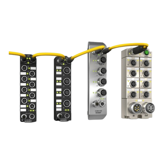
• digital outputs with 0.5 or 2 A output current • analog inputs and outputs with 16 bit resolution • Thermocouple and RTD inputs • Stepper motor modules XFC (eXtreme Fast Control Technology) modules, including inputs with time stamp, are also available. Version: 1.1 EP9576-1032... - Page 9 Fig. 3: EtherCAT Box with M12 connections for sensors/actuators Basic EtherCAT documentation You will find a detailed description of the EtherCAT system in the Basic System Documentation for EtherCAT, which is available for download from our website (www.beckhoff.com) under Downloads. EP9576-1032 Version: 1.1...
-
Page 10: Product Overview
The EP9576-1032 EtherCAT Box contains an integrated brake resistor for the dissipation of drive-related overvoltages. The brake resistor converts excess energy, generated when braking, motors into heat. The EP9576-1032 can be used in conjunction with the EP70xx stepper motor modules, the EP7211 servo motor modules or the EP7342 DC motor output stage. -
Page 11: Block Diagram
Product overview Block diagram The block diagram shows the distribution of the voltages U and U inside the EP9576-1032. Capacity Brake resistor Logic Chopper P,sum S,sum Technical data All values are typical values over the entire temperature range, unless stated otherwise. -
Page 12: Scope Of Supply
Scope of supply Make sure that the following components are included in the scope of delivery: • 1x EP9576-1032 • 2x protective cap for EtherCAT socket, M8, green (pre-assembled) • 1x Protective cap for supply voltage output, 7/8”, black (pre-fitted) •... -
Page 13: Process Image
The measured value [} 27] of the voltage U . Unit: mV Resistor Current The measured value [} 27] of the current through the brake resistor. Unit: mA. Duty Cycle The current mark-to-space ratio of the chopper [} 24]. Unit: %. EP9576-1032 Version: 1.1... - Page 14 Product overview Optional process data objects You can add a further process data object [} 25] to the process image: I2T load factor The current temperature of the brake resistor. Unit: °C. Version: 1.1 EP9576-1032...
-
Page 15: Technology
Product overview Technology The following figure shows an example of a voltage curve that illustrates the operation of EP9576-1032. The upper diagram shows the voltage U in mV, the lower diagram shows the activity of the chopper. In this example, a motor output stage is supplied with U = 24 V. -
Page 16: Mounting And Connections
• Allow the device to cool down after operation before touching it. • When installing, ensure that neighboring components are not damaged by heat. 4.1.1 Dimensions 60.5 26.5 Ø 4.5 All dimensions are given in millimeters. The drawing is not true to scale. Version: 1.1 EP9576-1032... -
Page 17: Fixing
The Fixing [} 17] also serve as connections for the functional earth (FE). Make sure that the box is earthed with low impedance via both fastening screws. You can achieve this, for example, by mounting the box on a grounded machine bed. EP9576-1032 Version: 1.1... -
Page 18: Connections
GND for U GND for U Functional earth Supply voltage 24 V Supply voltage 0...72 V Ground the core "FE" at the other end of the cable. The pin "FE" is directly connected to the connections for the functional earth [} 17]. Version: 1.1 EP9576-1032... - Page 19 Voltage drop on the supply line 1.5 mm² 2.5 mm² 16 A Vert. Faktor: 0,45 cm / V Vert. Faktor: 0,4 12 A 16 A Vert. Faktor: 0,45 cm / V Vert. Faktor: 12 A Cable length (m) Cable length (m) EP9576-1032 Version: 1.1...
-
Page 20: Ethercat
For standardization, the core colors of the ZB9030, ZB9032 and ZK1090-3xxx-xxxx cables have been changed to the EN61918 core colors: yellow, orange, white, blue. So there are different color codes in circulation. The electrical properties of the cables have been retained when the core colors were changed. Version: 1.1 EP9576-1032... - Page 21 (CAT5) according to EN 50173 or ISO/IEC 11801 should be used. EtherCAT uses four wires for signal transmission. Thanks to automatic line detection ("Auto MDI-X"), both symmetrical (1:1) or cross-over cables can be used between Beckhoff EtherCAT. Detailed recommendations for the cabling of EtherCAT devices EP9576-1032...
-
Page 22: Disposal
Products marked with a crossed-out wheeled bin shall not be discarded with the normal waste stream. The device is considered as waste electrical and electronic equipment. The national regulations for the disposal of waste electrical and electronic equipment must be observed. Version: 1.1 EP9576-1032... -
Page 23: Commissioning And Configuration
1. In the Solution Explorer: Double-click EP9576-1032. 2. Click on the "CoE - Online" tab. ð You will see the CoE directory of the EP9576-1032. Here you can check and change parameter values. Resetting parameters to factory settings If you do not know whether parameters have already been changed by the present EP9576-1032, you can reset all parameters to the factory settings [} 29]. -
Page 24: Chopper
Hysteresis voltage for switching off the Chopper. UINT32 RW 1000 voltage Unit: mV. The following diagram shows the influence of the parameters on an exemplary curve of the voltage U 8000:11 "Chopper threshold overvoltage" 8000:13 "Chopper hysteresis voltage" Time Version: 1.1 EP9576-1032... -
Page 25: Measured Values
You can display the temperature of the braking resistor in the process data. To do this, activate the process data object 0x1A01. Procedure in TwinCAT 3: 1. Double-click on EP9576-1032 in Solution Explorer. 2. Select the "Process data" tab. 3. In the "Sync Manager" field, click on "Inputs". - Page 26 Commissioning and configuration 5.4.1.2 Internal temperature The current internal temperature is located in the CoE parameter A000:11 "Temperature". The internal temperature is purely informative. It is not monitored by any protective function [} 28]. Version: 1.1 EP9576-1032...
-
Page 27: Current And Voltage
Enables the measured value filter [} 27]. 8000:1A Filter Settings Measured value filter type: UINT16 RW 0: FIR 50 Hz 1: FIR 60 Hz 2: IIR1 3: IIR2 4: IIR3 5: IIR4 6: IIR5 7: IIR6 8: IIR7 9: IIR8 EP9576-1032 Version: 1.1... -
Page 28: Protective Functions
15.5 A. The bit "Overcurrent Protection" in the process data [} 13] is set to TRUE. The chopper remains disabled until you apply a positive edge to the parameter 8000:03 "Overcurrent Protection Reset": set the parameter from FALSE to TRUE. Version: 1.1 EP9576-1032... -
Page 29: Restoring The Delivery State
Fig. 8: Entering a restore value in the Set Value dialog Alternative restore value In some older terminals / boxes the backup objects can be switched with an alternative restore value: Decimal value: 1819238756 Hexadecimal value: 0x6C6F6164 An incorrect entry for the restore value has no effect. EP9576-1032 Version: 1.1... -
Page 30: Decommissioning
Commissioning and configuration Decommissioning WARNING Risk of electric shock! Bring the bus system into a safe, de-energized state before starting disassembly of the devices! Version: 1.1 EP9576-1032... -
Page 31: Coe Parameters
BCT Inputs [} 37] 6001 BCT Load Factor [} 37] 8000 BCT Settings [} 32] 800F BCT Vendor data [} 33] A000 BCT Diag data [} 33] B000 BCT Command [} 35] F000 Modular Device Profile [} 35] F008 Code word [} 35] F081 Download revision [} 35] EP9576-1032 Version: 1.1... -
Page 32: Object Description
The bit "I2T error" is set to TRUE. Unit: °C. 8000:1A Filter Settings Measured value filter type: UINT16 RW 0: FIR 50 Hz 1: FIR 60 Hz 2: IIR1 3: IIR2 4: IIR3 5: IIR4 6: IIR5 7: IIR6 8: IIR7 9: IIR8 Version: 1.1 EP9576-1032... -
Page 33: Objects For Information And Diagnostics
UINT16 RW Vendor calibration: Offset value for voltage gain measurement [} 27]. Index A000: BCT Diag data Index Name Description Data Flags Default (hex) type A000:0 BCT Diag data UINT8 0x11 A000:11 Temperature UINT8 Internal temperature [} 26]. Unit: °C. EP9576-1032 Version: 1.1... -
Page 34: Standard Objects
1018:0 Identity Information for identifying the slave UINT8 0x04 (4dec) 1018:01 Vendor ID Vendor identifier (2: Beckhoff Automation) UINT32 RO 1018:02 Product code Product code UINT32 RO 2568405 1018:03 Revision Bit 0...15: Index number of the product version UINT32 RO 0...15:... - Page 35 Index F008: Code word Index Name Meaning Data Flags Default type F008:0 Code word UINT32 RW Index F081: Download revision Index Name Meaning Data Flags Default type F081:0 Download revision UINT8 0x01 F081:01 Revision number UINT32 RW EP9576-1032 Version: 1.1...
-
Page 36: Pdo Mapping And Pdo Assignment
1A01:01 SubIndex 001 1. PDO Mapping entry (object 0x6001 (BCT UINT32 RO 0x6001:01, 8 Load Factor), entry 0x01 (I2T load factor)) Index 1C12: RxPDO assign Index Name Meaning Data Flags Default type 1C12:0 RxPDO assign PDO Assign Outputs UINT8 Version: 1.1 EP9576-1032... - Page 37 6000:11 DC link voltage UINT32 RO 6000:13 Resistor Current INT32 6000:14 Duty Cycle UINT8 Index 6001: BCT Load Factor Index Name Meaning Data Flags Default type 6001:0 BCT Load Factor UINT8 6001:01 I2T load factor UINT8 EP9576-1032 Version: 1.1...
-
Page 38: Sync Manager Objects
1C00:02 SubIndex 002 Sync-Manager Type Channel 2: Mailbox Read UINT8 0x02 1C00:03 SubIndex 003 Sync-Manager Type Channel 3: Process Data UINT8 0x03 Write (Outputs) 1C00:04 SubIndex 004 Sync-Manager Type Channel 4: Process Data UINT8 0x04 Read (Inputs) Version: 1.1 EP9576-1032... - Page 39 (in ns, only DC mode) 1C33:0B SM event missed as 1C32:11 UINT16 RO counter 1C33:0 Cycle exceeded as 1C32:12 UINT16 RO counter 1C33:0 Shift too short as 1C32:13 UINT16 RO counter 1C33:20 Sync error as 1C32:32 BOOL EP9576-1032 Version: 1.1...
-
Page 40: Appendix
(ph value > 12) unstable > 40 °C Acetic acid unstable Argon (technically pure) stable • resistant: Lifetime several months • non inherently resistant: Lifetime several weeks • not resistant: Lifetime several hours resp. early decomposition Version: 1.1 EP9576-1032... -
Page 41: Accessories
ZB8801-0000 Torque wrench for plugs, 0.4…1.0 Nm ZB8801-0001 Torque cable key for M8 / wrench size 9 for ZB8801-0000 Further accessories Further accessories can be found in the price list for fieldbus components from Beckhoff and online at https://www.beckhoff.com. EP9576-1032 Version: 1.1... -
Page 42: Version Identification Of Ethercat Devices
Associated and synonymous with each revision there is usually a description (ESI, EtherCAT Slave Information) in the form of an XML file, which is available for download from the Beckhoff web site. From 2014/01 the revision is shown on the outside of the IP20 terminals, see Fig. “EL2872 with revision 0022 and serial number 01200815”. -
Page 43: Version Identification Of Ip67 Modules
Version identification of IP67 modules The serial number/ data code for Beckhoff IO devices is usually the 8-digit number printed on the device or on a sticker. The serial number indicates the configuration in delivery state and therefore refers to a whole production batch, without distinguishing the individual modules of a batch. -
Page 44: Beckhoff Identification Code (Bic)
7.3.3 Beckhoff Identification Code (BIC) The Beckhoff Identification Code (BIC) is increasingly being applied to Beckhoff products to uniquely identify the product. The BIC is represented as a Data Matrix Code (DMC, code scheme ECC200), the content is based on the ANSI standard MH10.8.2-2016. - Page 45 Fig. 11: Example DMC 1P072222SBTNk4p562d71KEL1809 Q1 51S678294 An important component of the BIC is the Beckhoff Traceability Number (BTN, position 2). The BTN is a unique serial number consisting of eight characters that will replace all other serial number systems at Beckhoff in the long term (e.g.
-
Page 46: Electronic Access To The Bic (Ebic)
Electronic access to the BIC (eBIC) Electronic BIC (eBIC) The Beckhoff Identification Code (BIC) is applied to the outside of Beckhoff products in a visible place. If possible, it should also be electronically readable. The interface that the product can be electronically addressed by is crucial for the electronic readout. - Page 47 • The following auxiliary functions are available for processing the BIC/BTN data in the PLC in Tc2_Utilities as of TwinCAT 3.1 build 4024.24 ◦ F_SplitBIC: The function splits the Beckhoff Identification Code (BIC) sBICValue into its components using known identifiers and returns the recognized substrings in the ST_SplittedBIC structure as a return value ◦...
-
Page 48: Support And Service
Please contact your Beckhoff branch office or representative for local support and service on Beckhoff products! The addresses of Beckhoff's branch offices and representatives round the world can be found on her internet pages: www.beckhoff.com You will also find further documentation for Beckhoff components there. - Page 50 More Information: www.beckhoff.com/ep9576-1032 Beckhoff Automation GmbH & Co. KG Hülshorstweg 20 33415 Verl Germany Phone: +49 5246 9630 info@beckhoff.com www.beckhoff.com...
Need help?
Do you have a question about the EP9576-1032 and is the answer not in the manual?
Questions and answers