
Related Manuals for Beckhoff EP1 Series


Summary of Contents for Beckhoff EP1 Series
- Page 1 Documentation EP1xxx EtherCAT Box Modules with digital inputs Version: 2.5.0 Date: 2017-05-19...
-
Page 3: Table Of Contents
Table of contents Table of contents 1 Foreword .............................. 5 Notes on the documentation...................... 5 Safety instructions .......................... 6 Documentation issue status...................... 7 2 Product overview............................ 9 EtherCAT Box - Introduction...................... 9 EP1xxx Module overview...................... 11 EP1008, EP1018 .......................... 12 2.3.1 EP1008, EP1018 - Introduction .................. 12 2.3.2 EP1008, EP1018 - Technical Data .................. 14 2.3.3... - Page 4 Table of contents Power supply .......................... 49 3.3.1 Power Connection...................... 49 3.3.2 Status LEDs for power supply.................. 52 3.3.3 Power cable conductor losses M8 ................... 53 UL Requirements.......................... 54 ATEX notes........................... 55 3.5.1 ATEX - Special conditions .................... 55 3.5.2 BG2000-0000 - EtherCAT Box protection enclosure ............ 56 3.5.3 ATEX Documentation ...................... 57 Signal connection .........................
-
Page 5: Foreword
The TwinCAT Technology is covered, including but not limited to the following patent applications and patents: EP0851348, US6167425 with corresponding applications or registrations in various other countries. ® EtherCAT is registered trademark and patented technology, licensed by Beckhoff Automation GmbH, Germany Copyright © Beckhoff Automation GmbH & Co. KG, Germany. -
Page 6: Safety Instructions
All the components are supplied in particular hardware and software configurations appropriate for the application. Modifications to hardware or software configurations other than those described in the documentation are not permitted, and nullify the liability of Beckhoff Automation GmbH & Co. KG. Personnel qualification This description is only intended for trained specialists in control, automation and drive engineering who are familiar with the applicable national standards. -
Page 7: Documentation Issue Status
Foreword Documentation issue status Version Modifications 2.5.0 • EP1816-3008 added 2.4.1 • EP1111-0000 – technical data updated 2.4.0 • Nut torques for connectors updated 2.3.0 • Torque wrench diagram updated • Power connection updated 2.2.0 • EP1008-0022 added • EP1819-0021 added •... - Page 8 Foreword WW - week of production (calendar week) YY - year of production FF - firmware version HH - hardware version Example with D no. 29 10 02 01: 29 - week of production 29 10 - year of production 2010 02 - firmware version 02 01 - hardware version 01 Version: 2.5.0...
-
Page 9: Product Overview
Product overview Product overview EtherCAT Box - Introduction The EtherCAT system has been extended with EtherCAT Box modules with protection class IP 67. Through the integrated EtherCAT interface the modules can be connected directly to an EtherCAT network without an additional Coupler Box. The high-performance of EtherCAT is thus maintained into each module. The extremely low dimensions of only 126 x 30 x 26.5 mm (h x w x d) are identical to those of the Fieldbus Box extension modules. -
Page 10: Fig. 2 Ethercat Box With M8 Connections For Sensors/Actuators
EtherCAT, which is available for download from our website (www.beckhoff.com) Note under Downloads. XML files You will find XML files (XML Device Description Files) for Beckhoff EtherCAT modules on our website (www.beckhoff.com) under Downloads, in the Configuration Files area. Note Version: 2.5.0... -
Page 11: Ep1Xxx Module Overview
Product overview EP1xxx Module overview Digital input modules Module Signal connection Number of inputs Filter Comment 8 x M8 3.0 ms EP1008-0001 [} 12] 4 x M12 3.0 ms EP1008-0002 [} 12] 8 x M12 3.0 ms EP1008-0022 [} 12] 8 x M8 10 µs EP1018-0001 [} 12] 4 x M12 10 µs EP1018-0002 [} 12]... -
Page 12: Ep1008, Ep1018
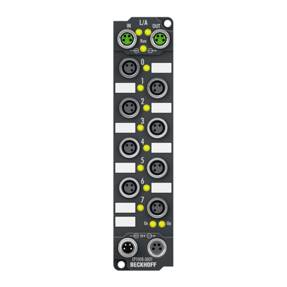
Product overview EP1008, EP1018 2.3.1 EP1008, EP1018 - Introduction Fig. 4: EP1008-0001, EP1018-0001 Fig. 5: EP1008-0002, EP1018-0002 Version: 2.5.0 EP1xxx... -
Page 13: Fig. 6 Ep1008-0022
Product overview Fig. 6: EP1008-0022 8 digital inputs, 24 V The EP1008 and EP1018 EtherCAT Box modules with digital inputs acquire binary control signals from the process level, and transfer them, electrically isolated, to the controller. The status of the signal is displayed by light emitting diodes; the signal connection is made optionally through M8 connectors (EP1008-0001, EP1018-0001) or M12 connectors (EP1008-0002, EP1018-0002, EP1008-0022). -
Page 14: Ep1008, Ep1018 - Technical Data
Product overview 2.3.2 EP1008, EP1018 - Technical Data Technical data EP1008-0001 EP1008-0002 EP1008-0022 EP1018-0001 EP1018-0002 Fieldbus EtherCAT Fieldbus connection 2 x M8 socket (green) Number of inputs Input connections Nominal input voltage 24 V (-15%/+20%) Input filter 3,0 ms 3,0 ms 3,0 ms 10 µs 10 µs "0"... -
Page 15: Ep1008-0001 - Process Image
Product overview 2.3.3 EP1008-0001 - Process image Channel 1 to Channel 8 You will find the 8 digital inputs to the module (here using the EP1008-0001 as an example) under Channel 1 to Channel 8. Fig. 7: EP1008-0001, Process image EP1xxx Version: 2.5.0... -
Page 16: Ep1098 - Introduction
Product overview EP1098-0001 2.4.1 EP1098 - Introduction Fig. 8: EP1098-0001 8 digital inputs, 24 V , negative switching The EP1098 EtherCAT Box modules with digital inputs acquire binary control signals from the process level, and transfer them, electrically isolated, to the controller. The status of the signal is displayed by light emitting diodes. -
Page 17: Ep1098 - Technical Data
Product overview 2.4.2 EP1098 - Technical Data Technical data EP1098-0001 Fieldbus EtherCAT Fieldbus connection 2 x M8 socket (green) Number of inputs 8 (negative switching) Input connections Nominal input voltage 24 V (-15%/+20%) Input filter 10 µs "0" signal voltage 11…30 V "1" signal voltage 0…7 V Input current typically 2.5 mA (EN 61131-2, Type 3) -
Page 18: Ep1098-0001 - Process Image
Product overview 2.4.3 EP1098-0001 - Process image Channel 1 to Channel 8 You will find the 8 digital inputs to the module (here using the EP1098-0001 as an example) under Channel 1 to Channel 8. Fig. 9: EP1098-0001, Process image Version: 2.5.0 EP1xxx... -
Page 19: Ep1111-0000 - Introduction
Product overview EP1111-0000 2.5.1 EP1111-0000 - Introduction Fig. 10: EP1111-0000 EtherCAT Box with ID switch The EP1111-0000 EtherCAT Box has three decimal ID switches, with which a group of EtherCAT components can be assigned an ID. This group can be present in any position in the EtherCAT network, as a result of which variable topologies can be realized in a simple manner. -
Page 20: Ep1111-0000 - Technical Data
Product overview 2.5.2 EP1111-0000 - Technical Data Technical data EP1111-0000 Fieldbus EtherCAT Fieldbus connection 2 x M8 socket (green) Task within EtherCAT system identification of any EtherCAT group in the EtherCAT network Number of ID switches Positions per ID switch Number of different IDs Module electronic supply derived from control voltage Us... -
Page 21: Ep1258-000X
You will find more information about the distributed clocks system in the Distributed Clocks System Description, which is available under Download at our Internet site (http://www.beckhoff.com). Quick links... -
Page 22: Ep1258 - Technical Data
Product overview UL Requirements for UL approved modules ATEX - Special conditions for ATEX approved modules 2.6.2 EP1258 - Technical Data Technical data EP1258-0001 EP1258-0002 Fieldbus EtherCAT Fieldbus connection 2 x M8 socket (green) Number of inputs Input connections Nominal input voltage 24 V (-15%/+20%) Input filter... -
Page 23: Ep1258-0001 - Process Image
Product overview 2.6.3 EP1258-0001 - Process image Channel 1 to Channel 8 Fig. 13: EP1258-0001, Process image You will find the 8 digital inputs to the module (here using the EP1258-0001 as an example) under Channel 1 to Channel 8. EP1xxx Version: 2.5.0... -
Page 24: Ep1809, Ep1819
Product overview EP1809, EP1819 2.7.1 EP1809-0021, EP1819-0021 - Introduction Fig. 14: EP1809-0021, EP1819-0021 16 digital inputs, 24 V The EtherCAT modules EP1809-0021 and EP1819-0021 with digital inputs acquires the binary control signals from the process level and transmits them, in an electrically isolated form, to the controller. The state of the signals is indicated by light emitting diodes. -
Page 25: Ep1809-0022, Ep1819-0022 - Introduction
Product overview 2.7.2 EP1809-0022, EP1819-0022 - Introduction Fig. 15: EP1809-0022, EP1819-0022 16 digital inputs 24 V The EP1809-0022 and EP1819-0022 modules with digital inputs acquire the binary control signals from the process level and transmit them, in an electrically isolated form, to the controller. The state of the signals is indicated by light emitting diodes. -
Page 26: Ep1809, Ep1819 - Technical Data
Product overview 2.7.3 EP1809, EP1819 - Technical data Technical data EP1809-0021 EP1809-0022 EP1819-0021 EP1819-0022 Fieldbus EtherCAT Fieldbus connection 2 x M8 socket (green) Number of inputs Input connections Nominal input voltage 24 V (-15%/+20%) Input filter 3 ms 3 ms 10 µs 10 µs "0"... -
Page 27: Ep1809-0021 - Process Image
Product overview 2.7.4 EP1809-0021 - Process image Channel 1 to Channel 16 You will find the 16 digital inputs to the module (here using the EP1809-0021 as an example) under Channel 1 to Channel 16. Fig. 16: EP1809-0021, Process image EP1xxx Version: 2.5.0... -
Page 28: Ep1816-0008 - Introduction
Product overview EP1816-0008 2.8.1 EP1816-0008 - Introduction Fig. 17: EP1816-0008 16 digital inputs, 24 V The EP1816-0008 EtherCAT Box with digital inputs acquires binary control signals from the process level and transfers them, with electrical isolation, to the controller. The signal status is indicated by light emitting diodes;... -
Page 29: Ep1816-0008 - Technical Data
Product overview 2.8.2 EP1816-0008 - Technical Data Technical data EP1816-0008 Fieldbus EtherCAT Fieldbus connection 2 x M8 socket (green) Number of inputs 25 pin SUB-D socket Input connections [} 59] Nominal input voltage 24 V (-15%/+20%) Input filter 10 µs "0" signal voltage -3...+5 V (EN 61131-2, Type 3) "1"... -
Page 30: Ep1816-0008 - Process Image
Product overview LED display Display Meaning STATUS 1-8 Green illuminated A signal (24 V) is present at a least one of the inputs for channels 1 to 8 STATUS 9-16 Green illuminated A signal (24 V) is present at a least one of the inputs for channels 9 to 16 The power supply voltage, Us, is not present Green illuminated... -
Page 31: Ep1816-3008 - Introduction
Product overview EP1816-3008 2.9.1 EP1816-3008 - Introduction Fig. 21: EP1816-3008 16 digital inputs 24 V , 2 x 3G accelerometers The EP1816-3008 EtherCAT Box with digital inputs acquires binary control signals from the process level and transfers them, with electrical isolation, to the controller. The signal status is indicated by light emitting diodes;... -
Page 32: Ep1816-3008 - Technical Data
Product overview 2.9.2 EP1816-3008 - Technical data Technical data EP1816-3008 Fieldbus EtherCAT Fieldbus connection 2 x M8 socket (green) Number of inputs 25 pin SUB-D socket Input connections [} 60] Rated input voltage 24 V (-15%/+20%) Input filter 10 µs Signal voltage "0" -3...+5 V (EN 61131-2, type 3) Signal voltage "1"... -
Page 33: Ep1816-3008 - Process Image
Product overview 2.9.3 EP1816-3008 - Process image DIG Inputs Channel 1 and 2 Fig. 22: EP1816-3008, process image, DIG inputs channels 1 and 2 The 16 digital inputs of the module can be found under DIG Inputs Channel n. AI Inputs Channel 1 to 6 Fig. 23: EP1816-3008 - AI inputs channels 1 to 6 The data for the two accelerometers can be found under AI inputs Channel •... -
Page 34: Fig. 24 Ep1816-3008 Dig Inputs Device
Product overview AI Inputs Channel 1 value: sensor 2, axis +Y AI Inputs Channel 2 value: sensor 2, axis -X AI Inputs Channel 3 value: sensor 2, axis -Z DIG Inputs Device Fig. 24: EP1816-3008 DIG Inputs Device 16 bit status bit of the module Version: 2.5.0 EP1xxx... -
Page 35: Accelerometers
Product overview 2.9.4 Accelerometers 2 x 3G accelerometers The EP1816-3008 EtherCAT Box features 2 3-axis accelerometers. They are fitted on the underside the PCB at 90° angles. Fig. 25: Location of the accelerometers The image shows a top view and a side view of the EtherCAT Box. It shows the location of the accelerometers within the Box. -
Page 36: Acceleration Measurement
Product overview 2.9.5 Acceleration measurement Resolution and display By default the data from the accelerometers, in each case X, Y and Z axis values, are displayed as RAW data, i.e. directly in the form in which they are transferred from the sensors. Fig. 26: CoE object 0x8080:1D Alternatively, the data can be converted to 1mG / LSB. -
Page 37: Update Frequency
Product overview Example for acceleration value display in TwinCAT ScopeView 2 Fig. 28: EP1816-3008, movement of the box in the axes, resulting acceleration values Color Meaning Blue sensor 1, Z axis sensor 1, X axis Green Sensor 1, Y axis 2.9.6 Update frequency Fig. 29: Update frequency The update frequency of the sensor data is set via CoE object 0x8080:0D. -
Page 38: Angle Measurement
Product overview 2.9.7 Angle measurement The angle relative to gravity can be calculated directly in the EP1816-3008 (CoE 0x8080:1D). However, the complex trigonometric calculations would have undue impact on the cycle time of the Box, so that in this mode the angle resolution is limited to 1°. In cases where higher resolution and accuracy is required, the calculations should be executed on a PC. -
Page 39: Fig. 31 Signal Noise In Detail
Product overview Fig. 31: Signal noise in detail Color Meaning Angle measured with 1024-step encoder / 4-way analysis for reference Green Angle trigonometrically calculated on a PC, without noise suppression blue Fast algorithm yellow Arithmetic mean (1000 sliding values) Direct measurement in the EP1816-3008 For direct measurements CoE object 0x8080:1D Presentation must be set to Horizontal Off-Axis Angle. -
Page 40: Fig. 33 Red = Angle Values From Ep1816-3008, Green = After Arithmetic Mean Calculation On The Pc
Product overview The angle is displayed with a resolution of 1 degree. Since the value is still noisy, filtering on the PC is recommended. Fig. 33: red = angle values from EP1816-3008, green = after arithmetic mean calculation on the PC Reference directions •... - Page 41 To download the sample program from this documentation please click on the following link: (http:// infosys.beckhoff.com/content/1033/ep1xxx/Resources/zip/3626380299.zip) EP1xxx Version: 2.5.0...
-
Page 42: Mounting And Cabling
Mounting and cabling Mounting and cabling Mounting 3.1.1 Dimensions Fig. 34: Dimensions of the EtherCAT Box Modules All dimensions are given in millimeters. Housing properties EtherCAT Box lean body wide body Housing material PA6 (polyamide) Casting compound Polyurethane Mounting two fastening holes Ø 3 mm for M3 two fastening holes Ø 3 mm for M3 two fastening holes Ø 4,5 mm for M4 Metal parts... -
Page 43: Fixing
Mounting and cabling 3.1.2 Fixing Note or pointer While mounting the modules, protect all connectors, especially the IP-Link, against contam- ination! Only with connected cables or plugs the protection class IP67 is guaranteed! Un- Note used connectors have to be protected with the right plugs! See for plug sets in the cata- logue. -
Page 44: Nut Torque For Connectors
Mounting and cabling 3.1.3 Nut torque for connectors M8 connectors It is recommended to pull the M8 connectors tight with a nut torque of 0.4 Nm. When using the torque control screwdriver ZB8800 is also a max. torque of 0.5 Nm permissible. Fig. 36: EtherCAT Box with M8 connectors M12 connectors It is recommended to pull the M12 connectors tight with a nut torque of 0.6 Nm. -
Page 45: Additional Checks
We recommend fastening the 7/8" plug connectors with a torque of 1.5 Nm. Fig. 38: 7/8" plug connectors Torque socket wrenches Fig. 39: ZB8801 torque socket wrench Ensure the right torque Use the torque socket wrenches available by Beckhoff to pull the connectors tight (ZB8800, ZB8801-0000)! Note 3.1.4 Additional checks... -
Page 46: Ethercat
Mounting and cabling EtherCAT 3.2.1 EtherCAT connection For the incoming and ongoing EtherCAT connection, • the EtherCAT Box (EPxxxx) has two M8 sockets, marked in green • the Coupler Box (FBB-x110) has two M12 sockets Fig. 40: EtherCAT Box: M8 (30 mm housing) Fig. 41: EtherCAT Box: M8 60 mm housing (EP9214 for example ) Version: 2.5.0 EP1xxx... -
Page 47: Fig. 42 Coupler Box: M12
M8 connectors were changed to the colors of EN61918 (yel- low, orange, white, blue).So different color coding exists. But the electrical properties are absolutely identical. EtherCAT connectors The following connectors can be supplied for use in Beckhoff EtherCAT systems. EP1xxx Version: 2.5.0... -
Page 48: Ethercat - Fieldbus Leds
Status of the EtherCAT module is operational EtherCAT statuses The various statuses in which an EtherCAT module may be found are described in the Ba- sic System Documentation for EtherCAT, which is available for download from our website Note (www.beckhoff.com) under Downloads. Version: 2.5.0 EP1xxx... -
Page 49: Power Supply
Mounting and cabling Power supply 3.3.1 Power Connection The feeding and forwarding of supply voltages is done via two M8 connectors at the bottom end of the modules: • IN: left M8 connector for feeding the supply voltages • OUT: right M8 connector for forwarding the supply voltages Fig. 44: EtherCAT Box, Connectors for power supply Fig. 45: Pin assignment M8, Power In and Power Out Table 1: PIN assignment... - Page 50 Mounting and cabling Auxiliary voltage Up 24 V The Auxiliary voltage Up supplies the digital outputs; it can be brought in separately. If the load voltage is switched off, the fieldbus functions and the power supply and functionality of the inputs are retained. Redirection of the supply voltages The IN and OUT power connections are bridged in the module (not IP204x-Bxxx and IE204x).
- Page 51 EP9214 or EP9224 (with integrated data logging, see www.beckhoff.com/EP9224) is recommended. With these modules intelligent power distribution concepts with up to 2 x 16 A and a maximum of 2.5 mm²...
-
Page 52: Status Leds For Power Supply
Mounting and cabling Electrical isolation Digital modules In the digital input/output modules, the grounds of the control voltage (GNDs) and the auxiliary voltage (GNDp) are connected to each other! Check this at the documentation of each used EtherCAT Box. Analog modules In the analog input/output modules the grounds of the control voltage (GNDs) and the auxiliary voltage (GNDp) are separated from each other in order to ensure electrical isolation of the analog signals from the control voltage. -
Page 53: Power Cable Conductor Losses M8
8 m power cable with 0.34 mm² cross-section has a voltage drop of 3.2 V at 4 A. EP92x4 Power Distribution Modules With EP9214 and EP9224 Power Distribution Modules intelligent concepts for voltage sup- ply are available. Further information may be found under www.beckhoff.com/EP9224. Note EP1xxx... -
Page 54: Ul Requirements
Mounting and cabling UL Requirements The installation of the EtherCAT Box Modules certified by UL has to meet the following requirements. Supply voltage CAUTION! This UL requirements are valid for all supply voltages of all marked EtherCAT Box Mod- ules! CAUTION For the compliance of the UL requirements the EtherCAT Box Modules should only be sup- plied... -
Page 55: Atex Notes
Mounting and cabling ATEX notes 3.5.1 ATEX - Special conditions Observe the special conditions for the intended use of EtherCAT Box mod- ules in potentially explosive areas – directive 94/9/EU. • The certified components are to be installed in the BG2000-0000 protection enclosure WARNING [} 56] that guarantees a protection against mechanical hazards! •... -
Page 56: Bg2000-0000 - Ethercat Box Protection Enclosure
Mounting and cabling 3.5.2 BG2000-0000 - EtherCAT Box protection enclosure Risk of electric shock and damage of device! Bring the EtherCAT system into a safe, powered down state before starting installation, dis- assembly or wiring of the modules! WARNING ATEX The BG2000-0000 protection enclosure has to be mounted over a single EtherCAT Box to fulfill the special conditions according to ATEX [} 55]. -
Page 57: Atex Documentation
Notes about operation of EtherCAT Box Modules (EPxxxx-xxxx) in potentially explosive areas (ATEX) Pay also attention to the continuative documentationNotes about operation of EtherCAT Note Box Modules (EPxxxx-xxxx) in potentially explosive areas (ATEX) that is available in the download area of the Beckhoff homepage http:\\www.beckhoff.com! EP1xxx Version: 2.5.0... -
Page 58: Signal Connection
Mounting and cabling Signal connection 3.6.1 Digital inputs M8 and M12 The digital input modules acquire the binary control signals from the process level and transmit them to the higher-level automation unit. The signals are optionally connected via screw-in M8 connectors (EP1xxx-0001) or screw-in M12 connectors (EP1xxx-0002). -
Page 59: Digital Inputs Sub-D25
Mounting and cabling 3.6.2 Digital inputs Sub-D25 Digital inputs Sub-D25 The EP1xxx digital input modules acquire the binary control signals from the process level and transmit them to the higher-level automation unit. The signal connection is made through a 25-pin sub-D socket. The sensors are supplied from the control voltage Us. -
Page 60: Ep1816-3008 - Signal Connection
Mounting and cabling 3.6.3 EP1816-3008 - Signal connection Digital inputs/outputs, 24 V : 25 pin SUB-D socket The digital input modules EP100x acquire the binary control signals from the process level and transmit them to the higher-level automation device. The signal connection is made through a 25-pin sub-D socket. The sensors are supplied from the control voltage U . -
Page 61: Cabling
Mounting and cabling Cabling A list of EtherCAT cables, power cables, sensor cables, Ethernet/EtherCAT connectors and field- configurable connectors can be found under the following link: http://download.beckhoff.com/download/ document/catalog/main_catalog/german/Beckhoff_EtherCAT-Box-Zubehoer.pdf The corresponding data sheets can be found under the following link: https://beckhoff.de/default.asp?ethercat-box/ethercat_box_cables.htm?id=690338951657421 EtherCAT cables Fig. 57: ZK1090-3131-0xxx... - Page 62 Mounting and cabling Power cable Fig. 58: ZK2020-3132-0xxx Sensor cables Fig. 59: Selection of Beckhoff sensor cables Version: 2.5.0 EP1xxx...
-
Page 63: Commissioning/Configuration
Note elconfg.htm?id=1983920606140) and installed according to the installation instructions. At the Beckhoff TwinCAT System Manager the configuration tree can be build in two different ways: • by scanning [} 63] for existing hardware (called "online") and • by manual inserting/appending [} 63] of fieldbus devices, couplers and slaves. - Page 64 Commissioning/Configuration Fig. 61: Appending a new I/O device (I/O Devices -> right-click -> Append Device...) Fig. 62: Selecting the device EtherCAT • Append a new box. Fig. 63: Appending a new box (Device -> right-click -> Append Box...) • In the dialog that appears select the desired box (e.g. EP2816-0008), and confirm with OK. Version: 2.5.0 EP1xxx...
- Page 65 Commissioning/Configuration Fig. 64: Selecting a Box (e.g. EP2816-0008) Fig. 65: Appended Box in the TwinCAT tree EP1xxx Version: 2.5.0...
-
Page 66: Configuration Via Twincat
Commissioning/Configuration Configuration via TwinCAT In the left-hand window of the TwinCAT System Manager, click on the branch of the EtherCAT Box you wish to configure (EP2816-0008 in this example). Fig. 66: Branch of the EtherCAT box to be configured In the right-hand window of the TwinCAT System manager, various tabs are now available for configuring the EtherCAT Box. - Page 67 Commissioning/Configuration EtherCAT tab Fig. 68: EtherCAT tab Type EtherCAT device type Product/Revision Product and revision number of the EtherCAT device Auto Inc Addr. Auto increment address of the EtherCAT device. The auto increment address can be used for addressing each EtherCAT device in the communication ring through its physical position.
- Page 68 Commissioning/Configuration Fig. 69: Process Data tab Sync Manager Lists the configuration of the Sync Manager (SM). If the EtherCAT device has a mailbox, SM0 is used for the mailbox output (MbxOut) and SM1 for the mailbox input (MbxIn). SM2 is used for the output process data (outputs) and SM3 (inputs) for the input process data. If an input is selected, the corresponding PDO assignment is displayed in the PDO Assignment list below.
- Page 69 Commissioning/Configuration Activation of PDO assignment • the EtherCAT slave has to run through the PS status transition cycle (from pre-opera- tional to safe-operational) once (see Online tab [} 72]), Note • and the System Manager has to reload the EtherCAT slaves ( button) PDO list List of all PDOs supported by this EtherCAT device.
- Page 70 Commissioning/Configuration Fig. 70: Startup tab Column Description Transition Transition to which the request is sent. This can either be • the transition from pre-operational to safe-operational (PS), or • the transition from safe-operational to operational (SO). If the transition is enclosed in "<>" (e.g. <PS>), the mailbox request is fixed and cannot be modified or deleted by the user.
- Page 71 Commissioning/Configuration Fig. 71: CoE - Online tab Table 2: Object list display Column Description Index Index and sub-index of the object Name Name of the object Flags The object can be read, and data can be written to the object (read/write) The object can be read, but no data can be written to the object (read only) An additional P identifies the object as a process data object.
- Page 72 Commissioning/Configuration Fig. 72: Advanced Settings Online If this option button is selected, the list of the objects included in the object list of - via SDO Information the slave is uploaded from the slave via SDO information. The list below can be used to specify which object types are to be uploaded.
- Page 73 Commissioning/Configuration State Machine Init This button attempts to set the EtherCAT device to the Init state. Pre-Op This button attempts to set the EtherCAT device to the pre-operational state. This button attempts to set the EtherCAT device to the operational state. Bootstrap This button attempts to set the EtherCAT device to the Bootstrap state.
-
Page 74: Ep1816-0008 - Object Overview
The description corresponds to the display of the CoE objects from the EtherCAT XML De- vice Description. It is strongly recommended to download the latest revision of the corre- Note sponding XML file from the Beckhoff website (http://www.beckhoff.com/english/default.htm? download/elconfg.htm) and follow the installation instructions. Index... - Page 75 Commissioning/Configuration Index Name Flags Default value SubIndex SM input parameter 0x20 (32 1C33 [} 79]:0 1C33:01 Sync mode 0x0022 (34 1C33:02 Cycle time 0x000186A0 (100000 1C33:03 Shift time 0x00000000 (0 1C33:04 Sync modes supported 0xC007 (49159 1C33:05 Minimum cycle time 0x000124F8 (75000 1C33:06 Calc and copy time 0x00000000 (0...
-
Page 76: Ep1816-0008 - Object Description And Parameterization
Note EtherCAT XML Device Description The display matches that of the CoE objects from the EtherCAT XML Device Description. We recommend downloading the latest XML file from the download area of the Beckhoff Note website (http://beckhoff.de/german/download/elconfg.htm?id=1983920606140) and in- stalling it according to the installation instructions. - Page 77 Commissioning/Configuration Index 1009 Hardware version Index Name Meaning Data type Flags Default 1009:0 Hardware ver- Hardware version of the EtherCAT slave string sion Index 100A Software version Index Name Meaning Data type Flags Default 100A:0 Software version Firmware version of the EtherCAT slave string Index 1018 Identity Index...
- Page 78 Commissioning/Configuration Index 1A01 DO TxPDO-Map Inputs Ch.2 Index Name Meaning Data type Flags Default 1A01:0 DO TxPDO-Map PDO Mapping TxPDO 2 UINT8 0x0B (11 Inputs Ch.2 1A01:01 SubIndex 001 1. PDO Mapping entry (object 0x6010 (DO Inputs Ch.2), UINT32 0x6010:01, 1 entry 0x01 (Input 1)) 1A01:02 SubIndex 002...
- Page 79 Commissioning/Configuration Index 1C33 SM input parameter Index Name Meaning Data type Flags Default 1C33:0 SM input param- Synchronization parameters for the inputs UINT8 0x20 (32 eter 1C33:01 Sync mode Current synchronization mode: UINT16 0x0022 (34 • 0: Free Run • 1: Synchronous with SM 3 Event (no outputs available) •...
- Page 80 Commissioning/Configuration Index 6000 DO Inputs Ch.1 Index Name Meaning Data type Flags Default 6000:0 DO Inputs Ch.1 UINT8 0x0E (14 6000:01 Input 1 boolean 0x00 (0 6000:02 Input 2 boolean 0x00 (0 6000:03 Input 3 boolean 0x00 (0 6000:04 Input 4 boolean 0x00 (0 6000:05...
- Page 81 EP1816-3008 - Object overview EtherCAT XML Device Description The display matches that of the CoE objects from the EtherCAT XML Device Description. We recommend downloading the latest XML file from the download area on the Beckhoff Note website (http://www.beckhoff.de/german/default.htm?download/elconfg.htm) and installing it according to the installation instructions.
- Page 82 Commissioning/Configuration Index (hex) Name Flags Default value Subindex AI TxPDO-Map Inputs Ch.3 0x05 (5 1A04:0 [} 91] 0x1A04:01 SubIndex 001 0x0000:00, 6 0x1A04:02 SubIndex 002 0x6040:07, 1 0x1A04:03 SubIndex 003 0x0000:00, 8 0x1A04:04 SubIndex 004 0x6040:10, 1 0x1A04:05 SubIndex 005 0x6040:11, 16 Subindex AI TxPDO-Map Inputs Ch.4 0x05 (5...
- Page 83 Commissioning/Configuration Index (hex) Name Flags Default value Subindex SM input parameter 0x20 (32 1C33:0 [} 94] 0x1C33:01 Sync mode 0x0022 (34 0x1C33:02 Cycle time 0x003D0900 (4000000 0x1C33:03 Shift time 0x00000000 (0 0x1C33:04 Sync modes supported 0xC007 (49159 0x1C33:05 Minimum cycle time 0x00030D40 (200000 0x1C33:06 Calc and copy time...
- Page 84 Commissioning/Configuration Index (hex) Name Flags Default value Subindex AI Settings Ch.1 0x18 (24 8020:0 [} 86] 0x8020:01 Enable user scale 0x00 (0 0x8020:0A Enable user calibration 0x00 (0 0x8020:0B Enable vendor calibration 0x00 (0 0x8020:11 User scale offset 0x0000 (0 0x8020:12 User scale gain 0x02A00000 (44040192 0x8020:17...
- Page 85 Commissioning/Configuration Index (hex) Name Flags Default value Subindex AI Settings Ch.6 0x18 (24 8070:0 [} 88] 0x8070:01 Enable user scale 0x00 (0 0x8070:0A Enable user calibration 0x00 (0 0x8070:0B Enable vendor calibration 0x00 (0 0x8070:11 User scale offset 0x0000 (0 0x8070:12 User scale gain 0x02A00000 (44040192 0x8070:17...
- Page 86 EtherCAT XML Device Description The display matches that of the CoE objects from the EtherCAT XML Device Description. We recommend downloading the latest XML file from the download area of the Beckhoff Note website and installing it according to installation instructions.
- Page 87 Commissioning/Configuration Index 8030 AI Settings Ch.2 Index (hex) Name Meaning Data type Flags Default 8030:0 AI Settings Ch.2 UINT8 0x18 (24 8030:01 Enable user scale BOOLEAN 0x00 (0 8030:0A Enable user calibra- BOOLEAN 0x00 (0 tion 8030:0B Enable vendor cali- BOOLEAN 0x00 (0 bration...
- Page 88 Commissioning/Configuration Index 805F AI Vendor data Ch.4 Index (hex) Name Meaning Data type Flags Default 805F:0 AI Vendor data Ch.4 UINT8 0x02 (2 805F:01 Calibration Offset INT16 0x0000 (0 805F:02 Calibration Gain INT16 0x0000 (0 Index 8060 AI Settings Ch.5 Index (hex) Name Meaning Data type...
- Page 89 Commissioning/Configuration Index 8080 SAI Settings Index (hex) Name Meaning Data type Flags Default 8080:0 SAI Settings UINT8 0x11 (17 8080:0D Mode permitted values: UINT16 0x0000 (0 1 Hz 10 Hz 25 Hz 50 Hz 100 Hz 200 Hz 400 Hz 1600 Hz 5000 Hz 8080:11 Range permitted values: UINT16 0x0000 (0 +/- 2G +/- 4G...
- Page 90 Commissioning/Configuration Index 1018Identity Index (hex) Name Meaning Data type Flags Default 1018:0 Identity Information for identifying the slave UINT8 0x04 (4 1018:01 Vendor ID Vendor ID of the EtherCAT slave UINT32 0x00000002 1018:02 Product code Product code of the EtherCAT slave UINT32 0x05E44052 (98844754...
- Page 91 Commissioning/Configuration Index 1A01 DIG TxPDO-Map Inputs Ch.2 Index (hex) Name Meaning Data type Flags Default 1A01:0 DIG TxPDO-Map In- PDO Mapping TxPDO 2 UINT8 0x09 (9 puts Ch.2 1A01:01 SubIndex 001 1. PDO Mapping entry (object 0x6010 (DIG Inputs Ch.2), UINT32 0x6010:01, 1 entry 0x01 (Input 1))
- Page 92 Commissioning/Configuration Index 1A05 AI TxPDO-Map Inputs Ch.4 Index (hex) Name Meaning Data type Flags Default 1A05:0 AI TxPDO-Map Inputs PDO Mapping TxPDO 6 UINT8 0x05 (5 Ch.4 1A05:01 SubIndex 001 1. PDO Mapping entry (13 bits align) UINT32 0x0000:00, 6 1A05:02 SubIndex 002 2.
- Page 93 Commissioning/Configuration Index 1C12 RxPDO assign Index (hex) Name Meaning Data type Flags Default 1C12:0 RxPDO assign PDO Assign Outputs UINT8 0x00 (0 Index 1C13 TxPDO assign Index (hex) Name Meaning Data type Flags Default 1C13:0 TxPDO assign PDO Assign Inputs UINT8 0x09 (9 1C13:01...
- Page 94 Commissioning/Configuration Index 1C33SM input parameter Index (hex) Name Meaning Data type Flags Default 1C33:0 SM input parameter Synchronization parameters for the inputs UINT8 0x20 (32 1C33:01 Sync mode Current synchronization mode: UINT16 0x0022 (34 • 0: Free Run • 1: Synchronous with SM 3 Event (no outputs available) •...
-
Page 95: Profile-Specific Objects (0X6000-0Xffff)
Commissioning/Configuration 4.6.3 Profile-specific objects (0x6000-0xFFFF) The profile-specific objects have the same meaning for all EtherCAT slaves that support the profile 5001. Index 6000 DIG Inputs Ch.1 Index (hex) Name Meaning Data type Flags Default 6000:0 DIG Inputs Ch.1 UINT8 0x08 (8 6000:01 Input 1 BOOLEAN... - Page 96 Commissioning/Configuration Index 6060 AI Inputs Ch.5 Index (hex) Name Meaning Data type Flags Default 6060:0 AI Inputs Ch.5 UINT8 0x11 (17 6060:07 Error BOOLEAN 0x00 (0 6060:10 TxPDO Toggle BOOLEAN 0x00 (0 6060:11 Value INT16 0x0000 (0 Index 6070 AI Inputs Ch.6 Index (hex) Name Meaning Data type...
-
Page 97: Restoring The Delivery State
Commissioning/Configuration Restoring the delivery state To restore the delivery state for backup objects in ELxxxx terminals / EPxxxx boxes, the CoE object Restore default parameters, SubIndex 001 can be selected in the TwinCAT System Manager (Config mode). Fig. 74: Selecting the Restore default parameters PDO Double-click on SubIndex 001 to enter the Set Value dialog. -
Page 98: Firmware Update El/Es/Em/Epxxxx
Commissioning/Configuration Firmware Update EL/ES/EM/EPxxxx This section describes the device update for Beckhoff EtherCAT slaves from the EL/ES, EM, EK and EP series. A firmware update should only be carried out after consultation with Beckhoff support. Storage locations An EtherCAT slave stores operating data in up to 3 locations: •... - Page 99 Corresponding updates Note should only be carried out in consultation with Beckhoff support. Display of ESI slave identifier The simplest way to ascertain compliance of configured and actual device description is to scan the EtherCAT boxes in TwinCAT mode Config/FreeRun: Fig. 77: Scan the subordinate field by right-clicking on the EtherCAT device in Config/FreeRun mode...
- Page 100 Commissioning/Configuration Fig. 78: Configuration is identical otherwise a change dialog appears for entering the actual data in the configuration. Fig. 79: Change dialog In this example in Fig. "Change dialog", an EL3201-0000-0017 was found, while an EL3201-0000-0016 was configured. In this case the configuration can be adapted with the Copy Before button. The Extended Information checkbox must be set in order to display the revision.
- Page 101 Determining the firmware version Determining the version on laser inscription Beckhoff EtherCAT Box feature batch numbers (D number) applied by laser. The D-number has the following structure: KK YY FF HH KK - week of production (CW, calendar week)
- Page 102 • offline: The EtherCAT Slave Information ESI/XML may contain the default content of the CoE. This CoE directory can only be displayed if it is included in the ESI (e.g. "Beckhoff EL5xxx.xml"). The Advanced button must be used for switching between the two views.
- Page 103 Commissioning/Configuration Fig. 83: Firmware Update Proceed as follows, unless instructed otherwise by Beckhoff support. • Switch slave to INIT (A) • Switch slave to BOOTSTRAP • Check the current status (B, C) • Download the new *efw file • After the download switch to INIT, then OP •...
- Page 104 Commissioning/Configuration Fig. 84: FPGA firmware version definition If the column Reg:0002 is not displayed, right-click the table header and select Properties in the context menu. Fig. 85: Context menu Properties The Advanced Settings dialog appears where the columns to be displayed can be selected. Under Diagnosis/Online View select the '0002 ETxxxx Build' check box in order to activate the FPGA firmware version display.
- Page 105 Commissioning/Configuration Fig. 86: Dialog Advanced Settings Update For updating the FPGA firmware • of an EtherCAT coupler the coupler must have FPGA firmware version 11 or higher; • of an E-Bus Terminal the terminal must have FPGA firmware version 10 or higher. Older firmware versions can only be updated by the manufacturer! Updating an EtherCAT device In the TwinCAT System Manager select the terminal for which the FPGA firmware is to be updated (in the...
- Page 106 Commissioning/Configuration Fig. 87: Select dialog Advanced Settings The Advanced Settings dialog appears. Under ESC Access/E²PROM/FPGA click on Write FPGA button, Fig. 88: Select dialog Write FPGA Version: 2.5.0 EP1xxx...
- Page 107 Commissioning/Configuration Fig. 89: Select file Select the file (*.rbf) with the new FPGA firmware, and transfer it to the EtherCAT device. Risk of damage to the device! A firmware download to an EtherCAT device must never be interrupted! If this process is cancelled, the supply voltage switched off or the Ethernet connection interrupted, the Ether- Attention CAT device can only be recommissioned by the manufacturer!
-
Page 108: Appendix
Appendix Appendix General operating conditions Protection degrees (IP-Code) The standard IEC 60529 (DIN EN 60529) defines the degrees of protection in different classes. 1. Number: dust protec- Definition tion and touch guard Non-protected Protected against access to hazardous parts with the back of a hand. Protected against solid foreign objects of Ø 50 mm Protected against access to hazardous parts with a finger. -
Page 109: Ethercat Box- / Ethercat P Box - Accessories
M12/wrench size 13, for torque wrench ZB8801-0000 ZB8801-0003 torque cable key, M12 field assembly/wrench size 13, for torque wrench ZB8801-0000 Further accessories Further accessories may be found at the price list for Beckhoff fieldbus components and at the internet under www.beckhoff.com. Note EP1xxx Version: 2.5.0... -
Page 110: Support And Service
Beckhoff's branch offices and representatives Please contact your Beckhoff branch office or representative for local support and service on Beckhoff products! The addresses of Beckhoff's branch offices and representatives round the world can be found on her internet pages: http://www.beckhoff.com You will also find further documentation for Beckhoff components there. - Page 111 Table of figures Table of figures Fig. 1 EtherCAT Box Modules within an EtherCAT network..............Fig. 2 EtherCAT Box with M8 connections for sensors/actuators............Fig. 3 EtherCAT Box with M12 connections for sensors/actuators............Fig. 4 EP1008-0001, EP1018-0001....................... Fig. 5 EP1008-0002, EP1018-0002....................... Fig.
- Page 112 ZK1090-3131-0xxx ........................Fig. 58 ZK2020-3132-0xxx ........................Fig. 59 Selection of Beckhoff sensor cables.................... Fig. 60 Scanning in the configuration (I/O Devices -> right-click -> Scan Devices...)......Fig. 61 Appending a new I/O device (I/O Devices -> right-click -> Append Device...)......
Need help?
Do you have a question about the EP1 Series and is the answer not in the manual?
Questions and answers