Beckhoff EPP3174 Documentation

Beckhoff EPP3174 Documentation

Ethercat p box modules with configurable analog inputs
Table of Contents

Advertisement

Quick Links

Documentation for
EPP3174, EPP3184
EtherCAT P Box Modules with configurable analog inputs
Version:
Date:
1.0.0
2019-03-11

Advertisement

Table of Contents
loading
Need help?

Need help?

Do you have a question about the EPP3174 and is the answer not in the manual?

Questions and answers

Summary of Contents for Beckhoff EPP3174

  • Page 1 Documentation for EPP3174, EPP3184 EtherCAT P Box Modules with configurable analog inputs Version: 1.0.0 Date: 2019-03-11...
  • Page 3: Table Of Contents

    2 Product overview............................ 8 EtherCAT P Box - Introduction ...................... 8 EPP3174-0002 - Introduction ...................... 10 EPP3184-0002 - Introduction
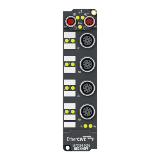
 ...................... 11 EPP31xx - Technical data ....................... 12 Additional checks.......................... 12 EPP3174-0002, EPP3184-0002 – Process image ................ 13 3 Mounting and cabling.......................... 14 Mounting ............................ 14 3.1.1 Dimensions ........................ 14 3.1.2 Fixing ..........................
  • Page 4 4.11 EPP31x4-0002 - Object overview.................... 70 4.12 EPP31x4 - Object description and parameterization ............... 76 4.13 Restoring the delivery state ...................... 91 5 Appendix .............................. 92 General operating conditions...................... 92 EtherCAT Box- / EtherCAT P Box - Accessories ................ 93 Support and Service ........................ 94 Version: 1.0.0 EPP3174, EPP3184...
  • Page 5: Foreword

    The TwinCAT Technology is covered, including but not limited to the following patent applications and patents: EP0851348, US6167425 with corresponding applications or registrations in various other countries. ® EtherCAT is registered trademark and patented technology, licensed by Beckhoff Automation GmbH, Germany. Copyright © Beckhoff Automation GmbH & Co. KG, Germany.
  • Page 6: Safety Instructions

    All the components are supplied in particular hardware and software configurations appropriate for the application. Modifications to hardware or software configurations other than those described in the documentation are not permitted, and nullify the liability of Beckhoff Automation GmbH & Co. KG. Personnel qualification This description is only intended for trained specialists in control, automation and drive engineering who are familiar with the applicable national standards.
  • Page 7: Documentation Issue Status

    WW - week of production (calendar week) 29 - week of production 29 YY - year of production 10 - year of production 2010 FF - firmware version 02 - firmware version 02 HH - hardware version 01 - hardware version 01 EPP3174, EPP3184 Version: 1.0.0...
  • Page 8: Product Overview

    • digital outputs with 0.5 or 2 A output current • analog inputs and outputs with 16 bit resolution • Thermocouple and RTD inputs • Stepper motor modules XFC (eXtreme Fast Control Technology) modules, including inputs with time stamp, are also available. Version: 1.0.0 EPP3174, EPP3184...
  • Page 9: Fig. 2 Ethercat P Box With M8 Connections For Sensors/Actuators

    EtherCAT, which is available for download from our website (www.beckhoff.com) under Downloads. XML files You will find XML files (XML Device Description Files) for Beckhoff EtherCAT P modules on our website (www.beckhoff.com) under Downloads, in the Configuration Files area. EPP3174, EPP3184...
  • Page 10: Epp3174-0002 - Introduction

    EPP3174-0002 - Introduction Fig. 4: EPP3174-0002 The EPP3174 EtherCAT P Box has four analog inputs which can be individually parameterized, so that they process signals either in the -10 to +10 V range or the 0 mA/4 mA…20 mA range. The voltage or input current is digitized with a resolution of 16 bits, and is transmitted (electrically isolated) to the higher-level automation device.
  • Page 11: Epp3184-0002 - Introduction

    The inputs can, if required, be scaled differently, and automatic limit value monitoring is also available. EtherCAT is used for parameterization purposes. The parameters are stored in the module. EPP3174, EPP3184 Version: 1.0.0...
  • Page 12: Epp31Xx - Technical Data

    Vibration 10 frequency runs in 3 axes 5 Hz < f < 60 Hz displacement 0.35 mm, constant amplitude 60.1 Hz < f < 500 Hz acceleration 5 g, constant amplitude Shocks 1000 shocks in each direction, in 3 axes 35 g, 11 ms Version: 1.0.0 EPP3174, EPP3184...
  • Page 13: Epp3174-0002, Epp3184-0002 - Process Image

    Product overview EPP3174-0002, EPP3184-0002 – Process image The process data of the EPP3174-0002 and EPP3184-0002 modules are identical in the default setting and are illustrated here taking the EPP3174-0002 as an example. A detailed explanation of the meaning of the status bits can be found in the chapters EPP31xx - Settings [} 62] and Object description and parameterization [} 87].
  • Page 14: Mounting And Cabling

    Mounting and cabling Mounting and cabling Mounting 3.1.1 Dimensions Fig. 6: Dimensions of the EtherCAT-P-Box Modules All dimensions are given in millimeters. Version: 1.0.0 EPP3174, EPP3184...
  • Page 15: Fig. 7 Fe Socket In Housing Of Ethercat-P-Box

    Metal parts Brass, nickel-plated Contacts CuZn, gold-plated Installation position variable Protection class IP65, IP66, IP67 (conforms to EN 60529) when screwed together Dimensions (H x W x D) ca. 126 x 30 x 26,5 mm Weight approx. 125 g, depending on module type EPP3174, EPP3184 Version: 1.0.0...
  • Page 16: Fixing

    The mounting rail ZS5300-0011 (500 mm x 129 mm) has in addition to the M3 treads also pre-made M4 treads to fix 60 mm wide modules via their middle holes. Up to 14 narrow or 7 wide modules may be mixed mounted. Version: 1.0.0 EPP3174, EPP3184...
  • Page 17: Nut Torque For Connectors

    ZB8800 is also a max. torque of 0.5 Nm permissible. Fig. 9: EtherCAT P Box with M8 connectors M12 connectors It is recommended to pull the M12 connectors tight with a nut torque of 0.6 Nm. Fig. 10: EtherCAT P Box with M8 and M12 connectors EPP3174, EPP3184 Version: 1.0.0...
  • Page 18: Fig. 11 7/8" Connectors

    It is recommended to pull the 7/8" connectors tight with a nut torque of 1.5 Nm. Fig. 11: 7/8" connectors Torque socket wrenches Fig. 12: ZB8801 torque socket wrench Ensure the right torque Use the torque socket wrenches available by Beckhoff to pull the connectors tight (see ZB8800, ZB8801-0000)! Version: 1.0.0 EPP3174, EPP3184...
  • Page 19: Ethercat P

    Fig. 13: EtherCAT P Box: M8 (30 mm housing) Assignment A standard industrial CAT5 cable is used to which an EtherCAT-P-coded M8 plug is connected. The assignment of the Beckhoff EtherCAT-P-cable is listed below. Assignment EtherCAT P Connector Wire color cable...
  • Page 20: Ethercat P - Calculate The Cable Length, Voltage And Current

    Status of the EtherCAT P module is operational EtherCAT statuses The various statuses in which an EtherCAT P module may be found are described in the Basic Sys- tem Documentation for EtherCAT, which is available for download from our website (www.beck- hoff.com) under Downloads. Version: 1.0.0 EPP3174, EPP3184...
  • Page 21: Ethercat-P-Supply

    Rx - Auxiliary voltage U , +24 V Tx - Control voltage U , +24 V Housing Shield Shielding The pins M8 connectors carry a maximum current of 3 A. Two LEDs display the status of the supply voltages. EPP3174, EPP3184 Version: 1.0.0...
  • Page 22 - this means, for instance, that in the case of 0...10 V inputs, any reference voltage (0...30 V) may be connected to U ; this is then available to the sensors (e.g. smoothed 10 V for measuring potentiometers). Version: 1.0.0 EPP3174, EPP3184...
  • Page 23: Status Leds For Power Supply

    Because of overload (current > 0.5 A) the sensor supply generated from power supply voltage U was switched off for all sensors fed from this. (Auxiliary voltage) The power supply voltage U is not present green illuminated The power supply voltage U is present EPP3174, EPP3184 Version: 1.0.0...
  • Page 24: Ethercat P Cable Conductor Losses M8

    Conductor losses on the EtherCAT P cables Fig. 18: Conductor losses on the EtherCAT P cables Example A 10 meter-long EtherCAT P cable with a cross section of 0.34 mm² has a voltage drop of ∼3.0 V with a load of 3 A. Version: 1.0.0 EPP3174, EPP3184...
  • Page 25: Cabling

    Cabling A list of the EtherCAT P cable, EtherCAT cable, power cable, sensor cable, Ethernet-/EtherCAT connectors and the field assembled connectors can be found at the following link: https://beckhoff.de/english/ethercat- box/ethercat_box_cables.htm?id=690338951657421 You can find the corresponding data sheets at the following link: https://beckhoff.de/english/ downloadfinder/default.htm?id=109075571109075577&cat1=40717316&cat2=90800914...
  • Page 26: Fig. 20 Ethercat-P-Box-Accessories

    M12 Sensor cable Shielded cables for M12 I/O connection sockets M12 Sensor cable, shielded EtherCAT P connectors for field assembly For EtherCAT P are field installable M8 connectors as plug and as socket available. Fig. 21: EtherCAT P: field assembly connectors Version: 1.0.0 EPP3174, EPP3184...
  • Page 27: Fig. 22 Selection Of Different Sensor Cables From Beckhoff

    Mounting and cabling Sensor cable Fig. 22: Selection of different Sensor cables from Beckhoff EPP3174, EPP3184 Version: 1.0.0...
  • Page 28: Signal Connection

    The input voltage is measured as a differential signal. Fig. 23: M12 analog voltage inputs, one differential input per socket GND connections If several sensors are connected to a box whose GND connections are not electrically isolated, GND must be connected to GNDp. Version: 1.0.0 EPP3174, EPP3184...
  • Page 29: Fig. 24 M12 Analog Current Inputs, One Differential Input Per Socket

    The input current is measured as a differential signal. Fig. 24: M12 analog current inputs, one differential input per socket GND connections If several sensors are connected to a box whose GND connections are not electrically isolated, GND must be connected to GNDp. EPP3174, EPP3184 Version: 1.0.0...
  • Page 30: Epp3184-0002

    Analog input, 0 to 20 mA, or 4 to 20 mA Fig. 26: M12 analog current inputs, one single-ended input per socket GND connections If several sensors are connected to a box whose GND connections are not electrically isolated, GND must be connected to GNDp. Version: 1.0.0 EPP3174, EPP3184...
  • Page 31: Status Leds At The M12 Connections

    Data transfer to A/D converter left Function OK Error: Broken wire or measured value outside the measuring right range Correct function is indicated if the green RUN LED is on and the red Error LED is off. EPP3174, EPP3184 Version: 1.0.0...
  • Page 32: Configuration

    This test can be parameterized in the extended device settings. To take advantage of the current features/settings of the master, the latest version of the ESI file should always be downloaded. Therefore it is necessary to consider the following note first. Version: 1.0.0 EPP3174, EPP3184...
  • Page 33 (default: C:\TwinCAT\IO\EtherCAT). The files are read (once) when a new System Manager window is opened. A TwinCAT installation includes the set of Beckhoff ESI files that was current at the time when the TwinCAT build was created. For TwinCAT 2.11 and higher, the ESI di- rectory can be uploaded from the System Manager, if the programming PC is connected to the in- ternet (TwinCAT →...
  • Page 34: Fig. 28 Appending A New I/O Device (I/O Devices -> Right-Click -> Append Device

    Configuration Fig. 28: Appending a new I/O device (I/O Devices -> right-click -> Append Device...) Fig. 29: Selecting the device EtherCAT • Append a new box. Version: 1.0.0 EPP3174, EPP3184...
  • Page 35: Fig. 30 Appending A New Box (Device -> Right-Click -> Append Box

    Configuration Fig. 30: Appending a new box (Device -> right-click -> Append Box...) • In the dialog that appears select the desired box (e.g. EPP1322-0001), and confirm with OK. Fig. 31: Selecting a Box (e.g. EPP1322-0001) EPP3174, EPP3184 Version: 1.0.0...
  • Page 36: Online Configuration Settings - Twincat

    (default: C:\TwinCAT\IO\EtherCAT). The files are read (once) when a new Sys- tem Manager window is opened. A TwinCAT installation includes the set of Beckhoff ESI files that was current at the time when the TwinCAT build was created. For TwinCAT 2.11 and higher, the ESI directory can be uploaded from the System Manager, if the programming PC is connected to the internet (TwinCAT →...
  • Page 37: Fig. 32 Twincat Config Mode Display

    TwinCAT icon next to the Windows clock always shows the TwinCAT mode of the local IPC. The System Manager window shows the TwinCAT state of the target system. Right-clicking on “I/O Devices” in the configuration tree opens the search dialog. EPP3174, EPP3184 Version: 1.0.0...
  • Page 38: Fig. 33 Scan Devices

    If the scan agent detects from the response that an EtherCAT/EtherCAT P slave is connected, the port is immediately shown as an “EtherCAT Device”. Fig. 35: detected Ethernet devices After confirmation with “OK” a device scan is suggested for all selected devices, see following figure. Version: 1.0.0 EPP3174, EPP3184...
  • Page 39: Fig. 36 Scan Query After Automatic Creation Of An Ethercat Device

    • “frames/sec” should match the cycle time taking into account the sent number of frames • no excessive “LostFrames” or CRC errors should occur The configuration is now complete. It can be modified as described under the offline procedure. EPP3174, EPP3184 Version: 1.0.0...
  • Page 40: Fig. 38 Master Display After Scan For Boxes

    This enables the configuration to be compared. Fig. 39: identical configuration If differences are detected, they are shown in the correction dialog, so that the user can modify the configuration as required. Version: 1.0.0 EPP3174, EPP3184...
  • Page 41: Fig. 40 Correction Dialog

    This is backward compatible, i.e. newer devices (higher revision) should be supported if the EtherCAT/EtherCAT P master addresses them as an older revision. The following compatibility rule of thumb is to be assumed for Beckhoff EtherCAT Terminals and EtherCAT/EtherCAT P Boxes: Device revision in the system >= device revision in the configuration...
  • Page 42: Fig. 41 Correction Dialog With Modifications

    Configuration Fig. 41: correction dialog with modifications Once all modifications have been saved or accepted, click “OK” to transfer them to the real *.tsm configuration. Version: 1.0.0 EPP3174, EPP3184...
  • Page 43: Configuration Via Twincat

    Configuration via TwinCAT In the left-hand window of the TwinCAT System Manager, click on the branch of the EtherCAT P Box you wish to configure (EPP3174-0002 in this example). Fig. 42: Branch of the EtherCAT P box to be configured In the right-hand window of the TwinCAT System manager, various tabs are now available for configuring the EtherCAT P Box.
  • Page 44: Fig. 44 Ethercat Tab

    EtherCAT P device to which this device is to be connected can be selected. Advanced Settings This button opens the dialogs for advanced settings. The link at the bottom of the tab points to the product page for this EtherCAT P device on the web. Version: 1.0.0 EPP3174, EPP3184...
  • Page 45 B). Fig. 46: Tab EtherCAT P: One device connected to junction device Are three devices connected to the three ports of the junction device (A), the ports are displayed (B) as shown in the figure below. EPP3174, EPP3184 Version: 1.0.0...
  • Page 46 Configuration Fig. 47: Tab EtherCAT P: Three devices connected to junction device How you can see the topology of your EtherCAT P system in TwinCAT, is described here [} 48]. Version: 1.0.0 EPP3174, EPP3184...
  • Page 47 Resistor: electronic, passive components e.g. relay, coil If you click on the button “Check EtherCAT P System”, all devices that are attached to your TwinCAT tree are listed as shown in the following figure. Fig. 48: Check EtherCAT P System EPP3174, EPP3184 Version: 1.0.0...
  • Page 48 New voltage feed. Topology of the EtherCAT P system You can view the topology of your EtherCAT P system, as described in the figure below: A: Click in the TwinCAT tree on „Device1 (EtherCAT)“ B: Click on tab „EtherCAT“ Version: 1.0.0 EPP3174, EPP3184...
  • Page 49 Indicates the configuration of the process data. The input and output data of the EtherCAT P slave are represented as CANopen process data objects (PDO). The user can select a PDO via PDO assignment and modify the content of the individual PDO via this dialog, if the EtherCAT P slave supports this function. EPP3174, EPP3184 Version: 1.0.0...
  • Page 50 Activation of PDO assignment • the EtherCAT P slave has to run through the PS status transition cycle (from pre-operational to safe-operational) once (see Online tab [} 55]), • and the System Manager has to reload the EtherCAT P slaves ( button) Version: 1.0.0 EPP3174, EPP3184...
  • Page 51 It is also possible to add new mailbox requests to the list display. The download requests are sent to the slave in the same order as they are shown in the list. EPP3174, EPP3184 Version: 1.0.0...
  • Page 52 (CoE) protocol. This dialog lists the content of the object list of the slave (SDO upload) and enables the user to modify the content of an object from this list. Details for the objects of the individual EtherCAT P devices can be found in the device-specific object descriptions. Version: 1.0.0 EPP3174, EPP3184...
  • Page 53 Configuration Fig. 54: CoE - Online tab EPP3174, EPP3184 Version: 1.0.0...
  • Page 54 Offline If this option button is selected, the list of the objects included in the object list is - via EDS File read from an EDS file provided by the user. Version: 1.0.0 EPP3174, EPP3184...
  • Page 55 A carrier signal is available at the port, but the port is closed. File Access over EtherCAT Download With this button a file can be written to the EtherCAT P device. Upload With this button a file can be read from the EtherCAT P device. EPP3174, EPP3184 Version: 1.0.0...
  • Page 56: Notices On Analog Specifications

    Analogous to pointing devices this is the measuring scale (see IEC 61131) or also the dynamic range. For analog I/O devices from Beckhoff the rule is that the limit with the largest value is chosen as the full scale value of the respective product (also called the reference value) and is given a positive sign. This applies to both symmetrical and asymmetrical measuring spans.
  • Page 57 In particular this also applies to SE, even though the term suggest that only one wire is required. • The term "electrical isolation" should be clarified in advance. Beckhoff IO modules feature 1…8 or more analog channels; with regard to the channel connection a distinction is made in terms of: ◦...
  • Page 58 The property of electrical isolation indicates whether the channels are directly connected to each other. • Beckhoff terminals/boxes always feature electrical isolation between the field/analog side and the bus/ EtherCAT side. In other words, if two analog terminals/boxes are not connected via the power contacts, the modules are effectively electrically isolated.
  • Page 59 One or two further sensor cables are used for the signal transmission of the current loop: 1. sensor cable: according to the Beckhoff terminology such sensors are to be connected to ‘single- ended’ inputs in 3 cables with +/-/Signal lines and if necessary FE/shield 2.
  • Page 60 Configuration Fig. 59: 2/3/4-wire connection as single-ended or differential connection technology Version: 1.0.0 EPP3174, EPP3184...
  • Page 61: Epp31Xx - Settings

    Set the correct signal type before connecting the sensors! This setting can be made individually for each channel in the CoE object 0xF800:0n [} 80]. Changes are immediately effective. Fig. 60: EPP3174-0002, EPP3184-0002: Selection of the signal type 4.5.2 Representation Presentation, index 0x80n0:02 [} 77] The measured value output is set in factory to two's complement representation (signed integer).
  • Page 62: Siemens Bits

    0x60n0:03 [} 87] and 0x60n0:05 [} 87] are set accordingly (see sample below). The indices 0x80n0:07 [} 77] or 0x80n0:08 [} 77] serve to activate the limit value monitoring. Output limit n (2-bit): • 0: not active • 1: Value < limit value Version: 1.0.0 EPP3174, EPP3184...
  • Page 63 VariableSizeMismatch dialog as described in the chapter Process data. • Additional task 2-bit variables can be created in the System Manager. Linking of 2-bit variable to additional task EPP3174, EPP3184 Version: 1.0.0...
  • Page 64 • 2: value > limit value • 3: Value is equal to the limit value TRUE • 0: not active • 1: value > limit value • 2: value < limit value • 3: Value is equal to the limit value Version: 1.0.0 EPP3174, EPP3184...
  • Page 65: Epp31Xx - Operating Modes

    The "input-based" mode shifts the sync-interrupt in such a way that the process data are ready for collection shortly before the current process data cycle. EPP3174, EPP3184 Version: 1.0.0...
  • Page 66 Fig. 61: typical attenuation curve of notch filter at 50 Hz Filter data FIR filter (1- to 4-channel modules) Filter Attenuation Limit frequency (-3 dB) Conversion time 50 Hz FIR > 50 dB 22 Hz 625 µs 60 Hz FIR > 45 dB 26 Hz 521 µs Version: 1.0.0 EPP3174, EPP3184...
  • Page 67: Data Stream

    24 Hz IIR 6 12 Hz IIR 7 6.2 Hz IIR 8 3.0 Hz Data stream The following flow chart illustrates the data stream of the EPP31xx (processing of raw data). Fig. 62: Diagram showing the data stream in the EPP31xx EPP3174, EPP3184 Version: 1.0.0...
  • Page 68: Measuring Ranges

    EPP3174-0002, EPP3184-0002 (0…20 mA) Fig. 63: Data flow with correction calculation for 0…20 mA EPP3174-0002, EPP3184-0002 (4…20 mA) Fig. 64: Data flow with correction calculation for 4…20 mA EPP3174-0002, EPP3184-0002 (+/- 10 V) Fig. 65: Data flow with correction calculation for +/- 10 V Version: 1.0.0 EPP3174, EPP3184...
  • Page 69: Calibration

    Fig. 66: Data flow with correction calculation for 0…10 V Calibration The concept "calibration", which has historical roots at Beckhoff, is used here even if it has nothing to do with the deviation statements of a calibration certificate. • Vendor calibration, index 0x80n0:0B The vendor calibration is enabled via index 0x80n0:0B.
  • Page 70: Calculation Of Process Data

    EtherCAT XML Device Description The display matches that of the CoE objects from the EtherCAT XML Device Description. We rec- ommend downloading the latest XML file from the download area of the Beckhoff website and in- stalling it according to installation instructions.
  • Page 71 0x6020:11, 16 Subindex AI TxPDO-Map Standard Ch.4 0x0B (11 1A06:0 [} 84] 1A06:01 SubIndex 001 0x6030:01, 1 1A06:02 SubIndex 002 0x6030:02, 1 1A06:03 SubIndex 003 0x6030:03, 2 1A06:04 SubIndex 004 0x6030:05, 2 1A06:05 SubIndex 005 0x6030:07, 1 EPP3174, EPP3184 Version: 1.0.0...
  • Page 72 0x00 (0 6010:0F TxPDO State 0x00 (0 6010:10 TxPDO Toggle 0x00 (0 6010:11 Value 0x0000 (0 Subindex AI Inputs 0x11 (17 6020:0 [} 88] 6020:01 Underrange 0x00 (0 6020:02 Overrange 0x00 (0 6020:03 Limit 1 6020:05 Limit 2 Version: 1.0.0 EPP3174, EPP3184...
  • Page 73 User scale offset 0x0000 (0 8010:12 User scale gain 0x00010000 (65536 8010:13 Limit 1 0x0000 (0 8010:14 Limit 2 0x0000 (0 8010:15 Filter settings 0x0000 (0 8010:17 User calibration offset 0x0000 (0 8010:18 User calibration gain 0x4000 (16384 EPP3174, EPP3184 Version: 1.0.0...
  • Page 74 AI Internal data 0x01 (1 803E:0 [} 89] 803E:01 ADC raw value 0x0000 (0 Subindex AI Vendor data 0x06 (6 803F:0 [} 89] 803F:01 R0 Offset 0x0000 (0 803F:02 R0 Gain 0x4000 (16384 803F:03 R1 Offset 0x0000 (0 Version: 1.0.0 EPP3174, EPP3184...
  • Page 75 Input type Ch3 0x0000 (0 F800:04 Input type Ch4 0x0000 (0 F800:05 Enable Filter Settings Per Channel Flags: RO (Read Only): this object can be read only RW (Read/Write): this object can be read and written to EPP3174, EPP3184 Version: 1.0.0...
  • Page 76: Epp31X4 - Object Description And Parameterization

    EtherCAT XML Device Description The display matches that of the CoE objects from the EtherCAT XML Device Description. We rec- ommend downloading the latest XML file from the download area of the Beckhoff website and in- stalling it according to installation instructions.
  • Page 77 IIR 1 IIR 2 IIR 3 IIR 4 IIR 5 IIR 6 IIR 7 IIR 8 8000:17 User calibration offset User calibration: Offset INT16 0x0000 (0 8000:18 User calibration gain User calibration: Gain INT16 0x0000 (0 EPP3174, EPP3184 Version: 1.0.0...
  • Page 78 IIR 1 IIR 2 IIR 3 IIR 4 IIR 5 IIR 6 IIR 7 IIR 8 8010:17 User calibration offset User calibration: Offset INT16 0x0000 (0 8010:18 User calibration gain User calibration: Gain INT16 0x0000 (0 Version: 1.0.0 EPP3174, EPP3184...
  • Page 79 IIR 1 IIR 2 IIR 3 IIR 4 IIR 5 IIR 6 IIR 7 IIR 8 8020:17 User calibration offset User calibration: Offset INT16 0x0000 (0 8020:18 User calibration gain User calibration: Gain INT16 0x0000 (0 EPP3174, EPP3184 Version: 1.0.0...
  • Page 80 Input signal range for channel 3 (values see chan- UINT16 0x0000 (0 nel 1) F800:04 Input type Ch4 Input signal range for channel 4 (values see chan- UINT16 0x0000 (0 nel 1) F800:05 Enable Filter Set- BOOLEAN tings Per Channel Version: 1.0.0 EPP3174, EPP3184...
  • Page 81 AI TxPDO-Par Stan- PDO parameter TxPDO 1 UINT8 0x06 (6 dard Ch.1 1800:06 Exclude TxPDOs Specifies the TxPDOs (index of TxPDO mapping ob- OCTET- 01 1A jects) that must not be transferred together with TxPDO STRING[2] EPP3174, EPP3184 Version: 1.0.0...
  • Page 82 1807:0 AI TxPDO-Par PDO parameter TxPDO 8 UINT8 0x06 (6 Compact Ch.4 1807:06 Exclude TxPDOs Specifies the TxPDOs (index of TxPDO mapping ob- OCTET- 06 1A jects) that must not be transferred together with TxPDO STRING[2] Version: 1.0.0 EPP3174, EPP3184...
  • Page 83 Index (hex) Name Meaning Data type Flags Default 1A03:0 AI TxPDO-Map PDO Mapping TxPDO 4 UINT8 0x01 (1 Compact Ch.2 1A03:01 SubIndex 001 1. PDO Mapping entry (object 0x6010 (AI Inputs), entry UINT32 0x6010:11, 16 0x11 (Value)) EPP3174, EPP3184 Version: 1.0.0...
  • Page 84 Index (hex) Name Meaning Data type Flags Default 1A07:0 AI TxPDO-Map PDO Mapping TxPDO 8 UINT8 0x01 (1 Compact Ch.4 1A07:01 SubIndex 001 1. PDO Mapping entry (object 0x6030 (AI Inputs), entry UINT32 0x6030:11, 16 0x11 (Value)) Version: 1.0.0 EPP3174, EPP3184...
  • Page 85 Subindex 003 3. allocated TxPDO (contains the index of the associ- UINT16 0x1A04 (6660 ated TxPDO mapping object) 1C13:04 Subindex 004 4. allocated TxPDO (contains the index of the associ- UINT16 0x1A06 (6662 ated TxPDO mapping object) EPP3174, EPP3184 Version: 1.0.0...
  • Page 86 0x0000 (0 counter 1C33:0D Shift too short UINT16 0x0000 (0 counter 1C33:20 Sync error BOOLEAN 0x00 (0 Profile-specific objects (0x6000-0xFFFF) The profile-specific objects have the same meaning for all EtherCAT slaves that support the profile 5001. Version: 1.0.0 EPP3174, EPP3184...
  • Page 87 Validity of the data of the associated TxPDO BOOLEAN 0x00 (0 valid invalid 6010:10 TxPDO Toggle TxPDO toggle is toggled by the slave when the data of BOOLEAN 0x00 (0 the associated TxPDO is updated. 6010:11 Value Analog input date INT16 0x0000 (0 EPP3174, EPP3184 Version: 1.0.0...
  • Page 88 0x0000 (0 Index 800E AI Internal data Index (hex) Name Meaning Data type Flags Default 800E:0 AI internal data Maximum subindex UINT8 0x01 (1 800E:01 ADC raw value Raw value of the analog/digital converter INT16 0x0000 (0 Version: 1.0.0 EPP3174, EPP3184...
  • Page 89 803F:03 R1 Offset Offset (vendor calibration) INT16 0x0000 (0 803F:04 R1 Gain Gain (vendor calibration) INT16 0x4000 (16384 803F:05 R2 Offset Offset (vendor calibration) INT16 0x0000 (0 803F:06 R2 Gain Gain (vendor calibration) INT16 0x4000 (16384 EPP3174, EPP3184 Version: 1.0.0...
  • Page 90 Data type Flags Default F010:0 Module list Maximum subindex UINT8 0x05 (5 F010:01 SubIndex 001 UINT32 0x0000012C (300 F010:02 SubIndex 002 UINT32 0x0000012C (300 F010:03 SubIndex 003 UINT32 0x0000012C (300 F010:04 SubIndex 004 UINT32 0x0000012C (300 Version: 1.0.0 EPP3174, EPP3184...
  • Page 91: Restoring The Delivery State

    Alternative restore value In some older terminals / boxes the backup objects can be switched with an alternative restore value: Decimal value: 1819238756 Hexadecimal value: 0x6C6F6164 An incorrect entry for the restore value has no effect. EPP3174, EPP3184 Version: 1.0.0...
  • Page 92: Appendix

    (ph-Value > 12) > 40°C: not resistant Acetic acid not resistant Argon (technical clean) resistant • resistant: Lifetime several months • non inherently resistant: Lifetime several weeks • not resistant: Lifetime several hours resp. early decomposition Version: 1.0.0 EPP3174, EPP3184...
  • Page 93: Ethercat Box- / Ethercat P Box - Accessories

    M12/wrench size 13, for torque wrench ZB8801-0000 ZB8801-0003 torque cable key, M12 field assembly/wrench size 13, for torque wrench ZB8801-0000 Further accessories Further accessories may be found at the price list for Beckhoff fieldbus components and at the inter- net under https://www.beckhoff.com EPP3174, EPP3184 Version: 1.0.0...
  • Page 94: Support And Service

    Beckhoff's branch offices and representatives Please contact your Beckhoff branch office or representative for local support and service on Beckhoff products! The addresses of Beckhoff's branch offices and representatives round the world can be found on her internet pages: http://www.beckhoff.com You will also find further documentation for Beckhoff components there.
  • Page 95 EtherCAT-P-Box-accessories...................... Fig. 21 EtherCAT P: field assembly connectors ..................Fig. 22 Selection of different Sensor cables from Beckhoff ..............Fig. 23 M12 analog voltage inputs, one differential input per socket............Fig. 24 M12 analog current inputs, one differential input per socket ............
  • Page 96 Single-ended/differential typification .................... Fig. 59 2/3/4-wire connection as single-ended or differential connection technology......Fig. 60 EPP3174-0002, EPP3184-0002: Selection of the signal type ............. Fig. 61 typical attenuation curve of notch filter at 50 Hz ................Fig. 62 Diagram showing the data stream in the EPP31xx ..............

This manual is also suitable for:

Epp3184

Table of Contents