
Related Manuals for Beckhoff EPI2 Series


Summary of Contents for Beckhoff EPI2 Series
- Page 1 Documentation EPI2xxx IO-Link-Box Modules with digital inputs Version: 1.1.0 Date: 2015-09-22...
-
Page 3: Table Of Contents
Table of contents Table of contents 1 Foreword .............................. 5 Notes on the documentation...................... 5 Safety instructions .......................... 6 Documentation issue status...................... 7 2 Product overview............................ 8 EPI2xxx Module overview......................... 8 EPI2008 ............................ 9 2.2.1 EPI2008 - Introduction ...................... 9 2.2.2 EPI2008 - Technical Data .................... 10 2.2.3 EPI2008-000x - Process image .................. 11 EPI2809 ............................ - Page 4 Table of contents 5.4.1 Digital outputs M8 and M12 .................... 86 5.4.2 Digital in-/outputs M8 and M12 ................... 86 UL Requirements.......................... 87 6 Cabling .............................. 88 7 Appendix .............................. 89 General operating conditions...................... 89 IP67 Box - Accessories........................ 90 Support and Service ........................ 91 Version: 1.1.0 EPI2xxx...
-
Page 5: Foreword
EP0851348, US6167425 with corresponding applications or registrations in various other countries. ® EtherCAT is registered trademark and patented technology, licensed by Beckhoff Automation GmbH, Germany Copyright © Beckhoff Automation GmbH & Co. KG, Germany. The reproduction, distribution and utilization of this document as well as the communication of its contents to others without express authorization are prohibited. -
Page 6: Safety Instructions
All the components are supplied in particular hardware and software configurations appropriate for the application. Modifications to hardware or software configurations other than those described in the documentation are not permitted, and nullify the liability of Beckhoff Automation GmbH & Co. KG. Personnel qualification This description is only intended for trained specialists in control, automation and drive engineering who are familiar with the applicable national standards. -
Page 7: Documentation Issue Status
Foreword Documentation issue status Version Changes 1.1.0 • EPI2008-000x – Object description and parameterization updated • EPI2809-002x – Object description and parameterization updated • EPI2338-000x – Object description and parameterization updated • EPI2339-002x – Object description and parameterization updated 1.0.0 •... -
Page 8: Product Overview
Product overview Product overview EPI2xxx Module overview Digital output modules Module Signal connec- Number of out- Current Comment tion puts 8 x M8 0.5 A (Σ 4 A) Maximum of the total of all EPI2008-0001 outputs 4 A [} 9] 4 x M12 0.5 A (Σ 4 A) Maximum of the total of all EPI2008-0002 outputs 4 A... -
Page 9: Epi2008
Product overview EPI2008 2.2.1 EPI2008 - Introduction Fig. 1: EPI2008-0001 Fig. 2: EPI2008-0002 8 digital outputs, 24 V DC, Imax 0.5 A The EPI2008 IO-Link Box with digital outputs connects binary control signals from the controller to the actuators at the process level. The 8 outputs handle load currents of up to 0.5 A, and indicate their status through light emitting diodes. -
Page 10: Epi2008 - Technical Data
Product overview Quick links Installation 2.2.2 EPI2008 - Technical Data Technical data EPI2008-0001 EPI2008-0002 Communication IO-Link Data transfer rate 230,4 kBaud (COM 3) IO-Link connection 1 x M12 connector, a-coded Specification version IO-Link V1.1, Class B Requirements IO-Link Master V1.1 Number of outputs Output connections Load type Ohmic, inductive, lamp load... -
Page 11: Epi2008-000X - Process Image
Product overview 2.2.3 EPI2008-000x - Process image Output 0 to Output 7 The IO-Link device is connected to IO-Link Port1 of the IO-Link master (EP6224-3022). You will find the 8 digital outputs to the module (here using the EPI2008-0001 as an example) under Output 0 to Output 7. -
Page 12: Epi2809
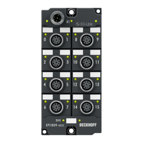
Product overview EPI2809 2.3.1 EPI2809 - Introduction Fig. 4: EPI2809-0021 Fig. 5: EPI2809-0022 16 digital outputs 24 V 0.5 A (Σ 4 A) The EPI2809 IO-Link Box with digital outputs connects the binary control signals from the controller on to the actuators at the process level. The 16 outputs handle load currents of up to 0.5 A each, although the total current is limited to 4 A. -
Page 13: Epi2809 - Technical Data
Product overview The signal state is indicated by means of light emitting diodes. The signals are connected via M8 connectors (EPI2809-0021) or M12 connectors (EPI2809-0022). All outputs are short-circuit-proof and protected against inverse connection. Quick links Installation 2.3.2 EPI2809 - Technical data Technical data EPI2809-0021 EPI2809-0022... -
Page 14: Epi2809-002X - Process Image
Product overview 2.3.3 EPI2809-002x - Process image Output 0 to Output 15 The IO-Link device is connected to IO-Link Port1 of the IO-Link master (EP6224-3022). You will find the 16 digital outputs to the module (here using the EPI2809-0021 as an example) under Output 0 to Output 15. -
Page 15: Epi2338
Product overview EPI2338 2.4.1 EPI2338 - Introduction Fig. 7: EPI2338-0001 Fig. 8: EPI2338-0002 8 digital in or outputs, 24 V The EPI2338 IO-Link Box has eight digital channels, each of which can optionally be operated as an input or as an output. A configuration if a channel should be used as input or as an output is not necessary; the input circuit is internally connected to the output driver, so a set output is displayed automatically to the input process image. - Page 16 Product overview The state of each signal is indicated by means of light emitting diodes. The signals are connected, optionally, via M8 connectors (EPI2338-x001) or M12 connectors (EPI2338-x002). The connected sensors are powered via 2L , not from L The IO-Link Box EPI2338 supplies digital sensors in contrast to many other modules from the additional supply voltage 2L , not from the voltage L ! This happens because the con-...
-
Page 17: Epi2338 - Technical Data
Product overview 2.4.2 EPI2338 - Technical Data Technical data EPI2338-0001 EPI2338-0002 Communication IO-Link Data transfer rate 230,4 kBaud (COM 3) IO-Link connection 1 x M12 connector, a-coded Specification version IO-Link V1.1, Class B Requirements IO-Link Master V1.1 Number of outputs 8 to 0 Output connections [} 86] Load type ohmic, inductive, lamp load... -
Page 18: Epi2338-000X - Process Image
Product overview 2.4.3 EPI2338-000x - Process image Inputs and Outputs The IO-Link device is connected to IO-Link Port1 of the IO-Link master (EP6224-3022). You will find the 8 digital inputs to the module (here using the EPI2338-0001 as an example) under Input 0 to Input 7 and the 8 digital outputs under Output 0 to Output 7. -
Page 19: Epi2339
Product overview EPI2339 2.5.1 EPI2339 - Introduction Fig. 10: EPI2339-0021 Fig. 11: EPI2339-0022 16 digital in or outputs, 24 V The EPI2339 IO-Link Box has 16 digital channels, each of which can optionally be operated as an input or as an output. A configuration if a channel should be used as input or as an output is not necessary; the input circuit is internally connected to the output driver, so a set output is displayed automatically to the input process image. - Page 20 Product overview The state of each signal is indicated by means of light emitting diodes. The signals are connected via M8 connectors (EPI2339-0021) or M12 connectors (EPI2339-0022). The connected sensors are powered via 2L , not from L The IO-Link Box EPI2339 supplies digital sensors in contrast to many other modules from the additional supply voltage 2L , not from the voltage L ! This happens because the con-...
-
Page 21: Epi2339 - Technical Data
Product overview 2.5.2 EPI2339 - Technical data Technical data EPI2339-0021 EPI2339-0022 Communication IO-Link Data transfer rate 230,4 kBaud (COM 3) IO-Link connection 1 x M12 connector, a-coded Specification version IO-Link V1.1, Class B Requirements IO-Link Master V1.1 Number of outputs 16 to 0 Output connections [} 86] Load type ohmic, inductive, lamp load... -
Page 22: Epi2339-002X - Process Image
Product overview 2.5.3 EPI2339-002x - Process image Inputs and Outputs The IO-Link device is connected to IO-Link Port1 of the IO-Link master (EP6224-3022). You will find the 16 digital inputs to the module under Input 0 to Input 15 and the 16 digital outputs under Output 0 to Output 15 (here using the EPI2339-0021 as an example). -
Page 23: Io-Link Basics
IO-Link master provides the interface to the higher-level controller and controls communication with the connected IO-Link devices. The Beckhoff EP6224-xxxx IO-Link Master module has four IO-Link ports. One IO-Link device can be connected to each of them. IO-Link is not a fieldbus, but rather a peer-to-peer connection (see following figure). -
Page 24: Fig. 13 Io-Link Overview: Peer-To-Peer Communication
IO-Link basics Fig. 13: IO-Link overview: Peer-to-Peer communication The connected IO-Link devices possess individual parameter information, which is recognized during automatic scanning with TwinCAT and adopted into the System Manager (see also the chapter "Basic function principles“, Integrating IO-Link devices). Offline can be read module specific information in form of an IO-Link Device Description (IODD) and adapted in TwinCAT. - Page 25 IO-Link basics • How to configure physically present IO-Link master and devices in TwinCAT is described under the two following links: Online configuration settings - TwinCAT (master) [} 32], Online configuration settings - TwinCAT (device) [} 53] Parameter data exchange An intelligent IO-Link sensor/actuator (marked in the previous figure with “Sensor (IO-Link Device)”) can support parameterization by SPDUs (Service Protocol Data Units).
-
Page 26: Commissioning/Configuration Io-Link Device/Master
Commissioning/Configuration IO-Link device/master Commissioning/Configuration IO-Link device/ master IO-Link master 4.1.1 Offline configuration settings - TwinCAT (master) In this part of the documentation is the manual configuration of the IO-Link master in TwinCAT described. Distinction between Online and Offline The distinction between online and offline refers to the presence of the actual I/O environment (drives, terminals, box-modules). - Page 27 The files are read (once) when a new System Manager window is opened. A TwinCAT in- stallation includes the set of Beckhoff ESI files that was current at the time when the Twin- CAT build was created. For TwinCAT 2.11 and higher, the ESI directory can be uploaded from the System Manager, if the programming PC is connected to the internet (TwinCAT →...
-
Page 28: Fig. 14 Appending A New I/O Device (I/O Devices -> Right-Click -> Append Device
Commissioning/Configuration IO-Link device/master Fig. 14: Appending a new I/O device (I/O Devices -> right-click -> Append Device...) Fig. 15: Selecting the device EtherCAT • Append a new box. Fig. 16: Appending a new box (Device -> right-click -> Append Box...) • In the dialog that appears select the desired box (e.g. EP6224-2022), and confirm with OK. Version: 1.1.0 EPI2xxx... -
Page 29: Fig. 17 Selecting A Box (E.g. Ep6224-2022)
Commissioning/Configuration IO-Link device/master Fig. 17: Selecting a Box (e.g. EP6224-2022) EPI2xxx Version: 1.1.0... -
Page 30: Fig. 18 Appended Box In The Twincat Tree
When the IO-Link master is added to the TwinCAT System Manager (see section Commissioning/Configuration [} 26]) an additional tab called IO-Link is created (see following figure). If the tab is not displayed, the associated System Manager extension is missing. The extension is available for download from the Beckhoff website http://beckhoff.de/english.asp?download/elconfg.htm? id=1983920606140. Version: 1.1.0... -
Page 31: Fig. 19 "Io-Link" Tab
Commissioning/Configuration IO-Link device/master Fig. 19: "IO-Link" tab EPI2xxx Version: 1.1.0... -
Page 32: Online Configuration Settings - Twincat (Master)
The files are read (once) when a new System Manager window is opened. A TwinCAT in- stallation includes the set of Beckhoff ESI files that was current at the time when the Twin- CAT build was created. For TwinCAT 2.11 and higher, the ESI directory can be uploaded from the System Manager, if the programming PC is connected to the internet (TwinCAT →... -
Page 33: Fig. 20 Twincat Config Mode Display
Commissioning/Configuration IO-Link device/master The following conditions must be met before a configuration can be set up: • the real EtherCAT and IO-Link hardware (devices, couplers, drives) must be present and installed • the master/devices must be connected via EtherCAT cables and IO-Link cables in the same way as they are intended to be used later •... -
Page 34: Fig. 21 Scan Devices
Commissioning/Configuration IO-Link device/master Fig. 21: Scan Devices This scan mode not only tries to find EtherCAT devices (or Ethernet ports that can be used as such), but also NOVRAM, fieldbus cards, SMB etc. Not all devices can be found automatically. Fig. 22: note for automatic device scan Ethernet ports with installed TwinCAT real-time driver are shown as “RT Ethernet”... -
Page 35: Fig. 24 Scan Query After Automatic Creation Of An Ethercat Device
Commissioning/Configuration IO-Link device/master Detecting/Scanning the EtherCAT devices Online scan functionality During a scan the master queries the identity information of the EtherCAT slaves from the slave EEPROM. The name and revision are used for determining the type. The respective Note devices are located in the stored ESI data and integrated in the configuration tree in the de- fault state defined there. -
Page 36: Fig. 26 Master Display After Scan For Boxes
Commissioning/Configuration IO-Link device/master The connected IO-Link master (EP6224-3022) is displayed in the TwinCAT structure as you can see in the figure below. Fig. 26: Master display after scan for boxes Troubleshooting Various effects may occur during scanning. • An unknown device is detected, i.e. an EtherCAT slave for which no ESI XML description is available. In this case the System Manager offers to read any ESI that maybe stored in the device. -
Page 37: Fig. 28 Correction Dialog
If current ESI descriptions are available in the TwinCAT system, the last revision offered in the selection dialog matches the Beckhoff state of production. It is recommended to use the last device revision when creating a new configuration, if current Beckhoff devices are used in the real application. -
Page 38: Fig. 29 Correction Dialog With Modifications
Commissioning/Configuration IO-Link device/master Fig. 29: correction dialog with modifications Once all modifications have been saved or accepted, click “OK” to transfer them to the real *.tsm configuration. Also see about this 2 Commissioning/Configuration IO-Link device/master [} 26] Version: 1.1.0 EPI2xxx... -
Page 39: Configuration Via Twincat - Explanation Tabs
Commissioning/Configuration IO-Link device/master 4.1.3 Configuration via TwinCAT – explanation tabs In the left-hand window of the TwinCAT System Manager, click on the branch of the IO-Link box you wish to configure. Fig. 30: Branch of the IO-Link box to be configured In the right-hand window of the TwinCAT System manager, various tabs are now available for configuring the IO-Link box. -
Page 40: Fig. 32 Ethercat Tab
Commissioning/Configuration IO-Link device/master EtherCAT tab Fig. 32: EtherCAT tab Type IO-Link master device type Product/Revision Product and revision number of the IO-Link master Auto Inc Addr. Auto increment address of the IO-Link master. The auto increment address can be used for addressing each EtherCAT device or each IO-Link master in the communication ring through its physical position. -
Page 41: Fig. 33 Process Data Tab
Commissioning/Configuration IO-Link device/master Fig. 33: Process Data tab Sync Manager Lists the configuration of the Sync Manager (SM). If the IO-Link master has a mailbox, SM0 is used for the mailbox output (MbxOut) and SM1 for the mailbox input (MbxIn). SM2 is used for the output process data (outputs) and SM3 (inputs) for the input process data. If an input is selected, the corresponding PDO assignment is displayed in the PDO Assignment list below. - Page 42 Commissioning/Configuration IO-Link device/master Activation of PDO assignment • the IO-Link master has to run through the PS status transition cycle (from pre-opera- tional to safe-operational) once (see Online tab [} 46]), Note • and the System Manager has to reload the IO-Link master ( button) PDO list List of all PDOs supported by this IO-Link master.
-
Page 43: Fig. 34 Startup Tab
Commissioning/Configuration IO-Link device/master Fig. 34: Startup tab Column Description Transition Transition to which the request is sent. This can either be • the transition from pre-operational to safe-operational (PS), or • the transition from safe-operational to operational (SO). If the transition is enclosed in "<>" (e.g. <PS>), the mailbox request is fixed and cannot be modified or deleted by the user. -
Page 44: Fig. 35 Coe - Online Tab
Commissioning/Configuration IO-Link device/master Fig. 35: CoE - Online tab Table 1: Object list display Column Description Index Index and sub-index of the object Name Name of the object Flags The object can be read, and data can be written to the object (read/write) The object can be read, but no data can be written to the object (read only) An additional P identifies the object as a process data object. -
Page 45: Fig. 36 Advanced Settings
Commissioning/Configuration IO-Link device/master Fig. 36: Advanced Settings Online If this option button is selected, the list of the objects included in the object list of - via SDO Information the device is uploaded from the master via SDO information. The list below can be used to specify which object types are to be uploaded. -
Page 46: Fig. 38 Online Tab
Commissioning/Configuration IO-Link device/master The possible errors are grouped into three types: • Info: e.g. information about the connection establishment • Warning: e.g. PROFINET diagnosis alarms • Error: e.g. loss of connection “AddInfo” indicates whether additional information about the event is available. If this is marked by “Yes”, the additional information can be fetched and displayed by clicking on the respective message. -
Page 47: Restoring The Delivery State Of An Ethercat Device
Commissioning/Configuration IO-Link device/master 4.1.4 Restoring the delivery state of an EtherCAT device To restore the delivery state for backup objects of the EP6224-xxxx (IO-Link Master), the CoE object “Restore default parameters”, “Subindex 001” can be selected in the TwinCAT System Manager (Config mode) (see following figure). -
Page 48: Io-Link Device
The downloaded zip file contains the IODD Device Description files for the Beckhoff IO-Link box modules EPIxxxx-xxxx. The files should always be unpacked completely into the IODD directory of the IO-Link master. In TwinCAT 2.x the files are Version: 1.1.0... -
Page 49: Fig. 42 Example: Module Specific Settings
Commissioning/Configuration IO-Link device/master located in \TwinCAT\IO\IOLink, in TwinCAT 3.x in \TwinCAT\3.x\Config\Io\IOLink. For other masters/ configurators see description of the manufacturer. The imported IODDs are displayed in the TwinCAT window „IO-Link Device catalog“ (see previous figure). After selecting an IO-Link module from the „IO- Link Device catalog“... -
Page 50: Fig. 43 Settings Of Io-Link Devices
Commissioning/Configuration IO-Link device/master Fig. 43: Settings of IO-Link Devices Accessing IO-Link parameters • ADS Communication relating to IO-Link demand data is initiated via an ADS command. An ADS address always consists of a NetID and PortNo. TwinCAT relays ADS commands to Box EP6224 via AoE (ADS over EtherCAT), from where the command is relayed to the IO-Link master section and therefore the data channel. -
Page 51: Fig. 44 Aoe-Netid Allocation
Commissioning/Configuration IO-Link device/master Fig. 44: AoE-NetID allocation • PortNo The individual IO-Link ports for the master are allocated via the port number. The port number are allocated in ascending order from 0x1000, i.e. IO-Link Port1 === PortNo 0x1000 and IO-Link Portn === PortNo 0x1000 + n-1. - Page 52 Commissioning/Configuration IO-Link device/master Fig. 45: Reading of Application Specific Name Example showing the principle in the code Reading of Application-Specific Name, index 0x0018 subindex 0x00 at IO-Link Port2. AmsAddr adsAdr; adsAdr.NetID.b[0] = 0x0A; //AoE-NetID of EP6224 adsAdr.NetID.b[1] = 0x03; //AoE-NetID of EP6224 adsAdr.NetID.b[2] = 0x02;...
-
Page 53: Online Configuration Settings - Twincat (Device)
The downloaded zip file contains the IODD Device Description files for the Beckhoff IO-Link box modules EPIxxxx-xxxx. The files should always be unpacked completely into the IODD directory of the IO-Link master. In TwinCAT 2.x the files are lo- cated in \TwinCAT\IO\IOLink, in TwinCAT 3.x in \TwinCAT\3.x\Config\Io\IOLink. - Page 54 Commissioning/Configuration IO-Link device/master The button “Reload Devices” (F4) must be clicked in order to work with the devices. Fig. 48: Button: Reload Devices The IO-Link devices are now listed in the “General” display. Fig. 49: Device on Port2 The “Settings” of Port 2 displays information about the connected device. Fig. 50: Settings Device Port2 In subitem “Parameter”...
- Page 55 Commissioning/Configuration IO-Link device/master Fig. 51: Parameter IO-Link device EPI2xxx Version: 1.1.0...
-
Page 56: Object Overview - Epi2338-0001
The description correspond to the display of the IO-Link device Parameter. It is strongly recommended to download the latest revision of the corresponding IO-Link IODD Device Note Description files from the Beckhoff website (http://beckhoff.de/english.asp?download/fb- confg.htm?id=71003277100537) and follow the installation instructions. The object overview of EPI2338-0001 is listed below. - Page 57 Device Access Locks 0x000C:01 Parameter (write) Access Lock 0x000C:02 Data Storage Lock 0x000C:03 Local Parameterization Lock 0x000C:04 Local User Interface Lock 0x0010:00 Vendor Name Beckhoff Automation GmbH & Co. KG 0x0011:00 Vendor Text www.beckhoff.com 0x0012:00 Product Name EPI3174-0002 0x0013:00 Product ID EPI3174-0002...
- Page 58 Commissioning/Configuration IO-Link device/master Subindex Name Flags Default value 0x0018:00 Application Specific Tag ************************ 0x0800:00 AI Range Settings 0x0800:01 Input Filter 3 ms 0x0800:02 Signal Extension 0x0A00:00 Diagnose 0x0A00:01 Overtemperature 0x0A00:02 Short detected 0x0A00:03 0x0A00:04 0x0A00:05 stat 0x0A00:06 Reserved 0x0A00:07 Reserved 0x0A00:08 Reserved 0x0A00:09 Reserved...
-
Page 59: Epi2008-000X - Object Description And Parameterization
(Application Specific Tag) is saved by the IO-Link master. To use this function, the IO-Link master must support it (e.g. with the Beckhoff EP6224-xxxx IO-Link master from firmware 10). Changes to these parameters are stored by the IO-Link master and recovered even when exchange for an identical IO-Link box. - Page 60 BOOL FALSE Interface Lock Vendor Name Index Subindex Name Meaning Datentyp Flags Default 0x0010 Vendor Name manufracturer designation String Beckhoff Automation GmbH & Co. Vendor Text Index Subindex Name Meaning Datentyp Flags Default 0x0011 Vendor Text manufacturer specific text String www.beckhof...
-
Page 61: Epi2809-002X - Object Description And Parameterization
(Application Specific Tag) is saved by the IO-Link master. To use this function, the IO-Link master must support it (e.g. with the Beckhoff EP6224-xxxx IO-Link master from firmware 10). Changes to these parameters are stored by the IO-Link master and recovered even when exchange for an identical IO-Link box. - Page 62 Commissioning/Configuration IO-Link device/master Objects for normal operation Further objects Standard objects The standard objects of all IO-Link slaves have the same meaning. Direct Parameter Page 1 Index Subindex Name Meaning Datentyp Flags Default 0x0000 Reserved UINT8 0x0000 Master Cycle IO-Link specific UINT8 Time 0x0000...
- Page 63 Commissioning/Configuration IO-Link device/master Index Subindex Name Meaning Datentyp Flags Default 0x0010 Vendor Name manufracturer designation String Beckhoff Automation GmbH & Co. Vendor Text Index Subindex Name Meaning Datentyp Flags Default 0x0011 Vendor Text manufacturer specific text String www.beckhof f.com Product Name...
-
Page 64: Epi2338-000X - Object Description And Parameterization
(Application Specific Tag) is saved by the IO-Link master. To use this function, the IO-Link master must support it (e.g. with the Beckhoff EP6224-xxxx IO-Link master from firmware 10). Changes to these parameters are stored by the IO-Link master and recovered even when exchange for an identical IO-Link box. - Page 65 Local unassisted BOOL FALSE Parameterizati on Lock 0x000C Local User unassisted BOOL FALSE Interface Lock Vendor Name Index Subindex Name Meaning Datentyp Flags Default 0x0010 Vendor Name manufracturer designation String Beckhoff Automation GmbH & Co. Vendor Text EPI2xxx Version: 1.1.0...
- Page 66 Commissioning/Configuration IO-Link device/master Index Subindex Name Meaning Datentyp Flags Default 0x0011 Vendor Text manufacturer specific text String www.beckhof f.com Product Name Index Subindex Name Meaning Datentyp Flags Default 0x0012 Product Name product designation String EPI1008-00x Product ID Index Subindex Name Meaning Datentyp Flags...
-
Page 67: Epi2339-002X - Object Description And Parameterization
(Application Specific Tag) is saved by the IO-Link master. To use this functionality must the IO-Link master support it (e.g. with the Beckhoff EP6224-xxxx IO-Link master from firmware 10). Changes to these parameters are stored by the IO-Link master and recovered even when exchange for an identical IO-Link box. - Page 68 Local unassisted BOOL FALSE Parameterizati on Lock 0x000C Local User unassisted BOOL FALSE Interface Lock Vendor Name Index Subindex Name Meaning Datentyp Flags Default 0x0010 Vendor Name manufracturer designation String Beckhoff Automation GmbH & Co. Vendor Text Version: 1.1.0 EPI2xxx...
- Page 69 Commissioning/Configuration IO-Link device/master Index Subindex Name Meaning Datentyp Flags Default 0x0011 Vendor Text manufacturer specific text String www.beckhof f.com Product Name Index Subindex Name Meaning Datentyp Flags Default 0x0012 Product Name product designation String EPI1008-00x Product ID Index Subindex Name Meaning Datentyp Flags...
- Page 70 Commissioning/Configuration IO-Link device/master Diagnose Diagnose Index Subindex Name Meaning Datentyp Flags Default 0x0A00 Overtemperatu overheating of the IO-Link BOOL FALSE modules 0x0A00 Short detected short circuit on the IO-Link BOOL FALSE C/Q data line 0x0A00 supply voltage too low (< BOOL FALSE 18V)
-
Page 71: Epi23Xx-Xxxx - Input Debouncing And Input Signal Extension
Commissioning/Configuration IO-Link device/master 4.2.8 EPI23xx-xxxx - Input debouncing and input signal extension The digital IO-Link boxes EPI23xx supports a configurable input debouncing and a variable input signal extension for all digital inputs. This can be set via Device Parameter Object 0x0800. The set value applies for all digital inputs. -
Page 72: Set Up The Parameters Of Io-Link Device
Commissioning/Configuration IO-Link device/master Input signal extension time: variable adjustable over Device Parameter (Object 0x0800 Subindex 2). Value Input signal extension time [ms] The parameter specifies the time for which an input impulse is extended with additional momentum change. Short change of the input impulse during the signal extension will be ignored. Fig. 53: Signal Extension If the input debouncing and the input signal extension is active, the input impulse is always filtered first and then extend the result. - Page 73 • By pressing the “Set to Default” button, all parameter values are setting to the default value Store button • Click on “Store” (Data Storage): The Beckhoff IO-Link master EP6224-xxxx (from firmware 10) stores the Parameter (0x0018) Application Specific Tag and (0x800) Settings. When replacing the IO-Link devices to an identical module, the device can be restored.
- Page 74 Commissioning/Configuration IO-Link device/master Fig. 55: IO-Link device Parameter: Standard Command Application Specific Tag In this parameter, application specific information can be entered and stored. Click in the Parameter listing on “Application Specific Tag” and then double click on “Application Specific Tag” on the right. Enter application specific information and use the “Write”...
- Page 75 Commissioning/Configuration IO-Link device/master Input Filter The function of the Input Filter is explained in the section EPI23xx-xxxx - Input debouncing and input signal extension [} 71]. Click in the Parameter listing on “Settings” and then double click on “Input Filter”. Select the desired value from the list of different options and use the “Write”...
- Page 76 Commissioning/Configuration IO-Link device/master Fig. 58: IO-Link device Parameter:Signal Extension Diagnosis The “Diagnose” parameters vary between the different devices. As an example, the “Diagnose” parameters of the EPI1809-0021 are presented in the figure below. The meaning of “Diagnose” parameters can be read in the respective chapter “Object description and parameterization”.
-
Page 77: Firmware Update Of The Io-Link Device
Commissioning/Configuration IO-Link device/master 4.2.10 Firmware update of the IO-Link device Firmware update An update of the boxes firmware is currently supported with the EP6244 IO-Link master box and the TwinCAT System Manager from the Version 2.11 Build 2248 R3 or TwinCAT 3.1 Build 4018. The firmware update is carried out directly via the IO-Link interface. - Page 78 IO-Link firmware files use the file extension *.efw. The firmware can be selected via the button „Download“. The dialog „Firmware Update“ is displayed only for the supported Beckhoff IO-Link devices. After a check of the firmware file *.efw the update starts automatically. This process must not be interrupted. The box will automatically restart after a successful update and therefore does not need to be de-energized.
-
Page 79: Io-Link Status Led
Commissioning/Configuration IO-Link device/master 4.2.11 IO-Link status LED IO-Link Device status LED (narrow housing) IO-Link Device status LED (wide housing) LED display Display Meaning IO-Link status LED (X1) IO-Link communication inactive flashes green IO-Link communication active (1Hz) red illuminated Short circuit on C/Q line or overheating EPI2xxx Version: 1.1.0... -
Page 80: Mounting And Connecting
Mounting and connecting Mounting and connecting Mounting 5.1.1 Dimensions Fig. 63: Dimensions of the IO-Link box modules All dimensions are given in millimeters. Housing properties EtherCAT Box lean body wide body Housing material PA6 (polyamide) Casting compound Polyurethane Mounting two fastening holes Ø 3 mm for M3 two fastening holes Ø 3 mm for M3 two fastening holes Ø 4,5 mm for M4 Metal parts... -
Page 81: Fixing
Mounting and connecting 5.1.2 Fixing Note or pointer While mounting the modules, protect all connectors, especially the IP-Link, against contam- ination! Only with connected cables or plugs the protection class IP67 is guaranteed! Un- Note used connectors have to be protected with the right plugs! See for plug sets in the cata- logue. -
Page 82: Nut Torque For Connectors
Fig. 66: IO-Link box with M12 connectors Torque socket wrenches Fig. 67: ZB8801 torque socket wrench Ensure the right torque Use the torque socket wrenches available by Beckhoff to pull the connectors tight! You can find this under the following Link. Note IP67 Box - Accessories [} 90] Version: 1.1.0... -
Page 83: Io-Link Connection
Port Class A (type A): The function of pin 2 and pin 5 is not predetermined. The manufacturer can prove pin 2 with an additional digital channel. In the Class A master/device from Beckhoff the pin 2 is not assigned. -
Page 84: Connection Io-Link Device
IO-Link cable Fig. 71: Example IO-Link cable: male to female The deliverable cables for the IO-Link system from Beckhoff can be found under the following link under the point “Accessories”: http://beckhoff.de/english.asp?fieldbus_box/data_sheets.htm?id=69033899254355 IO-Link cable For the Class A master/device from Beckhoff is a 3-wire IO-Link cable sufficient. The Class B master/device needs a 5-wire IO-Link cable. -
Page 85: Power Supply
Mounting and connecting Power supply 5.3.1 Status LEDs for power supply Fig. 72: Status LEDs for power supply The IO-Link module contains 3 diagnostic LEDs and a Device Parameter object (0x0A00) for more accurate diagnosis . The description of the diagnostic parameters (Index 0x0A00) is described in the section Device Parameters [} 64]. -
Page 86: Signal Connection
Mounting and connecting Signal connection 5.4.1 Digital outputs M8 and M12 The digital output modules connect the binary control signals from the automation unit on to the actuators at the process level. The signals are connected via screw-in M8 connectors (EPI2xxx-00x1) or screw-in M12 connectors (EPI2xxx-00x2). -
Page 87: Ul Requirements
Mounting and connecting UL Requirements The installation of the IP67 Box Modules certified by UL has to meet the following requirements. Supply voltage CAUTION! • by a 24 V supply voltage, supplied by an isolating source and protected by means of a fuse (in accordance with UL248), rated maximum 4 Amp, or CAUTION •... -
Page 88: Cabling
Cabling A list of the EtherCAT cable, power cable, sensor cable, IO-Link cable, Ethernet-/EtherCAT connectors and the field assembled connectors can be found at the following link: http://download.beckhoff.com/download/ document/catalog/main_catalog/english/Beckhoff_EtherCAT-Box-Accessories.pdf You can find the corresponding data sheets at the following link: http://beckhoff.de/english/fieldbus_box/ data_sheets.htm?id=69033899254355... -
Page 89: Appendix
Appendix Appendix General operating conditions Protection degrees (IP-Code) The standard IEC 60529 (DIN EN 60529) defines the degrees of protection in different classes. 1. Number: dust protec- Definition tion and touch guard Non-protected Protected against access to hazardous parts with the back of a hand. Protected against solid foreign objects of Ø 50 mm Protected against access to hazardous parts with a finger. -
Page 90: Ip67 Box - Accessories
M8 connectors (field assembly) and M12 connectors (over molded) ZB8801-0003 ratched wrench for M12 connectors (field assembly) Further accessories Further accessories may be found at the price list for Beckhoff fieldbus components and at the internet under http://www.beckhoff.de/english/fieldbus_box/data_sheets.htm? Note id=69033899254355. Version: 1.1.0... -
Page 91: Support And Service
Beckhoff's branch offices and representatives Please contact your Beckhoff branch office or representative for local support and service on Beckhoff products! The addresses of Beckhoff's branch offices and representatives round the world can be found on her internet pages: http://www.beckhoff.com You will also find further documentation for Beckhoff components there. - Page 92 Table of figures Table of figures Fig. 1 EPI2008-0001..........................Fig. 2 EPI2008-0002..........................Fig. 3 EPI2008-000x, Process image ....................Fig. 4 EPI2809-0021..........................Fig. 5 EPI2809-0022..........................Fig. 6 EPI2809-002x, Process image ....................Fig. 7 EPI2338-0001..........................Fig. 8 EPI2338-0002..........................Fig. 9 EPI2338-000x, Process image ....................Fig.
- Page 93 Digital outputs, M8 and M12 ...................... Fig. 74 Digital in-/outputs, M8 and M12 ....................Fig. 75 UL label............................Fig. 76 Example IO-Link cable: male to female ..................Fig. 77 Selection of the from Beckhoff deliverable sensor cables ............EPI2xxx Version: 1.1.0...
Need help?
Do you have a question about the EPI2 Series and is the answer not in the manual?
Questions and answers