Sign In
Upload
Download
Table of Contents
Contents
Add to my manuals
Delete from my manuals
Share
URL of this page:
HTML Link:
Bookmark this page
Add
Manual will be automatically added to "My Manuals"
Print this page
×
Bookmark added
×
Added to my manuals
Manuals
Brands
Beckhoff Manuals
Control Unit
EP3204
Documentation
Beckhoff EP3204 Documentation
Ethercat box modules for pt100 (rtd) and for thermocouples
Hide thumbs
1
2
3
4
5
6
7
8
9
10
11
12
13
14
15
16
17
18
19
20
21
22
23
24
25
26
27
28
29
30
31
32
33
34
35
36
37
38
39
40
41
42
43
44
45
46
47
48
49
50
51
52
53
54
55
56
57
58
59
60
61
62
63
64
65
66
67
68
69
70
71
72
73
74
75
76
77
78
79
80
81
82
83
84
85
86
87
88
89
90
91
92
page
of
92
Go
/
92
Contents
Table of Contents
Bookmarks
Table of Contents
Table of Contents
1 Foreword
Notes on the Documentation
Safety Instructions
Documentation Issue Status
2 Ethercat Box
Ethercat Box - Introduction
Fig. 1 Ethercat Box Modules Within an Ethercat Network
Fig. 2 Ethercat Box with M8 Connections for Sensors/Actuators
Fig. 3 Ethercat Box with M12 Connections for Sensors/Actuators
Module Overview
3 Ep3204
Introduction
Fig. 4 EP3204-0002
Technical Data
Scope of Supply
Process Image
Fig. 5: RTD Rtdinputs Channel 1
4 Ep3314
Introduction
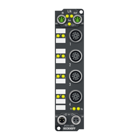
Fig. 6 EP3314-0002
Technical Data
Scope of Supply
Process Image
Fig. 7 TC Inputs Channel
5 Mounting and Connection
Mounting
Dimensions
Fig. 8 Dimensions
Fixing
Tightening Torques for Plug Connectors
Connection
Supply Voltages
Fig. 9 Connectors for Supply Voltages
Fig. 10 M8 Connector
Fig. 11 Status Leds for the Power Supply
Ethercat
Fig. 12 Ethercat Connector
Fig. 13 M8 Socket
Fig. 14 Ethercat Status Leds
Signal Connection
Fig. 15 Signal Connection - PT100 (RTD)
Fig. 16 Signal Connection - Thermocouple
Fig. 17 Status Leds at the Signal Connections
UL Requirements
Fig. 18 UL Label
ATEX Notes
ATEX - Special Conditions
BG2000 - Ethercat Box Protection Enclosures
Fig. 19 BG2000 - Putting the Cables
ATEX Documentation
Fig. 20 BG2000 - Fixing the Cables
Fig. 21 BG2000 - Mounting the Protection Enclosure
6 Commissioning/Configuration
Configuration in Twincat
EP3204 - Data Stream and Calculation of the Process Data
Vendor Calibration
Fig. 22 Resistance Measurement with a 4-Wire, 3-Wire and 2-Wire Connection Technique
Fig. 23 Data Flow: Resistance Measurement with a 2 and 4-Wire Connection Technique
Fig. 24 Resistance Measurement with a 4-Wire, 3-Wire and 2-Wire Connection Technique
Fig. 25 Data Flow: Resistance Measurement with a 3-Wire Connection Technique
User Calibration and Linearization
Fig. 26 Data Flow: User Compensation and Linearization
Scaling, Limits and Formatting
Fig. 27 Data Flow: User Scaling, Limit Evaluation, Error Bits and Formatting
Summary
Two-Point User Calibration
EP3204 - Object Overview
EP3204 - Object Description and Parameterization
Objects to be Parameterized During Commissioning
Objects for Regular Operation
Standard Objects (0X1000-0X1Fff)
Profile-Specific Objects (0X6000-0Xffff)
EP3314 - Object Overview
EP3314 - Object Description and Parameterization
Objects to be Parameterized During Commissioning
Objects for Regular Operation
Standard Objects (0X1000-0X1Fff)
Profile-Specific Objects (0X6000-0Xffff)
Restoring the Delivery State
Fig. 28 Selecting the Restore Default Parameters PDO
Fig. 29 Entering a Restore Value in the Set Value Dialog
7 Appendix
General Operating Conditions
Ethercat Box- / Ethercat P Box - Accessories
Support and Service
List of Illustrations
Advertisement
Quick Links
Download this manual
Documentation
EP3204 and EP3314
EtherCAT Box Modules for Pt100 (RTD) and for thermocouples
Version:
Date:
2.2
2019-11-05
Table of
Contents
Previous
Page
Next
Page
1
2
3
4
5
Advertisement
Chapters
Table of Contents
3
List of Illustrations
92
Table of Contents
Need help?
Do you have a question about the EP3204 and is the answer not in the manual?
Ask a question
Questions and answers
Related Manuals for Beckhoff EP3204
Control Unit Beckhoff EP3314 Documentation
Ethercat box modules for pt100 (rtd) and for thermocouples (92 pages)
Control Unit Beckhoff EP31 Series Documentation
Ethercat box modules with analog inputs (149 pages)
Control Unit Beckhoff EP3162 Documentation
Ethercat box modules with analog inputs (149 pages)
Control Unit Beckhoff EP3182 Documentation
Ethercat box modules with analog inputs (149 pages)
Control Unit Beckhoff EP5 Series Documentation
Ethercat box modules for angle and position measurement (133 pages)
Control Unit Beckhoff EP6001 Documentation
Serial interface modules (rs232 or rs422/rs485) (137 pages)
Control Unit Beckhoff EP6002 Documentation
Serial interface modules (rs232 or rs422/rs485) (137 pages)
Control Unit Beckhoff EP7211-0034 Documentation
Servomotor module with oct (147 pages)
Control Unit Beckhoff EP7041 Series Documentation
Stepper motor modules (134 pages)
Control Unit Beckhoff EPP3174 Documentation
Ethercat p box modules with configurable analog inputs (96 pages)
Control Unit Beckhoff EPP3184 Documentation
Ethercat p box modules with configurable analog inputs (96 pages)
Control Unit Beckhoff EP6224 Documentation
Io-link master with protection class ip67 (57 pages)
Control Unit Beckhoff EPI1 Series Manual
Io-link box modules with digital inputs (90 pages)
Control Unit Beckhoff EPI2 Series Documentation
Io-link-box modules with digital inputs (93 pages)
Control Unit Beckhoff EPP 7 Series Manual
Ethercat p box modules with id switch (25 pages)
Control Unit Beckhoff EPP3744 041 Series Manual
Ethercat p box modules with pressure inputs (65 pages)
This manual is also suitable for:
Ep3314
Table of Contents
Print
Rename the bookmark
Delete bookmark?
Delete from my manuals?
Login
Sign In
OR
Sign in with Facebook
Sign in with Google
Upload manual
Upload from disk
Upload from URL


Need help?
Do you have a question about the EP3204 and is the answer not in the manual?
Questions and answers