Table of Contents
Advertisement
Advertisement
Chapters
Table of Contents

Related Manuals for Beckhoff EP7041 Series


Summary of Contents for Beckhoff EP7041 Series
- Page 1 Documentation EP7041 Stepper motor modules Version: Date: 2019-10-15...
-
Page 3: Table Of Contents
Table of contents Table of contents 1 Foreword .............................. 5 Notes on the documentation...................... 5 Safety instructions .......................... 6 Documentation issue status ...................... 7 2 Product overview............................ 9 EtherCAT Box - Introduction...................... 9 Module overview.......................... 11 Introduction ............................ 12 2.3.1 EP7041-0002, EP7041 .................... 12 2.3.2 EP7041-2002........................ 13 2.3.3 EP7041-3002, EP7041-3102................... - Page 4 Table of contents General note on the introduction of the Beckhoff Identification Code (BIC) ........ 130 Support and Service ........................ 132 Version: 2.3 EP7041...
-
Page 5: Foreword
EP1590927, EP1789857, EP1456722, EP2137893, DE102015105702 with corresponding applications or registrations in various other countries. ® EtherCAT is registered trademark and patented technology, licensed by Beckhoff Automation GmbH, Germany. Copyright © Beckhoff Automation GmbH & Co. KG, Germany. The reproduction, distribution and utilization of this document as well as the communication of its contents to others without express authorization are prohibited. -
Page 6: Safety Instructions
All the components are supplied in particular hardware and software configurations appropriate for the application. Modifications to hardware or software configurations other than those described in the documentation are not permitted, and nullify the liability of Beckhoff Automation GmbH & Co. KG. Personnel qualification This description is only intended for trained specialists in control, automation and drive engineering who are familiar with the applicable national standards. -
Page 7: Documentation Issue Status
Foreword Documentation issue status Version Modifications • Technical data updated 2.2.0 • Update safety instructions • Update chapter Mounting 2.1.0 • EP7041-3102 added 2.0.0 • Migration 1.7.0 • Preface updated • Chapter on Nut torques for connectors updated • Chapter on EtherCAT connection updated •... - Page 8 1.1.0 1.0.0 Beckhoff Identification Code (BIC) The Beckhoff Identification Code contains additional information about the delivery state of the module: General note on the introduction of the Beckhoff Identification Code (BIC) [} 130]. Syntax of the batch number (D number) D: WW YY FF HH...
-
Page 9: Product Overview
Product overview Product overview EtherCAT Box - Introduction The EtherCAT system has been extended with EtherCAT Box modules with protection class IP 67. Through the integrated EtherCAT interface the modules can be connected directly to an EtherCAT network without an additional Coupler Box. The high-performance of EtherCAT is thus maintained into each module. The extremely low dimensions of only 126 x 30 x 26.5 mm (h x w x d) are identical to those of the Fieldbus Box extension modules. -
Page 10: Fig. 2 Ethercat Box With M8 Connections For Sensors/Actuators
EtherCAT, which is available for download from our website (www.beckhoff.com) under Downloads. EtherCAT XML Device Description You will find XML files (XML Device Description Files) for Beckhoff EtherCAT modules on our web- site (www.beckhoff.com) under Downloads, in the Configuration Files area. -
Page 11: Module Overview
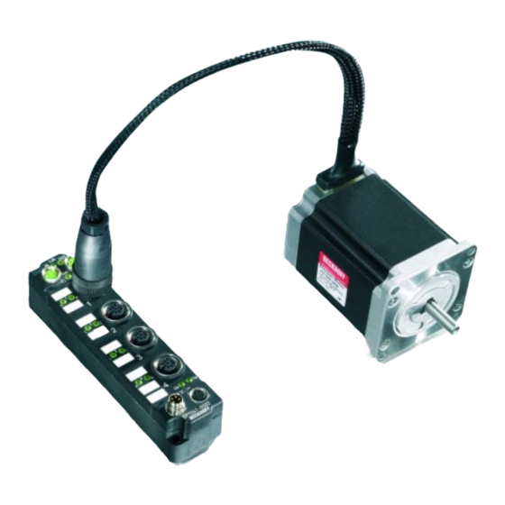
Product overview Module overview Fig. 4: EP7041 with stepper motor Module Output current for Integrated con- Comment stepper motor nection for mo- tor supply 2 x 3.5 A rated current, M12, female • Designed for particularly quiet and precise motor operation. EP7041-0002 [} 12] 2 x 5.0 A peak current 2 x 1.0 A rated current, M12, female... -
Page 12: Introduction
Product overview Introduction 2.3.1 EP7041-0002, EP7041 Fig. 5: EP7041-0002 Stepper Motor modules with interface for incremental encoder The EP7041-0002 and EP7041-1002 EtherCAT Box Modules are intended for the direct connection of different stepper motors. Two versions are available: • EP7041-0002: 2 x 3.5 A rated current, (2 x 5.0 A peak current) •... -
Page 13: Fig. 6 Ep7041-2002
Product overview 2.3.2 EP7041-2002 Fig. 6: EP7041-2002 Stepper Motor modules with interface for incremental encoder The EP7041-2002 EtherCAT Box is designed for direct connection of different stepper motors. The PWM output stages for two motor coils with compact design are located in the module together with two inputs for limit switches and cover a wide voltage and current range. -
Page 14: Ep7041-2002
Product overview 2.3.3 EP7041-3002, EP7041-3102 Fig. 7: EP7041-3002 and EP7041-3102 Stepper Motor modules with interface for incremental encoder The EP7041-3002 and EP7041-3102 EtherCAT Box Modules are designed for direct connection of different stepper motors. The PWM output stages for two motor coils with compact design are located in the module together with two inputs for limit switches and cover a wide voltage and current range. -
Page 15: Technical Data
Product overview Technical data All values are typical values at 25 °C, unless otherwise stated. Technical data EP7041-0002 EP7041-1002 EP7041-2002 EP7041-3002 EP7041-3102 Fieldbus Fieldbus EtherCAT Connection 2 x M8 socket, green Electrical isolation 500 V (fieldbus / IO) Process image Input: 2 x 16 bit data, 1 x 16 bit status Output: 2 x 16 bit data, 1 x 16 bit control Supply voltages Connection... -
Page 16: Scope Of Supply
Product overview Technical data EP7041-0002 EP7041-1002 EP7041-2002 EP7041-3002 EP7041-3102 Digital inputs: limit switch Number Connection M12 socket Signal voltage "0" -3 V ... 2 V Signal voltage "1" 3.5 V ... 28 V Input current 5 mA Digital output: Brake Number Connection M12 socket Output voltage 24 V from peripheral voltage U Output current 0.5 A, short-circuit proof Environmental conditions... -
Page 17: Ep7041 - Process Image
Product overview EP7041 - Process image The TwinCAT System Manager displays the EP7041 data in a tree structure. The tree shows • ENC Status compact: encoder status • STM Status: Stepper Motor Status • ENC Control compact: Encoder Control • STM Control: Stepper Motor Control •... - Page 18 Product overview STM Status The status information for the stepper motor can be found under STM Status. ENC Control compact The control parameters for the encoder can be found under ENC Control compact. STM Control The control parameters for the stepper motor can be found under STM Control.
- Page 19 Product overview STM Velocity The velocity settings for the stepper motor can be found under STM Velocity. EP7041 Version: 2.3...
-
Page 20: Installation
Installation Installation Mounting 3.1.1 Dimensions 26.5 13.5 Ø 3.5 Fig. 8: Dimensions All dimensions are given in millimeters. Housing features Housing material PA6 (polyamide) Sealing compound polyurethane Mounting two fastening holes Ø 3.5 mm for M3 Metal parts brass, nickel-plated Contacts CuZn, gold-plated Power feed through max. -
Page 21: Fixing
Mount the module with two M3 screws on the fastening holes in the corners of the module. The fastening holes have no thread. 3.1.3 Tightening torques for plug connectors Screw connectors tight with a torque wrench. (e.g. ZB8801 from Beckhoff) Connector diameter Tightening torque 0.4 Nm 0.6 Nm... -
Page 22: Connection
Plug Socket Feed-in Forwarding Fig. 10: M8 connector Contact Function Description Core color Control voltage Brown Peripheral voltage White GND to U Blue GND to U Black The core colors apply to cables of the type: Beckhoff ZK2020-xxxx-xxxx Version: 2.3 EP7041... -
Page 23: Fig. 11 Status Leds For The Power Supply
Installation 3.2.1.2 Status LEDs Fig. 11: Status LEDs for the power supply Display Meaning (control voltage) Supply voltage, U , is not present green illuminated Supply voltage, U , is present (peripheral voltage) Supply voltage, U , is not present green illuminated Supply voltage, U , is present 3.2.1.3... -
Page 24: Ethercat
Installation 3.2.2 EtherCAT 3.2.2.1 Connector EtherCAT Box Modules have two green M8 sockets for the incoming and downstream EtherCAT connections. Fig. 12: EtherCAT connector Connection Fig. 13: M8 socket EtherCAT Core colors connector Signal Contact ZB9010, ZB9020, ZB9030, ZB9032, ZB9031 and old versions of TIA-568B ZK1090-6292, ZB9030, ZB9032, ZK1090-3xxx-... -
Page 25: Fig. 14 Ethercat Status Leds
(CAT5) according to EN 50173 or ISO/IEC 11801 should be used. EtherCAT uses four wires for signal transmission. Thanks to automatic line detection ("Auto MDI-X"), both symmetrical (1:1) or cross-over cables can be used between Beckhoff EtherCAT. Detailed recommendations for the cabling of EtherCAT devices EP7041... -
Page 26: Stepper Motor, Brake, Encoder
Installation 3.2.3 Stepper motor, brake, encoder 3.2.3.1 Signal connection Fig. 15: Signal connection EP7041-3002 NOTE Note the numbering of the M12 sockets Mixing up the M12 connectors can damage the module. M12 socket no. 1: Stepper motor connection Fig. 16: Stepper motor connection Version: 2.3 EP7041... -
Page 27: Fig. 17 Connection For Motor Supply With Ep7041-0002 And Ep7041-1002
Installation M12-Socket no. 2: Connection for motor supply NOTE The motor supply connection is not protected against polarity reversal Defect possible through polarity reversal. • Ensure that the polarity is correct. Fig. 17: Connection for motor supply with EP7041-0002 [} 12] and EP7041-1002 [} 12] Fig. 18: Connection for motor supply with EP7041-2002 [} 13] and EP7041-3002 [} 14] M12 socket no. 3: Connection for digital inputs and outputs The signal connection of the digital inputs and outputs is done via M12 connectors. -
Page 28: Fig. 20 Encoder Connection
Installation M12 socket no. 4: Encoder connection NOTE The encoder supply voltage is not short-circuit proof. Risk of damage due to short circuit. • Avoid short-circuiting the encoder supply voltage "V Enc“. Encoder Fig. 20: Encoder connection Version: 2.3 EP7041... -
Page 29: Fig. 21 Leds Ep7041-3002
Installation 3.2.3.2 Status LEDs Fig. 21: LEDs EP7041-3002 Status LEDs at the M12 connections Connection Display Meaning M12 socket no. 1: green Motor control is enabled (Index 0x6010:02 [} 95] is set) and EP7041 is ready to operate Stepper motor left yellow If motor is disabled: motor control in standby If motor is enabled: warning, configuration error. -
Page 30: Atex Notes
Installation ATEX notes 3.3.1 ATEX - Special conditions WARNING Observe the special conditions for the intended use of EtherCAT Box modules in poten- tially explosive areas – directive 94/9/EU. • The certified components are to be installed with a BG2000-0000 or BG2000-0010 protection enclosure [} 31] that guarantees a protection against mechanical hazards! •... -
Page 31: Bg2000 - Ethercat Box Protection Enclosures
Installation 3.3.2 BG2000 - EtherCAT Box protection enclosures WARNING Risk of electric shock and damage of device! Bring the EtherCAT system into a safe, powered down state before starting installation, disassembly or wiring of the modules! ATEX WARNING Mount a protection enclosure! To fulfill the special conditions according to ATEX [} 30], a BG2000-0000 or BG2000-0010 protection enclo- sure has to be mounted over the EtherCAT Box. -
Page 32: Atex Documentation
Notes about operation of EtherCAT Box Modules (EPxxxx-xxxx) in potentially explo- sive areas (ATEX) Pay also attention to the continuative documentationNotes about operation of EtherCAT Box Mod- ules (EPxxxx-xxxx) in potentially explosive areas (ATEX) that is available in the download area of the Beckhoff homepage http:\\www.beckhoff.com! Version: 2.3 EP7041... -
Page 33: Commissioning/Configuration
Beckhoff website (http://www.beckhoff.de/english/download/elconfg.htm? id=1983920606140) and installed according to the installation instructions. At the Beckhoff TwinCAT System Manager the configuration tree can be build in two different ways: • by scanning [} 33] for existing hardware (called "online") and •... -
Page 34: Fig. 26 Appending A New I/O Device (I/O Devices -> Right-Click -> Append Device
Commissioning/Configuration Fig. 26: Appending a new I/O device (I/O Devices -> right-click -> Append Device...) Fig. 27: Selecting the device EtherCAT • Append a new box. Fig. 28: Appending a new box (Device -> right-click -> Append Box...) • In the dialog that appears select the desired box (e.g. EP2816-0008), and confirm with OK. Version: 2.3 EP7041... -
Page 35: Fig. 29 Selecting A Box (E.g. Ep2816-0008)
Commissioning/Configuration Fig. 29: Selecting a Box (e.g. EP2816-0008) Fig. 30: Appended Box in the TwinCAT tree EP7041 Version: 2.3... -
Page 36: Configuration Via Twincat
Commissioning/Configuration 4.1.2 Configuration via TwinCAT In the left-hand window of the TwinCAT System Manager, click on the branch of the EtherCAT Box you wish to configure (EP2816-0008 in this example). Fig. 31: Branch of the EtherCAT box to be configured In the right-hand window of the TwinCAT System manager, various tabs are now available for configuring the EtherCAT Box. -
Page 37: Fig. 33 Ethercat Tab
Commissioning/Configuration EtherCAT tab Fig. 33: EtherCAT tab Type EtherCAT device type Product/Revision Product and revision number of the EtherCAT device Auto Inc Addr. Auto increment address of the EtherCAT device. The auto increment address can be used for addressing each EtherCAT device in the communication ring through its physical position. -
Page 38: Fig. 34 Process Data Tab
Commissioning/Configuration Fig. 34: Process Data tab Sync Manager Lists the configuration of the Sync Manager (SM). If the EtherCAT device has a mailbox, SM0 is used for the mailbox output (MbxOut) and SM1 for the mailbox input (MbxIn). SM2 is used for the output process data (outputs) and SM3 (inputs) for the input process data. If an input is selected, the corresponding PDO assignment is displayed in the PDO Assignment list below. - Page 39 Commissioning/Configuration Activation of PDO assignment • the EtherCAT slave has to run through the PS status transition cycle (from pre-operational to safe-operational) once (see Online tab [} 42]), • and the System Manager has to reload the EtherCAT slaves ( button) PDO list List of all PDOs supported by this EtherCAT device.
-
Page 40: Fig. 35 Startup Tab
Commissioning/Configuration Fig. 35: Startup tab Column Description Transition Transition to which the request is sent. This can either be • the transition from pre-operational to safe-operational (PS), or • the transition from safe-operational to operational (SO). If the transition is enclosed in "<>" (e.g. <PS>), the mailbox request is fixed and cannot be modified or deleted by the user. -
Page 41: Fig. 36 Coe - Online Tab
Commissioning/Configuration Fig. 36: CoE - Online tab Object list display Column Description Index Index and subindex of the object Name Name of the object Flags The object can be read, and data can be written to the object (read/write) The object can be read, but no data can be written to the object (read only) An additional P identifies the object as a process data object. -
Page 42: Fig. 37 Advanced Settings
Commissioning/Configuration Fig. 37: Advanced settings Online If this option button is selected, the list of the objects included in the object - via SDO information directory of the slave is uploaded from the slave via SDO information. The list below can be used to specify which object types are to be uploaded. Offline If this option button is selected, the list of the objects included in the object - via EDS file... - Page 43 Commissioning/Configuration State Machine Init This button attempts to set the EtherCAT device to the Init state. Pre-Op This button attempts to set the EtherCAT device to the pre-operational state. This button attempts to set the EtherCAT device to the operational state. Bootstrap This button attempts to set the EtherCAT device to the Bootstrap state.
-
Page 44: Integration Into The Nc Configuration
Installation of the latest XML device description Please ensure that you have installed the corresponding latest XML device description in TwinCAT. This can be downloaded from the Beckhoff website (http://www.beckhoff.de/german/default.htm? download/elconfg.htm) and installed according to the installation instructions. Integration into the NC can be accomplished as follows: •... -
Page 45: Fig. 41 Selecting And Confirming The Axis Type
Commissioning/Configuration Fig. 41: Selecting and confirming the axis type • Left-click your axis to select it. Under the Settings tab select "Link To..." (see Fig. Linking the axis with the terminal). Fig. 42: Linking the axis with the terminal • Select the right terminal (Stepper Drive (MDP 703)) and confirm with OK. Fig. 43: Selecting the right terminal •... -
Page 46: Fig. 44 Automatic Linking Of All Main Variables
Commissioning/Configuration Fig. 44: Automatic linking of all main variables • Several parameters have to be set before the motor can be started up. The values can be found in section "Configuration of the main parameters [} 48]". Please set these parameters before continuing with the motor commissioning procedure. -
Page 47: Fig. 45 Enabling An Axis
Commissioning/Configuration Fig. 45: Enabling an axis You can now move the axis with the function keys F1, F2 (Backward) or F3, F4 (Forward). Alternatively you can control the axis via the Functions tab. Example • Select as Reversing Sequence as the start mode. •... -
Page 48: Configuration Of The Main Parameters
Commissioning/Configuration Fig. 46: Axis control, "Functions" tab The motor now travels to Position 1, remains there for 1 s and then returns to Position 2. This is repeated until you click Stop. 4.1.4 Configuration of the main parameters The data specified here apply to an AS 1050-0120 stepper motor and are intended as an example. For other motors the values may vary, depending on the application. -
Page 49: Fig. 47 Adaptation Of Current And Voltage
Commissioning/Configuration Reduced current can be set in index 0x8010:02 [} 78]. This reduces the coil current when at a standstill (and therefore the power dissipation). Please note that the torque is also reduced. Fig. 47: Adaptation of current and voltage Base frequency selection Microstepping is set to 1/64 and cannot be changed. -
Page 50: Fig. 49 Selecting The Feedback System
Commissioning/Configuration Setting the feedback type By default, the stepper module is set to internal counter. If an external encoder is used, the setting must be changed by double-clicking on the index 0x8012:08 [} 79] Feedback type in the Enum menu (Fig. Selecting the feedback system). Fig. 49: Selecting the feedback system factor (EP7041-0002 [} 12] and EP7041-1002 [} 12]only) The K... -
Page 51: Fig. 50 Speed Ramps
Commissioning/Configuration Fig. 50: Speed ramps This value can be set in index 0x8011:07 [} 78] Ka factor (curr.) (see fig. Setting the K factor). Fig. 51: Setting the K factor NC settings Reference speed selection The maximum speed can be calculated from the base frequency and the motor frequency. = base frequency / motor frequency = (2000 full steps / s) / (200 full steps / rev) = 10 revolutions / s The reference speed can be calculated by multiplying the maximum speed with the distance per revolution. -
Page 52: Fig. 52 Reference Speed Parameter
Commissioning/Configuration Fig. 52: Reference speed parameter Dead time compensation The dead time compensation should theoretically be 3 cycles of the NC cycle time, although in practice 4 cycles are preferable. At a cycle time of 2 ms it should therefore be 0.008 s. The dead time compensation can be found under Advanced Settings in the encoder parameters. -
Page 53: Fig. 54 Setting The Scaling Factor (Example With Encoder)
Commissioning/Configuration Fig. 54: Setting the scaling factor (example with encoder) Calculation of the scaling factor with encoder: SF = distance per revolution / increments x 4 = 360° / 1024 x 4 = 0.087890625 mm / INC without encoder: SF = distance per revolution / full steps x microsteps = 360° / 200 x 64 = 0.028125 mm / INC Position lag monitoring The position lag monitoring function checks whether the current position lag of an axis has exceeded the limit value. -
Page 54: Fig. 55 Position Lag Monitoring Parameters
Commissioning/Configuration Fig. 55: Position lag monitoring parameters factors (only with external encoder) In the NC two proportional factors K can be set under Axis 1_Ctrl on the Parameter tab. First select the position controller Type with two P constants (with KA) under the NC Controller tab. The two P constants are for the Standstill range and for the Moving range (see Fig. -
Page 55: Fig. 57 Setting The Proportional Factor Kv
Commissioning/Configuration Fig. 57: Setting the proportional factor K Dead band for position errors Microstepping can be used to target 200 x 64 = 12800 positions. Since the encoder can only scan 1024 x 4 = 4096 positions, positions between two encoder scan points may not be picked up correctly, in which case the terminal will control around this position. The dead band for position errors is a tolerance range within which the position is regarded as "reached"... -
Page 56: Basic Principles For The Positioning Interface
Commissioning/Configuration Fig. 59: Setting the acceleration time 4.1.5 Basic principles for the Positioning Interface The Positioning interface offers the user a possibility to implement travel commands directly on the terminal. 4.1.5.1 Predefined PDO Assignment The "Predefined PDO Assignment" enables a simplified selection of the process data. Select the function "Positioning interface"... -
Page 57: Fig. 61 Settings Objects In The Coe
Commissioning/Configuration Fig. 61: Settings objects in the CoE POS Settings: Velocity min.: For reasons of performance when ramping down to the target position, the terminal needs a safety margin of 0.5%. That means that, depending on the maximum velocity reached and the configured deceleration, the time is calculated at which the deceleration ramp begins. - Page 58 Commissioning/Configuration Emergency deceleration: Emergency deceleration time (both directions of rotation). If “Emergency stop” is set in the appropriate PDO, the motor is stopped within this time. Calibration position: The current counter value is loaded with this value after calibration. Calibration velocity (towards plc cam): Velocity with which the motor travels towards the cam during calibration.
-
Page 59: Fig. 62 Diagnostic Objects In The Coe
Commissioning/Configuration Fig. 62: Diagnostic objects in the CoE POS Info data: Status word: The "Status word" reflects the status bits used in Index 0xA020 in a data word, in order to be able to process them more simply in the PLC. The positions of the bits correspond to the number of the subindex-1. Bit 0: Command rejected Bit 1: Command aborded Bit 2: Target overrun... - Page 60 Commissioning/Configuration Name Description INIT 0x0000 Initialization/preparation for the next travel command. IDLE 0x0001 Wait for the next travel command. START 0x0010 The new command is evaluated and the corresponding calculations are performed. ACCEL 0x0011 Acceleration phase. CONST 0x0012 Constant phase DECEL 0x0013 Deceleration phase EMCY...
-
Page 61: Fig. 63 Flow Diagram For A Travel Command
Commissioning/Configuration Fig. 63: Flow diagram for a travel command 4.1.5.6 Start types The Positioning interface offers different types of positioning. The following table contains all commands supported; these are divided into 4 groups. EP7041 Version: 2.3... -
Page 62: Fig. 64 Absolute Positioning
Commissioning/Configuration Name Command Group Description ABSOLUTE 0x0001 Absolute positioning to a specified target position Standard [} 62] RELATIVE 0x0002 Relative positioning to a calculated target position; a specified posi- tion difference is added to the current position ENDLESS_PLUS 0x0003 Endless travel in the positive direction of rotation (direct specification of a speed) ENDLESS_MINUS 0x0004... -
Page 63: Fig. 65 Relative Positioning
Commissioning/Configuration Fig. 65: Relative positioning ENDLESS_PLUS / ENDLESS_MINUS The two start types ENDLESS_PLUS and ENDLESS_MINUS offer the possibility in the Positioning Interface to specify a direct motor velocity in order to travel endlessly in the positive or negative direction with the specified accelerations. -
Page 64: Fig. 68 Calibration With Cam
Commissioning/Configuration NOTE Caution when using the RELATIVE_CHANGE positioning The change by means of RELATIVE_CHANGE must be used with caution, since the current position of the motor is also used here as the start position. Due to propagation delays in the system, the position indi- cated in the PDO never corresponds to the actual position of the motor! Therefore a difference to the de- sired target position always results in the calculation of the transferred position delta. - Page 65 Commissioning/Configuration If calibration by hardware is not possible due to the circumstances of the application, the user can also set the Calibrated bit manually or automatically. The manual setting or deletion takes place with the commands SET_CALIBRATION and CLEAR_CALIBRATION. It is simpler, however, if the standard start types (Index 0x8021:01) are set to SET_CALIBRATION_AUTO. The Calibrated bit will now be set automatically by the first rising edge on Enable.
-
Page 66: Fig. 70 Effect Of The Modulo Tolerance Window - Modulo Target Position 0° In Positive Direction
Commissioning/Configuration Fig. 70: Effect of the modulo tolerance window - modulo target position 0° in positive direction Example An axis is positioned to 0°, with the result that subsequently the actual position of the axis is exactly 0°. A further modulo travel command to 360° in positive direction results in a full turn, with the subsequent modulo position of the axis of once again being exactly 0°. - Page 67 Commissioning/Configuration identically, as long the actual position is between 359° and 1°. If the position exceeds 0° by less than 1°, the axis is re-positioned in positive direction at a modulo start. In both cases, a target position of 0° therefore leads to minimum movement to exactly 0°.
- Page 68 Commissioning/Configuration Modulo start type Absolute start Modulo tar- Relative Absolute Modulo end Note position get position travel path end posi- position tion MODULO_PLUS 90.00° 90.00° 0.00° 90.00° 90.00° MODULO_PLUS 90.90° 90.00° -0.90° 90.00° 90.00° MODULO_PLUS 91.10° 90.00° 358.90° 450.00° 90.00° outside TF MODULO_PLUS 89.10°...
-
Page 69: Fig. 71 Scope Recording Without Overrunning The Target Position
Commissioning/Configuration 4.1.5.8 Examples of two travel commands with a dynamic change of the target position Without overrun of the target position Time POS Outputs POS Inputs Description Execute = 1 Busy = 1 • Specification of the first parameter Target position = 200000 Accelerate = 1 •... -
Page 70: Fig. 72 Scope Recording With Overrunning Of The Final Target Position
Commissioning/Configuration With overrun of the target position Time POS Outputs POS Inputs Description Execute = 1 Busy = 1 • Specification of the 1 parameter Target position = 200000 Accelerate = 1 • Start of the 1 acceleration phase Velocity = 5000 Start type = 0x0001 Acceleration = 3000 Deceleration = 5000... -
Page 71: Application Example
EtherCAT XML Device Description The display matches that of the CoE objects from the EtherCAT XML Device Description. We rec- ommend downloading the latest XML file from the download area of the Beckhoff website and in- stalling it according to installation instructions. -
Page 72: Fig. 74 Selecting The Mac Address
Commissioning/Configuration Fig. 74: Selecting the MAC address • In the PLC configuration you have to adjust the path for the PLC program. Click on the appended PLC program and select the tab IEC1131 (see Fig. Changing the PLC path). Select Change and enter the correct path. -
Page 73: Fig. 76 Required Libraries
Commissioning/Configuration Fig. 76: Required libraries Once this is done, certain global variables are declared (see Fig. Global variables). The data types PLCTONC_AXLESTRUCT and NCTOPLC_AXLESTRUCT deal with the communication between the PLC and the NC. Fig. 77: Global variables Once the global variables have been declared, programming can commence. Start with declaring local variables (see Fig. -
Page 74: Fig. 79 Program Code
Commissioning/Configuration Fig. 79: Program code The motor can then be operated with the aid of the following visualization (see Fig. Visualization). Press Enable to enable the axis. In "Free run mode" you can now use the Left or Right buttons, and the motor will run with a speed defined under fbMoveVelocity_Axis_1 in the selected direction. -
Page 75: Fig. 80 Visualization
Commissioning/Configuration Fig. 80: Visualization Information on function blocks and data types Further information on the function blocks and data types used can be found in the Beckhoff Infor- mation System. EP7041 Version: 2.3... -
Page 76: Restoring The Delivery State
Commissioning/Configuration 4.1.7 Restoring the delivery state To restore the delivery state for backup objects in ELxxxx terminals / EPxxxx- and EPPxxxx boxes, the CoE object Restore default parameters, SubIndex 001 can be selected in the TwinCAT System Manager (Config mode). Fig. 81: Selecting the Restore default parameters PDO Double-click on SubIndex 001 to enter the Set Value dialog. -
Page 77: Coe Objects Ep7041-0002, Ep7041-1002, Ep7041-2002
EtherCAT XML Device Description The display matches that of the CoE objects from the EtherCAT XML Device Description. We rec- ommend downloading the latest XML file from the download area of the Beckhoff website and in- stalling it according to installation instructions. - Page 78 Commissioning/Configuration 4.2.1.1 Objects for commissioning Index 1011 Restore default parameters Index (hex) Name Meaning Data type Flags Default 1011:0 Restore default pa- Restore default parameters UINT8 0x01 (1 rameters 1011:01 SubIndex 001 If this object is set to "0x64616F6C" in the set value dia- UINT32 0x00000000 log, all backup objects are reset to their delivery state.
- Page 79 Commissioning/Configuration Index 8012 STM Features Ch.1 Index (hex) Name Meaning Data type Flags Default 8012:0 STM Features Ch.1 Maximum subindex UINT8 0x36 (54 8012:01 Operation mode Operation mode (currently only direct velocity is sup- BIT4 0x01 (1 ported) Automatic Direct velocity Velocity controller Position controller 8012:05...
- Page 80 Commissioning/Configuration Index (hex) Name Meaning Data type Flags Default 8012:19 Select info data 2 Selection "Info data 2" UINT8 0x04 (4 Status word Motor voltage coil A (unit 1 mV) Motor voltage coil B (unit 1 mV) Motor current coil A (unit 1 mA) Motor current coil B (unit 1 mA) Duty cycle coil A (unit 1%) Duty cycle coil B (unit 1%)
- Page 81 Commissioning/Configuration Index 8020 POS Settings Ch.1 Index (hex) Name Meaning Data type Flags Default 8020:0 POS Settings Ch.1 Maximum subindex UINT8 0x10(16 8020:01 Velocity min. Minimum set velocity (range: 0-10000) INT16 0x0064 (100 8020:02 Velocity max. Maximum set velocity (range: 0-10000) INT16 0x2710 (10000...
- Page 82 Commissioning/Configuration Index 8021 POS Features Ch.1 Index Name Meaning Data type Flags Default value 8021:0 POS Features Ch.1 Maximum subindex UINT8 0x16 (22 8021:01 Start type permitted values: UINT16 0x0001 (1 0: Idle 1: Absolute 2: Relative 3: Endless plus 4: Endless minus 6: Additive 24832: Calibration (Hardware sync)
- Page 83 Commissioning/Configuration 4.2.1.2 Standardobjekte (0x1000 .. 0x1FFF) The standard objects have the same meaning for all EtherCAT slaves. Index 1000 Device type Index (hex) Name Meaning Data type Flags Default 1000:0 Device type Device type of the EtherCAT slave: The Lo-Word con- UINT32 0x00001389 tains the CoE profile used (5001).
- Page 84 Commissioning/Configuration Index 10F3 Diagnosis History Index (hex) Name Meaning Data type Flags Default 10F3:0 Diagnosis History Maximum Subindex UINT8 0x37 (55 10F3:01 Maximum Messages Maximum number of stored messages. A maximum of UINT8 0x00 (0 50 messages can be stored. 10F3:02 Newest Message Subindex of the latest message...
- Page 85 Commissioning/Configuration Index 1405 POS RxPDO-Par Control compact Index (hex) Name Meaning Data type Flags Default 1405:0 POS RxPDO-Par PDO Parameter RxPDO 6 UINT8 0x06 (6 Control compact 1405:06 Exclude RxPDOs Specifies the RxPDOs (index of RxPDO mapping ob- OCTET- 03 16 04 16 jects) that must not be transferred together with RxPDO STRING[6] 06 16...
- Page 86 Commissioning/Configuration Index 1602 STM RxPDO-Map Control Index (hex) Name Meaning Data type Flags Default 1602:0 STM RxPDO-Map PDO Mapping RxPDO 3 UINT8 0x07 (7 Control 1602:01 SubIndex 001 1. PDO Mapping entry (object 0x7010 (STM Outputs UINT32 0x7010:01, 1 Ch.1), entry 0x01 (Enable)) 1602:02 SubIndex 002 2.
- Page 87 Commissioning/Configuration Index 1606 POS RxPDO-Map Control Index (hex) Name Meaning Data type Flags Default 1606:0 POS RxPDO-Map PDO Mapping RxPDO 7 UINT8 0x09 (9 Control 1606:01 SubIndex 001 1. PDO Mapping entry (object 0x7020 (POS Outputs UINT32 0x7020:01, 1 Ch.1), entry 0x01 (Execute)) 1606:02 SubIndex 002 2.
- Page 88 Commissioning/Configuration Index 1805 POS TxPDO-Par Status compact Index (hex) Name Meaning Data type Flags Default 1805:0 POS TxPDO-Par Sta- PDO Parameter TxPDO 7 UINT8 0x06 (6 tus compact 1805:06 Exclude TxPDOs Specifies the RxPDOs (index of RxPDO mapping ob- OCTET- 06 1A jects) that must not be transferred together with RxPDO STRING[2]...
- Page 89 Commissioning/Configuration Index 1A01 ENC TxPDO-Map Status Index (hex) Name Meaning Data type Flags Default 1A01:0 ENC TxPDO-Map PDO Mapping TxPDO 2 UINT8 0x11 (17 Status 1A01:01 SubIndex 001 1. PDO Mapping entry (object 0x6000 (ENC Inputs UINT32 0x6000:01, 1 Ch.1), entry 0x01 (Latch C valid)) 1A01:02 SubIndex 002 2.
- Page 90 Commissioning/Configuration Index 1A03 STM TxPDO-Map Status Index (hex) Name Meaning Data type Flags Default 1A03:0 STM TxPDO-Map PDO Mapping TxPDO 4 UINT8 0x0E (14 Status 1A03:01 SubIndex 001 1. PDO Mapping entry (object 0x6010 (STM Inputs UINT32 0x6010:01, 1 Ch.1), entry 0x01 (Ready to enable)) 1A03:02 SubIndex 002 2.
- Page 91 Commissioning/Configuration Index 1A06 POS TxPDO-Map Status Index (hex) Name Meaning Data type Flags Default 1A06:0 POS TxPDO-Map PDO Mapping TxPDO 7 UINT8 0x09 (9 Status compact 1A06:01 SubIndex 001 1. PDO Mapping entry (object 0x6020 (POS Inputs UINT32 0x6020:01, 1 Ch.1), entry 0x01 (Busy)) 1A06:02 SubIndex 002...
- Page 92 Commissioning/Configuration Index 1C12 RxPDO assign Index (hex) Name Meaning Data type Flags Default 1C12:0 RxPDO assign PDO Assign Outputs UINT8 0x03 (3 1C12:01 Subindex 001 1. allocated RxPDO (contains the index of the associated UINT16 0x1600 RxPDO mapping object) (5632 1C12:02 Subindex 002 2.
- Page 93 Commissioning/Configuration Index 1C32 SM output parameter Index (hex) Name Meaning Data type Flags Default 1C32:0 SM output parameter Synchronization parameters for the outputs UINT8 0x20 (32 1C32:01 Sync mode Current synchronization mode: UINT16 0x0001 (1 • 0: Free Run • 1: Synchron with SM 2 Event •...
- Page 94 Commissioning/Configuration Index 1C33 SM input parameter Index (hex) Name Meaning Data type Flags Default 1C33:0 SM input parameter Synchronization parameters for the inputs UINT8 0x20 (32 1C33:01 Sync mode Current synchronization mode: UINT16 0x0022 (34 • 0: Free Run • 1: Synchronous with SM 3 Event (no outputs available) •...
- Page 95 Commissioning/Configuration 4.2.1.3 Profile-specific objects (0x6000 .. 0xFFFF) The profile-specific objects have the same meaning for all EtherCAT slaves that support the profile 5001. Index 6000 ENC Inputs Ch.1 Index (hex) Name Meaning Data type Flags Default 6000:0 ENC Inputs Ch.1 Maximum subindex UINT8 0x16 (22...
- Page 96 Commissioning/Configuration Index 6020 POS Inputs Ch.1 Index (hex) Name Meaning Data type Flags Default 6020:0 POS Inputs Ch.1 Maximum subindex UINT8 0x22 (34 6020:01 Busy A current travel command is active BOOLEAN 0x00 (0 6020:02 In-Target Motor has arrived at target BOOLEAN 0x00 (0 6020:03...
- Page 97 Commissioning/Configuration Index 7020 POS Outputs Ch.1 EP7041 Version: 2.3...
- Page 98 Commissioning/Configuration Index (hex) Name Meaning Data type Flags Default 7020:0 POS Outputs Ch.1 Maximum subindex UINT8 0x24 (36 7020:01 Execute Start travel command (rising edge), or prematurely abort BOOLEAN 0x00 (0 travel command (falling edge) 7020:02 Emergency Stop Prematurely abort travel command with an emergency BOOLEAN 0x00 (0 ramp (rising edge)
- Page 99 Commissioning/Configuration Index (hex) Name Meaning Data type Flags Default 0x6E00 Calibration, Set calibration set manual manually 0x6E01 Calibration, Set calibration au- set manual tomatically auto 0x6F00 Calibration, Clear calibration clear manual manually 7020:23 Acceleration Acceleration specification UINT16 0x0000 (0 7020:24 Deceleration Deceleration specification UINT16...
- Page 100 Commissioning/Configuration Index 9010 STM Info data Ch.1 Index (hex) Name Meaning Data type Flags Default 9010:0 STM Info data Ch.1 Maximum subindex UINT8 0x08 (8 9010:01 Status word UINT16 0x0000 (0 Status word (see index 0xA010 [} 101]) 9010:02 Motor coil voltage A Motor voltage coil A (unit 1 mV) UINT16 0x0000 (0...
- Page 101 Commissioning/Configuration Index A010 STM Diag data Ch.1 Index (hex) Name Meaning Data type Flags Default A010:0 STM Diag data Ch.1 Maximum subindex UINT8 0x11 (17 A010:01 Saturated Driver stage operates with maximum duty cycle BOOLEAN 0x00 (0 A010:02 Over temperature Internal terminal temperature is higher than 80°C (see BOOLEAN 0x00 (0...
- Page 102 Commissioning/Configuration Index F80F STM Vendor data Index (hex) Name Meaning Data type Flags Default F80F:0 STM Vendor data Maximum subindex UINT8 0x08 (8 F80F:01 PWM Frequency DC link frequency (unit: 1 Hz) UINT16 0x7530 (30000 F80F:02 Deadtime Dead time for pulse width modulation UINT16 0x0102 (258...
-
Page 103: Coe Objects Ep7041-3002, Ep7041-3102
EtherCAT XML Device Description The display matches that of the CoE objects from the EtherCAT XML Device Description. We rec- ommend downloading the latest XML file from the download area of the Beckhoff website and in- stalling it according to installation instructions. - Page 104 Commissioning/Configuration 4.3.1.1 Objects for commissioning Index 1011 Restore default parameters Index (hex) Name Meaning Data type Flags Default 1011:0 Restore default pa- Restore default parameters UINT8 0x01 (1 rameters 1011:01 SubIndex 001 If this object is set to "0x64616F6C" in the set value dia- UINT32 0x00000000 log, all backup objects are reset to their delivery state.
- Page 105 Commissioning/Configuration Index 8012 STM Features Ch.1 Index (hex) Name Meaning Data type Flags Default 8012:0 STM Features Ch.1 Maximum subindex UINT8 0x45 (69 8012:01 Operation mode Operation mode (currently only direct velocity is sup- BIT4 0x00 (0 ported) Automatic Direct velocity Velocity controller Position controller 8012:05...
- Page 106 Commissioning/Configuration Index 8012 STM Features Ch.1 Index (hex) Name Meaning Data type Flags Default 8012:19 Select info data 2 UINT8 0x09 (9 Selection "Info data 2" (see 0x8012:11 [} 105]) 8012:30 Invert digital input 1 Inversion of digital input 1 BOOLEAN 0x00 (0 8012:31 Invert digital input 2...
- Page 107 Commissioning/Configuration Index 8014 STM Motor Features Ch.1 Index (hex) Name Meaning Data type Flags Default 8014:0 STM Motor Features Maximum subindex UINT8 0x31 (49 Ch.1 8014:01 Chopper: Mode BIT2 0x00 (0 8014:03 Chopper: Off time BIT4 0x05 (5 8014:07 Chopper: Comparator BOOLEAN 0x00 (0 disabled...
- Page 108 Commissioning/Configuration Index 8021 POS Features Ch.1 Index (hex) Name Meaning Data type Flags Default 8021:0 POS Features Ch.1 Maximum subindex UINT8 0x14 (20 8021:01 Start type Standard start type UINT16 0x0001 (1 8021:11 Time information Time information in subindex 0x6pp0:22 ("Actual drive BIT2 0x00 (0 time")
- Page 109 Commissioning/Configuration 4.3.1.2 Standard objects (0x1000 .. 0x1FFF) The standard objects have the same meaning for all EtherCAT slaves. Index 1000 Device type Index (hex) Name Meaning Data type Flags Default 1000:0 Device type Device type of the EtherCAT slave: The Lo-Word con- UINT32 0x00001389 tains the CoE profile used (5001).
- Page 110 Commissioning/Configuration Index 10F3 Diagnosis History Index (hex) Name Meaning Data type Flags Default 10F3:0 Diagnosis History Maximum Subindex UINT8 0x37 (55 10F3:01 Maximum Messages Maximum number of stored messages. A maximum of UINT8 0x00 (0 50 messages can be stored. 10F3:02 Newest Message Subindex of the latest message...
- Page 111 Commissioning/Configuration Index 1405 POS RxPDO-Par Control compact Index (hex) Name Meaning Data type Flags Default 1405:0 POS RxPDO-Par PDO Parameter RxPDO 6 UINT8 0x06 (6 Control compact 1405:06 Exclude RxPDOs Specifies the RxPDOs (index of RxPDO mapping ob- OCTET- 03 16 04 16 jects) that must not be transferred together with RxPDO STRING[6] 06 16...
- Page 112 Commissioning/Configuration Index 1602 STM RxPDO-Map Control Index (hex) Name Meaning Data type Flags Default 1602:0 STM RxPDO-Map PDO Mapping RxPDO 3 UINT8 0x07 (7 Control 1602:01 SubIndex 001 1. PDO Mapping entry (object 0x7010 (STM Outputs UINT32 0x7010:01, 1 Ch.1), entry 0x01 (Enable)) 1602:02 SubIndex 002 2.
- Page 113 Commissioning/Configuration Index 1606 POS RxPDO-Map Control Index (hex) Name Meaning Data type Flags Default 1606:0 POS RxPDO-Map PDO Mapping RxPDO 7 UINT8 0x09 (9 Control 1606:01 SubIndex 001 1. PDO Mapping entry (object 0x7020 (POS Outputs UINT32 0x7020:01, 1 Ch.1), entry 0x01 (Execute)) 1606:02 SubIndex 002 2.
- Page 114 Commissioning/Configuration Index 1807 POS TxPDO-Par Status Index (hex) Name Meaning Data type Flags Default 1807:0 POS TxPDO-Par Sta- PDO parameter TxPDO 8 UINT8 0x06 (6 1807:06 Exclude TxPDOs Specifies the TxPDOs (index of TxPDO mapping objects) OCTET- 06 1A that must not be transferred together with TxPDO 8 STRING[2] Index 1A00 ENC TxPDO-Map Status compact Index (hex) Name...
- Page 115 Commissioning/Configuration Index 1A01 ENC TxPDO-Map Status Index (hex) Name Meaning Data type Flags Default 1A01:0 ENC TxPDO-Map PDO Mapping TxPDO 2 UINT8 0x11 (17 Status 1A01:01 SubIndex 001 1. PDO Mapping entry (object 0x6000 (ENC Inputs UINT32 0x6000:01, 1 Ch.1), entry 0x01 (Latch C valid)) 1A01:02 SubIndex 002 2.
- Page 116 Commissioning/Configuration Index 1A03 STM TxPDO-Map Status Index (hex) Name Meaning Data type Flags Default 1A03:0 STM TxPDO-Map PDO Mapping TxPDO 4 UINT8 0x0E (14 Status 1A03:01 SubIndex 001 1. PDO Mapping entry (object 0x6010 (STM Inputs UINT32 0x6010:01, 1 Ch.1), entry 0x01 (Ready to enable)) 1A03:02 SubIndex 002 2.
- Page 117 Commissioning/Configuration Index 1A06 POS TxPDO-Map Status compact Index (hex) Name Meaning Data type Flags Default 1A06:0 POS TxPDO-Map PDO Mapping TxPDO 7 UINT8 0x09 (9 Status compact 1A06:01 SubIndex 001 1. PDO Mapping entry (object 0x6020 (POS Inputs UINT32 0x6020:01, 1 Ch.1), entry 0x01 (Busy)) 1A06:02 SubIndex 002...
- Page 118 Commissioning/Configuration Index 1A0A POS TxPDO-Map Actual Position lag Index (hex) Name Bedeutung Datentyp Flags Default 1A0A:0 POS TxPDO-Map Ac- PDO Mapping TxPDO 11 UINT8 0x01 (1 tual Position lag 1A0A:01 SubIndex 001 1. PDO Mapping entry (object 0x6010 (POS Inputs Ch. UINT32 0x6020:23, 32 1), entry 0x23 (Actual position lag))
- Page 119 Commissioning/Configuration Index 1C32 SM output parameter Index (hex) Name Meaning Data type Flags Default 1C32:0 SM output parameter Synchronization parameters for the outputs UINT8 0x20 (32 1C32:01 Sync mode Current synchronization mode: UINT16 0x0001 (1 • 0: Free Run • 1: Synchron with SM 2 Event •...
- Page 120 Commissioning/Configuration Index 1C33 SM input parameter Index (hex) Name Meaning Data type Flags Default 1C33:0 SM input parameter Synchronization parameters for the inputs UINT8 0x20 (32 1C33:01 Sync mode Current synchronization mode: UINT16 0x0022 (34 • 0: Free Run • 1: Synchronous with SM 3 Event (no outputs available) •...
- Page 121 Commissioning/Configuration 4.3.1.3 Profile-specific objects (0x6000 .. 0xFFFF) The profile-specific objects have the same meaning for all EtherCAT slaves that support the profile 5001. Index 6000 ENC Inputs Ch.1 Index (hex) Name Meaning Data type Flags Default 6000:0 ENC Inputs Ch.1 Maximum subindex UINT8 0x16 (22...
- Page 122 Commissioning/Configuration Index 6020 POS Inputs Ch.1 Index (hex) Name Meaning Data type Flags Default 6020:0 POS Inputs Ch.1 Maximum subindex UINT8 0x22 (34 6020:01 Busy A current travel command is active BOOLEAN 0x00 (0 6020:02 In-Target Motor has arrived at target BOOLEAN 0x00 (0 6020:03...
- Page 123 Commissioning/Configuration Index 7020 POS Outputs Ch.1 EP7041 Version: 2.3...
- Page 124 Commissioning/Configuration Index (hex) Name Meaning Data type Flags Default 7020:0 POS Outputs Ch.1 Maximum subindex UINT8 0x24 (36 7020:01 Execute Start travel command (rising edge), or prematurely abort BOOLEAN 0x00 (0 travel command (falling edge) 7020:02 Emergency Stop Prematurely abort travel command with an emergency BOOLEAN 0x00 (0 ramp (rising edge)
- Page 125 Commissioning/Configuration Index (hex) Name Meaning Data type Flags Default 0x6E00 Calibration, Set calibration set manual manually 0x6E01 Calibration, Set calibration au- set manual tomatically auto 0x6F00 Calibration, Clear calibration clear manual manually 7020:23 Acceleration Acceleration specification UINT16 0x0000 (0 7020:24 Deceleration Deceleration specification UINT16...
- Page 126 Commissioning/Configuration Index 9010 STM Info data Ch.1 Index (hex) Name Meaning Data type Flags Default 9010:0 STM Info data Ch.1 Maximum subindex UINT8 0x0C (12 9010:01 Status word UINT16 0x0000 (0 9010:08 Motor velocity INT16 0x0000 (0 9010:09 Internal position UINT32 0x00000000 9010:0A...
- Page 127 Commissioning/Configuration Index F000 Modular device profile Index (hex) Name Meaning Data type Flags Default F000:0 Modular device profile Maximum sub-index UINT8 0x02 (2 F000:01 Module index dis- Index distance of the objects of the individual channels UINT16 0x0010 (16 tance F000:02 Maximum number of Number of channels...
-
Page 128: Appendix
Appendix Appendix General operating conditions Protection degrees (IP-Code) The standard IEC 60529 (DIN EN 60529) defines the degrees of protection in different classes. 1. Number: dust protection and Definition touch guard Non-protected Protected against access to hazardous parts with the back of a hand. Protected against solid foreign objects of Ø 50 mm Protected against access to hazardous parts with a finger. -
Page 129: Ethercat Box- / Ethercat P Box - Accessories
M12/wrench size 13, for torque wrench ZB8801-0000 ZB8801-0003 torque cable key, M12 field assembly/wrench size 13, for torque wrench ZB8801-0000 Further accessories Further accessories may be found at the price list for Beckhoff fieldbus components and at the inter- net under https://www.beckhoff.com EP7041 Version: 2.3... - Page 130 Identification Code (BIC) General In future you will increasingly find machine-readable information on Beckhoff products in the form of a Data Matrix Code (DMC, ECC200). This helps us to improve the quality assurance process, beyond which you can use it for better identification of our products.
- Page 131 Article description Quantity An important component of the BIC is the Beckhoff Traceability Number (BTN, item no. 2). The BTN is a unique 8-character serial number that in future will replace all other serial number systems at Beckhoff (e.g. batch designations on IO components, hitherto serial number circle for safety products, etc.). The BTN is likewise being introduced gradually, so it may be the case that the BTN is not yet coded in the BIC.
- Page 132 Beckhoff's branch offices and representatives Please contact your Beckhoff branch office or representative for local support and service on Beckhoff products! The addresses of Beckhoff's branch offices and representatives round the world can be found on her internet pages: http://www.beckhoff.com You will also find further documentation for Beckhoff components there.
- Page 133 List of illustrations List of illustrations Fig. 1 EtherCAT Box Modules within an EtherCAT network..............Fig. 2 EtherCAT Box with M8 connections for sensors/actuators............Fig. 3 EtherCAT Box with M12 connections for sensors/actuators............Fig. 4 EP7041 with stepper motor ......................Fig.
- Page 134 List of illustrations Fig. 45 Enabling an axis .......................... Fig. 46 Axis control, "Functions" tab ......................Fig. 47 Adaptation of current and voltage....................Fig. 48 Setting the base frequency ......................Fig. 49 Selecting the feedback system ....................Fig. 50 Speed ramps ..........................Fig.
Need help?
Do you have a question about the EP7041 Series and is the answer not in the manual?
Questions and answers