Table of Contents
Advertisement
Quick Links
Advertisement
Table of Contents

Subscribe to Our Youtube Channel
Related Manuals for Neptune E-CODER) R450i


Summary of Contents for Neptune E-CODER) R450i
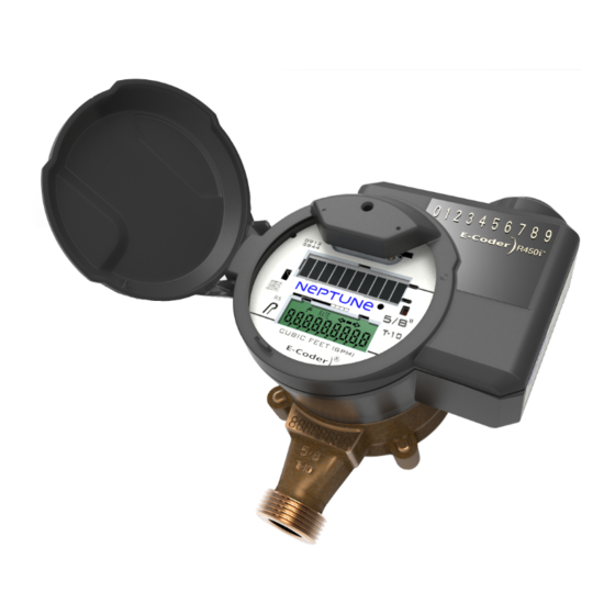
- Page 1 ® E-CODER )R450i™ Installation and Maintenance Guide...
- Page 3 ® E-CODER i™ )R450 Installation and Maintenance Guide...
- Page 4 Copyright This manual is an unpublished work and contains the trade secrets and confidential information of Neptune Technology Group Inc., which are not to be divulged to third parties and may not be reproduced or transmitted in whole or part, in any form or by any means, electronic or mechanical for any purpose, without the express written permission of Neptune Technology Group Inc.
- Page 5 RF Exposure Information This equipment complies with the FCC RF radiation requirements for uncontrolled environments. To maintain compliance with these requirements, the antenna and any radiating elements should be installed to ensure that a minimum separation distance of 20 cm is maintained from the general population.
- Page 6 ® E-CODER )R450i™ Neptune Technology Group Inc. Installation and Maintenance Guide 1600 Alabama Highway 229 Literature No. IM E-CODER)R450 09.19 Tallassee, AL 36078 Part No. 13252-001 Tel: (800) 633-8754 Fax: (334) 283-7293 Copyright © 2006 – 2019 Neptune Technology Group Inc.
-
Page 7: Table Of Contents
Contents Chapter 1: Product Description RF Protocol Error Detection Low Battery RF Emissions Chapter 2: Specifications Electrical Specifications Chapter 3: General Installation Guidelines Tools and Materials Safety and Preliminary Checks ® Chapter 4: Installing the E-CODER )R450i™ Prior to Installation Inspecting the Unit Unpacking Tools Needed... - Page 8 Contents ® Connecting the E-CODER )R450i™ Antenna ® Chapter 5: Activating and Testing the E-CODER )R450i™ Activating the LCD Using the Solar Panel RSSI Values and R450™ System Capabilities Other Sample Configuration Emails Completing the Activation ® Completing the E-CODER )R450i™...
- Page 9 Figures ® Figure 1 – E-CODER )R450i™ ® Figure 2 – E-CODER )R450i™ Dimensions Figure 3 – Pit Antenna Dimensions Figure 4 – Insert the Antenna into the Pit Lid Figure 5 – Locking Nut on Antenna Figure 6 – Secure the Locking Nut Figure 7 –...
- Page 10 Figures This page intentionally left blank. E-CODER ® )R450 i ™ Installation and Maintenance Guide...
- Page 11 Tables ® Table 1 – E-CODER )R450i™ Specifications Table 2 – Recommended Tools Table 3 – Recommended Materials Table 4 – Config Email Breakdown Table 5 – Collector RSSI Uplink ® Table 6 – E-CODER )R450i™ RSSI Downlink Table 7 – Installation Checklist Table 8 –...
- Page 12 Tables This page intentionally left blank E-CODER ® )R450 i ™ Installation and Maintenance Guide...
-
Page 13: Chapter 1: Product Description
It then transmits the data that a meter reader collects. A Neptune fixed network data collection system receives the data and stores it to download into the utility billing system for processing. - Page 14 Chapter 1: Product Description This page intentionally left blank. E-CODER ® )R450 i ™ Installation and Maintenance Guide...
-
Page 15: Chapter 2: Specifications
Chapter 2: Specifications ® This chapter defines the specifications for the E-CODER )R450i™. Electrical Specifications The following table defines the specifications for the E-CODER R450i. ® Table 1 – E-CODER )R450i™ Specifications Specification Description Environmental Conditions Operating Temperature –15º to 149ºF (–10º to +65ºC). Storage Temperature –40º... -
Page 16: Figure 2 - E-Coder ® )R450I™ Dimensions
Chapter 2: Specifications ® Figure 2 – E-CODER )R450i™ Dimensions Figure 3 – Pit Antenna Dimensions E-CODER ® )R450 i ™ Installation and Maintenance Guide... -
Page 17: Chapter 3: General Installation Guidelines
Chapter 3: General Installation Guidelines This chapter defines the tools, materials, and general installation information for the ® E-CODER )R450i™. Tools and Materials Tables 1 and 2 show the recommended tools and materials you may need to successfully install the E-CODER)R450i. Some items may not apply to your specific installation, or the list may not contain all required tools or materials. -
Page 18: Safety And Preliminary Checks
Chapter 3: General Installation Guidelines Safety and Preliminary Checks Observe the following safety and preliminary checks before and during each installation: Verify that you are at the location specified on the Site Work Order. Verify that the site is safe for you and your equipment. Notify the customer of your presence, and tell the customer that you will need access to the water meter. -
Page 19: Chapter 4: Installing The E-Coder ® )R450I
After unpacking the E-CODER)R450i, inspect it for damage. If the E-CODER)R450i appears to be damaged or proves to be defective upon installation, notify your Neptune Territory Manager or Distributor. If one or more items require reshipment, use the original cardboard box and packing material. -
Page 20: Site Selection
® Chapter 4: Installing the E-CODER )R450i™ Site Selection Installation and operation in moderate temperatures increase reliability and product life. See “Environmental Conditions” on page 3. Follow these guidelines when selecting a location for the E-CODER)R450i: Install the unit in a vertical and upright position. Clear all obstructions from the installation location. -
Page 21: Retrofit Meter Installation
® Chapter 4: Installing the E-CODER )R450i™ 6. Open the meter outlet valve slowly. 7. Open a down stream faucet and run enough water to dissipate entrained air and flush the line. While the faucet is open, verify the meter is operating correctly. 8. -
Page 22: Figure 5 - Locking Nut On Antenna
® Chapter 4: Installing the E-CODER )R450i™ 2. Thread the locking nut onto the antenna, smooth end toward lid. Figure 5 – Locking Nut on Antenna 3. Hand tighten the nut securely to the lid. Figure 6 – Secure the Locking Nut This figure shows a completed installation of the antenna. -
Page 23: Chapter 5: Activating And Testing The E-Coder ® )R450I
® Chapter 5: Activating and Testing the E-CODER )R450i™ ® This chapter defines how to read and test the E-CODER )R450i™ to identify water leaks. Activating the LCD Using the Solar Panel Complete the following steps to activate and test the E-CODER. 1. -
Page 24: Rssi Values And R450™ System Capabilities
® Chapter 5: Activating and Testing the E-CODER )R450i™ 4. When the collector receives the configuration packet, the host sends an email or Short Message Service (SMS) confirmation to allow verification of proper installation and E-CODER)R450i location. The following is an example of the email text. The subject line of the email provides a quick summary of the detailed information which is included. -
Page 25: Table 5 - Collector Rssi Uplink
® Chapter 5: Activating and Testing the E-CODER )R450i™ The E-CODER)R450i Config Email provides feedback on the RSSI values between the E-CODER)R450i and the collector following MIU activation. Depending on the RSSI values recorded, the system indicates the following values: Pass. -
Page 26: Other Sample Configuration Emails
® Chapter 5: Activating and Testing the E-CODER )R450i™ Other Sample Configuration Emails RSSI Validation Test Failed If an E-CODER)R450i fails the validation test for RSSI during the installation process, the system sends an email or SMS showing a Marginal or Failed RSSI value. In the following example email, note the Failed downlink value [–107] as well as the Marginal uplink value [–107] . -
Page 27: Completing The E-Coder ® )R450I™ Installation
® Chapter 5: Activating and Testing the E-CODER )R450i™ ® Completing the E-CODER )R450i™ Installation Before leaving the installation site, complete the following items in the checklist. Table 7 – Installation Checklist Record the E-CODER)R450i ID for each register. Verify that you have followed all requirements of this Installation and Maintenance Guide. Verify that you have recorded all required information. - Page 28 ® Chapter 5: Activating and Testing the E-CODER )R450i™ This page intentionally left blank. E-CODER ® )R450 i ™ Installation and Maintenance Guide...
-
Page 29: Chapter 6: Maintenance And Troubleshooting
Low RSSI: Tips and Techniques for New PIT MIU Installations Received Signal Strength Indicator (RSSI) is a measurement of the power present in received ® radio signal. Neptune uses this measurement during the installation process to determine if a collector is strongly receiving for an E-CODER)R450i. -
Page 30: Replacement Parts
9106-001. Lid, register 13199-003. Contact Information Within North America, Neptune Customer Support is available Monday through Friday, 7:00 A.M. to 5:00 P.M. Central Time, by telephone or email. By Phone To contact Neptune Customer Support by phone, complete the following steps. -
Page 31: By Email
A description of what occurred and what you were doing at the time. A description of any actions taken to correct the issue. By Email To contact Neptune Support by email, send your message to support@neptunetg.com. E-CODER ® )R450 i ™ Installation and Maintenance Guide... - Page 32 Chapter 6: Maintenance and Troubleshooting This page intentionally left blank. E-CODER ® )R450 i ™ Installation and Maintenance Guide...
-
Page 33: R450I™ Flags
® Appendix A: E-CODER )R450i™ Flags Description of Flags The tables in this appendix describe the volume represented by the eighth digit by meter ® size, and the flags used the by the E-CODER )R450i™. Table 9 – Eighth Digit Resolution by Meter Size Register Size Eighth Digit Resolution –... - Page 34 ® Appendix A: E-CODER )R450i™ Flags This page intentionally left blank. E-CODER ® )R450 i ™ Installation and Maintenance Guide...
-
Page 35: Glossary
Glossary antenna (pit) MIU antenna used for pit installations. antenna (whip) RF antenna that can be removed to upgrade to a through-the-lid antenna. conical-shaped gasket Cone-shaped rubber gasket on the antenna cable used to seal the cable at the top of the connector housing. - Page 36 Glossary Liquid Crystal Display (LCD) Component where the meter-reading and value-added icons are displayed. Meter Interface Unit. register read time The default time is 15 minutes for all registers. Custom time is not available. seal pin ® Small, black plastic nail used to secure the E-CODER )R900i™...
-
Page 37: Index
Index fixed network 1 functional specifications 3 activation, completing 14 antenna 9 general description 1 battery, low RF emissions 1 )R900i™ to the meter 7 ® inspect, E-CODER install, new meter 8 install, retrofit meter 9 installation config email 12 site selection, inside version 8 customer support 18 installation, checklist 15... - Page 38 Index solar panel 11 storage 7 system capabilities 12 unpack the device 7 uplink 13 weight 3 E-CODER ® )R900 i ™ Installation and Maintenance Guide...
- Page 40 ® )R450i ™ 09.19 Part No. 13252-001 © Copyright 2006-2019, IM E-CODER Neptune Technology Group Inc. Neptune is a registered trademark of Neptune Technology Group Inc.
Need help?
Do you have a question about the E-CODER) R450i and is the answer not in the manual?
Questions and answers