Table of Contents
Advertisement
Advertisement
Table of Contents

Related Manuals for Lilliput Q17


Summary of Contents for Lilliput Q17
-
Page 2: Table Of Contents
Contents Precaution..........................2 1. Main Features........................3 2. Product Description......................4 2.1 Front Panel........................4 2.2 Rear Panel........................5 3. Menu Setting........................8 3.1 Short Key........................8 3.1.1 Menu Knob.........................8 3.1.2 F1-F2 Buttons......................8 3.2 Menu Operations......................9 3.2.1 PICTURE........................9 3.2.2 MARKER........................12 3.2.3 FUNCTION.........................13 3.2.4 WAVEFORM......................15 3.2.5 AUDIO........................18 3.2.6 REMOTE........................20 3.2.7 SYSTEM........................23 4. -
Page 3: Precaution
Important Safety Instructions: Please read User Guide before using this product. Please keep User Guide for future reference. Please read the precaution to prevent possible danger and loss of property. Precaution: Please do not place the display screen towards the ground. ... -
Page 4: Main Features
1. Main Features Support standard 12G-SDI input interface (x2), 3G-SDI input interface (x2), and support Single-Link, Dual-Link and Quad-Link signals. Support HDMI 2.0/1.4 inputs and loop outputs. Support SFP optical Connector input, optical module for optional. Loop output signals support up to 3840x2160 23.98/24/25/29.97/30/50/59.94/60p and 4096x2160 23.98/24/25/29.97/30/47.95/48/50/59.94/60p. -
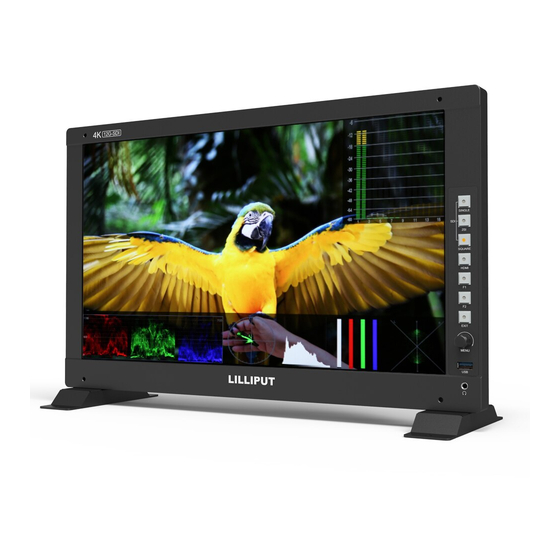
Page 5: Product Description
2. Production Description 2.1 Front Panel 1) SDI Buttons - Single Button/Lamp: SDI1/SDI2/SDI3/SDI4/SFP signal input. - 2SI Button/Lamp - Square Button/Lamp 2) HDMI Button/Lamp 3) F1/F2 Button/Lamp Assigned function by factory as follow: - [F1]: Waveform - [F2]: Color Space 4) Exit Button 5) Menu Knob 6) USB (For 3D LUT load and software update) -
Page 6: Rear Panel
2.2 Rear Panel 2.2.1 Interfaces 1) 4pin power input for V-mount/Anton Bauer mount battery plate. 2) Power Switch: “O” is power off, “II” is battery power supply, “I” is DC power supply. 3) Power IN: 4-pin XLR DC. 4) SFP Input 5) HDMI 2.0 Input 6) HDMI 2.0 Output 7) SDI Input... - Page 7 PIN Number Instruction PIN 1 PIN 2 PIN 3 PIN 4 PIN 5 PIN 6 PIN 7 PIN 8 11) RS422 Output (RJ45, 8-pin): Supporting the default and TSL V3.1 protocols to control Monitor. The instructions about the port is as above. 12) LAN (10/100) Input (RJ45): Supporting the default protocol to control Monitor.
- Page 8 Process of Installing Battery Plate: - Install the plate base before installing the battery plate. - Standard with V-mount battery plate: Referring to the following pictures for installation process and GP-L130AB type battery. - Optional Anton Bauer battery plate. Referring to the following pictures for installation process and GP-L130B type battery.
-
Page 9: Menu Setting
3. Menu Setting Before setting the functions, please make sure the device is connected correctly. 3.1 Shortcut keys 3.1.1 Menu Knob Power on the monitor, press Menu Knob to display OSD, and select options as the following sequence via rotating it: PICTURE/MARKER/FUNCTION/WAVEFORM/AUDIO/REMOTE/SYSTEM. ... -
Page 10: Menu Operations
3.2 MENU Operation 3.2.1 PICTURE SDI Mode HDMI Mode Brightness Control the degree of brightness between 0-100. Contrast Control contrast ratio between 0-100. Saturation Adjust the color intensity between 0-100. Tint Adjust tint between 0-100. Sharpness Control sharpness of the image between 0-100. - Page 11 Select the color space from among [Native], [SMPTE-C], [Rec709], [EBU]. Camera Log Use this item to choose one of the camera Log modes: - [Off]: Turn off Camera Log. - [Def. Log]: Use this item to choose one of the Camera Log modes as the following sequence: [SLog2ToLC-709], [SLog2ToLC-709TA], [SLog2ToSLog2-709], [SLog2ToCine+709], [SLog3ToLC-709], [SLog3ToLC-709TA], [SLog3ToSLog2-709], [SLog3ToCine+709].
- Page 12 Note: Gamma mode can be only activated while HDR function closed. HDR Use this item to choose one of the HDR presets: [Off], [ST 2084 300], [ST 2084 1000], [ST 2084 10000], [HLG]. Back Light Mode - [Standard]: Activate the standard mode. - [Outdoor]: Activate the outdoor mode.
-
Page 13: Marker
3.2.2 MARKER Center Marker Select [On] to display the center marker “+” and [Off] not to display it. Aspect Marker Select the aspect ratio of the marker: [Off], [16:9], [1.85:1], [2.35:1], [4:3], [3:2], [2.0X], [2.0X MAG], [Grid], [User]. ... -
Page 14: Function
Aspect Mat. When activated, it can be selected from 1-7 (Step value is 1). Thickness Adjust the thickness of all the marker lines from 1-7 (Step value is 1). User Marker H1/H2: Adjust the position of vertical markers from 1 to 1920. V1/V2: Adjust the position of horizontal markers from 1 to 1080. - Page 15 Overscan Use this item to activate or deactivate overscan. H/V Delay Select one of the H/V modes: [OFF], [H], [V], [H/V]. When H/V Delay on, the blanking portions of the input signal will be displayed horizontally and vertically. ...
-
Page 16: Waveform
Image Flip Allow the displayed image to be flipped horizontally or vertically by selecting one of flip mode from among [H], [V], [H/V]. SDI Format Select the format of SDI input signal from among [Auto], [GBRA444 10Bit], [YCbCrA444 10Bit], [YCbCrA422 12Bit], [GBR444 12Bit], [YCbCr444 12Bit]. - Page 17 Vector Use this item to activate or deactivate Vector. Transparency Adjustment of transparency can support waveform, vector, histogram, 4 bar display, audio vector, level meter. Transparency can be selected from among [off], [25%], and [50%]. - [Off] : The background of waveform is shown at black. - [25%]: The background of waveform is shown at 25% intensity.
- Page 18 False Color Use this item to activate or deactivate the false color function. When activated, [Default], [Spectrum], [ARRI], [RED] are for optional. False Color Table Use this item to activate or deactivate the false color table. The range of the false color table is between 0-100 IRE.
-
Page 19: Audio
- [Color], Display RGB separated histogram. 4 Bar Display Select whether to activate or deactivate 4 Bar Display. When activated, it displays the range of Y and RGB between minimum and maximum value. TimeCode Use this item to activate or deactivate the TimeCode. When activated, [LTC], [VITC] are for optional. Note: Time code is only available under SDI mode. - Page 20 Audio Vector Select whether to activate or deactivate audio vector. Audio phase can be monitored by the audio vector. Vector Ch In HDMI mode, select the vector channels from among [Ch1&Ch2], [Ch3&Ch4], [Ch5&Ch6], and [Ch7&Ch8]. In SDI mode, select the Vector Channels from among [Ch1&Ch2], [Ch3&Ch4], [Ch5&Ch6], [Ch7&Ch8], [Ch9&Ch10], [Ch11&Ch12], [Ch13&Ch14], and [Ch15&Ch16].
-
Page 21: Remote
3.2.6 REMOTE DHCP - [On]: The monitor will automatically get an IP address from network for remote control via various programs. - [Off]: Manually configure IP address. IP Address Manually configure IP address: xxx.xxx.xxx.xxx Note: When [DHCP] on, IP address cannot be manually set . ... - Page 22 RS ID Set the ID of RS422 communication. The valid address range is between 1-126. Note: ID must be unique in a RS422 network. Baud Rate Select one of RS422 Baud Rate: [19200], [38400], [57600]. Note: Set the same Baud Rate in PC’s monitoring software. ...
- Page 23 PIN Number Settable Values Single/2SI/SQUARE HDMI Center Marker 16:9 Marker/1.85:1 Marker/2.35:1 Marker/ 4:3 Marker/3:2 Marker/2.0X Marker/2.0X MAG Marker/ Grid SA 95%/SA 93%/SA 90%/SA 88%/SA 85%/SA 80% Pixel To Pixel Blue Only H/V Delay Peaking False Color Exposure Mute Level Meter Audio Vector Tally Red/Tally Green Power...
-
Page 24: System
3.2.7. SYSTEM Language Option: [Chinese], [English]. SFP Option: [On], [Off]. When the SFP on, SFP signal input can be selected via SDI-Single button on the front panel. Color Bar Turn on/off color bar. When the color bar on, it can be selected: [100%], [75%]. ... - Page 25 - [Full]: it can support signal input, UMD, Tally and internal temperature display. As shown in the following picture, - UMD feature in the info. windows: Support user UMD input data on screen, ASCII: 0x20~0x7e Support display a pair of tally signal and up to 16 characters that are input by TSL protocol V3.1 on the screen.
- Page 26 Fan Option: [Auto], [On], [Off]. Default: [Auto]. - [Auto]: The monitor will automatically turn on/off the fan according to the setting value of fan auto temp. Knob Customized Knob function, custom option: [Brightness], [Contrast], [Saturation], [Tint], [Sharpness], [Volume], [Peaking Level], and [Back light]. Default: [Back Light]. Please refer to 3.1.1 for Knob specific operation instructions.
-
Page 27: Product Parameters
Option: [Off], [Gamma&HDR], [Color Space], [Camera Log]. Default: [Off]. Reset Select the Reset option, press the Menu knob to automatically reset. 4. Product Parameters Panel Size 17.3" Resolution 1920×1080 Luminance of white 300 cd/m² Contrast Ratio 1200:1. Viewing Angle 170°/170°(H/V) Input Connector 12G-SDI*2, 3G-SDI*2, HDMI 2.0, GPI, RS422, LAN, USB... -
Page 28: Accessories
4. Accessories Standard: 1) 15V/4A DC Adapter 2) VESA Mount Plate Bracket 3) V-mount (or Anton Bauer Mount) 4) Base Bracket 1 pair 5) Gimbal Bracket 6) Suitcase 7) Acrylic Screen Protector 8) 8GB USB flash drive (User guide and software included) ... -
Page 29: Trouble Shooting
6. TROUBLE SHOOTING 1) Only black-and-white display: Check whether the color saturation is properly setup or not. 2) Power on but no pictures: Check whether the cables of SDI and HDMI are correctly connected or not. Please use the standard power adapter coming with the product package. -
Page 30: Appendix: 3D Lut Loading & Remoteterminal Instructions
User Log: User1. cube-User6.cube LUT Format conversion The format of LUT should be transformed if it doesn’t meet Lilliput’s requirement. It can be transformed by using LightSpace CMS or LILLIPUT LUT Tool.exe. LightSpace CMS software user demo... - Page 31 - Select File > import > *LUT - Select File > Export, Select Lilliput17(*.cube)
- Page 32 LILLIPUT software user demo - Activate LUT Tool.exe. - Click Input File, then select *LUT.
- Page 33 Click “Yes” on the pop-up prompt window (If the device doesn’t pop-up the prompt window, please check if the LUT document name or the USB flash disk version meets Lilliput’s requirement.), then press Menu button to update automatically. It will pop-up a prompt message if the...
- Page 34 Appendix 2: RemoteTerminal Instructions Remotely control the device by RemoteTerminal application. Home Screen Picture: The home screen of the application Input: Display the signal format of the connected device. For example, there is “No Signal” when no device is connected or no signal is input. ...
- Page 35 Function Port Selection: Select the specific connection port according to the device interface and click “LAN” or “RS422” to switch. When RS422 selected, it needs to further set the COM name and baud rate. For baud rate, it needs to be adapted to the baud rate of the connected device. ...
Need help?
Do you have a question about the Q17 and is the answer not in the manual?
Questions and answers