Table of Contents
Advertisement
Advertisement
Table of Contents

Related Manuals for Key-Disp KD51C-U


Summary of Contents for Key-Disp KD51C-U
-
Page 2: Table Of Contents
Contents Product Name and Model....................1 Specifications........................1 Appearance and Size....................... 1 Function Summary......................2 ◆Function Summary........................2 ◆Functional Area Distribution......................3 General Operation......................3 ◆Switching the E-bike System On/Off..................3 ◆Display Interface......................... 3 ◆Switching Push-Assist Mode On/Off..................4 ◆Switching the Lighting On/Off....................4 ◆Assist Level Selection........................ - Page 3 Throttle Push-Assist Enable/Disable..................12 Throttle Level Enable/Disable....................13 System Settings (optional).................... 13 ◆Delay Time Settings of Battery Power.................. 13 ◆Max Speed Limited........................14 ◆Push-Assist Enable/Disable....................14 ◆Slow Start Up Settings......................15 ◆Power-on Password Settings....................15 ◆Power-on Password Enable/Disable..................15 ◆Power-on Password Modify....................16 ◆Exit Settings..........................16 Recover Default Settings....................
-
Page 4: Product Name And Model
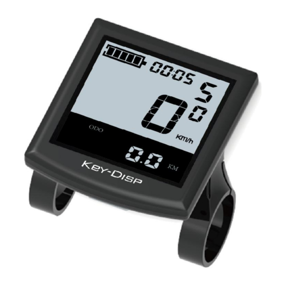
Product Name and Model Intelligent LCD display of E-bike Model: KD51C. Specifications ●Rated voltage: 24V/36V/48V ●Rated working current: 10mA ●Maximum working current: 30mA ●Off-state leakage current: <1uA ●Operating temperature: -20℃~ 60℃ ●Storage temperature: -30℃~ 70℃ Appearance and Size Product appearance and dimensional drawing (unit: mm) -
Page 5: Function Summary
Remote appearance and dimension (unit: mm) Function Summary ◆Function Summary KD51C has many functions to meet the bikers’ needs. The indicating contents are as follows: ●Smart battery indicator ●Assist-level indication ●Speed indication (incl. running speed, max. speed and average speed) ●ODO meter and trip distance ●The push-Assist function ●Trip time indication... -
Page 6: Functional Area Distribution
●Error code indication ●Motor-output indication (optional) ●Pedaling frequency indication (optional) ●The remaining range indication (optional) ●Various parameters settings (e.g., wheel size, speed-limited, battery level bar, Assist level, controller limited current, max speed, password enable, etc.) ●Recover default settings ◆Functional Area Distribution Functional Area Distribution General Operation ◆Switching the E-bike System On/Off... -
Page 7: Switching Push-Assist Mode On/Off
Display interface ◆Switching Push-Assist Mode On/Off To activate the push-Assist function, keep holding the “-” button. The E-bike’s is activated to go at a uniform speed of 6 Km/h while ‘ WALK’ is shown on the display screen. The push-Assist function is switched off as soon as you release the “-” button on the operating unit. -
Page 8: Assist Level Selection
◆Assist Level Options The level of Assist of the E-bike drive when pedaling can be adjusted via the display. The Assist level can be changed anytime, even during riding. The default Assist level ranges from level “0” to level “5”.The output power is zero on Level “0”. -
Page 9: Error Code Indication
◆USB Connection Indicator The external devices can be charged by the display by using a matching USB cable to connect the display USB port to a smart-phone or similar devices. (5V charging voltage and max 1 A charging current). USB Connection Indicator ◆Error Code Indication The components of the E-bike system are continuously and automatically monitored. -
Page 10: Backlight Contrast Settings
◆Backlight Contrast Settings ‘bL’ represents backlight settings. Level “1” is the low brightness, Level “2” is the medium brightness, and Level “3” is high brightness. The default level is “1”. To modify the backlight brightness, press the “+” button or the “-” button to choose the desired setting value. -
Page 11: Wheel Diameter Settings
◆Wheel Diameter Settings Ld represents wheel diameter settings. Optional values are 16, 18, 20, 22, 24, 26, 700C and 28. The default value is 26 inch. To change basic settings, press the “+” or the “-” button to increase or decrease until the desired value is displayed. -
Page 12: Battery Power Bar Settings
Settings, Throttle Function Settings, System Settings and Power-on Password Settings. To access Personalized Parameter Settings page, hold both the “+” and the “-” button for 2s (General Settings page) and hold both the “+” and the “-” button for 2s again. To access the corresponding setting, press the “+”... -
Page 13: Pas Ratio Settings
To change the mode of Assist-level, press the “+” or the “-” button to choose the desired mode, and then press the “i” button to confirm, and then access the PAS ratio settings page automatically. PAS Mode Option Interface PAS Ratio Settings To change the value of PAS ratio, press the "+"... -
Page 14: Power Assistant Sensor Settings(Optional)
CUR Settings Interface ◆Power Assistant Sensor Settings (optional) The Direction of PAS Settings PAS represents power assistant sensor settings. “run-F” means forward direction, while “run-b” means back direction. The default value is “run-F”. To change The Direction of Power Assistant Sensor Settings, press “+” or “-” button to select F or b. -
Page 15: Magnet Quantity Settings
The Sensitivity of PAS Settings Magnet Quantity Settings n represents magnet numbers of PAS disk. The default value is 6. To change magnet numbers of PAS disk, press “+” or “-” button to choose magnet quantity for PAS disk. To store a changed setting, hold the “i” button and then return to previous menu. PAS Magnet Disk Settings ◆Speed Sensor (optional) SPS represents speed sensor settings. -
Page 16: Throttle Level Enable/Disable
function is disabled. HL-y represents throttle Assist push function is enabled. The default value is N. To change throttle push-Assist function, press the “+” or the “-” button to select Y. To store a changed setting, press “i” button. Otherwise, to select N and then access Throttle Level Enable Settings. -
Page 17: Max Speed Limited
Delay Time of Battery Power Interface Max. Speed Limited LS represents max speed limited settings. The default value is 40Km/h. To change Max speed limited setting, press the “+” or the “-” button to set the max speed from 25Km/h~40 Km/h. To store a modified setting, press the “i”... -
Page 18: Slow Start Up Settings
Slow Start up Settings SSP represents slowly start up and the range is “1-4”, “4” is the slowest. The default value is “1”. To change slowly start up settings, press the “+” or the “-” button to select the desired value. -
Page 19: Power-On Password Modify
otherwise exit the power-on password settings interface. The default value is N. Y is power-on password enable. N is power-on password disable. Power-on Password Disable Interface ◆Power-on Password Change When the display shows P3, 0000, to set new power-on password, press the “+” or the “-”... -
Page 20: Recover Default Settings
Recover Default Settings dEF represents recover default settings. The default value is N. To access recover default settings, hold both the “-” and the “i” button for 2s. Press “+” or “-” button to choose Y or N again. N means that do not recover default settings. -
Page 21: Connection Layout
Wire connection layout Connector wire sequence Connector to controller display end connection wire end to display end Wire sequence table Wire sequence Color Function Red(VCC) Blue(K) Lock Black(GND) Green(RX) Yellow(TX) ■Some products have wire connection with water-proof connectors; users can’t see the color of wires in the harness. - Page 22 Attached list 1:Error Code Definition Error Code Definition Current Abnormality Throttle Abnormality Motor Phase Abnormality Motor Hall Signal Abnormality Brake Abnormality Communication Abnormality Attached list 2:PAS ratio default value table level PAS level Mode 0-3/1-3 — — — — — —...
Need help?
Do you have a question about the KD51C-U and is the answer not in the manual?
Questions and answers
Здравствуйте. Key-disp KD51C: нужна пошаговая инструкция средних или максимальных настроек с колесом 16 дюймов. Велосипед smartbalans hunter (yakamuro apache).Благодарю!