Table of Contents
Advertisement
Quick Links
Advertisement
Table of Contents

Related Manuals for Key-Disp KD51C


Summary of Contents for Key-Disp KD51C
-
Page 2: Table Of Contents
Content Content Product Name and Model Specifications Appearance and Size Function Summary Function Summary ◆ Functional Area Distribution ◆ General Operation Switching the E-bike System On/Off ◆ Display Interface ◆ Switching Push-assistance Mode On/Off ◆ Switching the Lighting On/Off ◆ Assistance Level Selection ◆... - Page 3 System Settings (optional) Delay Time Settings of Battery Power ◆ Button Push-Assistance Enable/Disable ◆ Push-Assistance Speed Settings ◆ Slowly Start Up Settings ◆ Power-On Password Settings ◆ Power-On Password Enable/Disable ◆ Power-On Password Modify ◆ Exit Settings ◆ Recover Default Settings Quality Assurance and Warranty Scope Connection Layout Operation Cautions...
-
Page 4: Product Name And Model
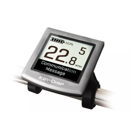
Product Name and Model Intelligent LCD display for E-bike; model: KD51C. Specifications 24V/36V/48V Power Supply ● Rated working current: 10mA ● The maximum working current: 30mA ● Off leakage current: <1uA ● The supply controller working current: 50mA ● Working temperature: -20℃~ 60℃... -
Page 5: Content
Function Summary Function Summary ◆ KD51C can provide a lot of functions to fit the users’ needs. The indicating contents are as follows: Smart battery indicator ● Assistance-level indication ● Speed indication (incl. running speed, max speed and average speed) ●... -
Page 6: Functional Area Distribution
Functional Area Distribution ◆ General Operation Switching the E-bike System On/Off ◆ Briefly press the power button to switch on the E-bike system, To hold the power button for 2 s again, the E-bike system will be switched off. When switching off the E-bike system, the leakage current is less than 1 uA. ■... -
Page 7: Switching Push-Assistance Mode On/Off
Switching Push-assistance Mode On/Off ◆ To activate the push-assistance function, hold the “-” button always. The E-bike’s drive is activated at a uniform speed of 6 Km/h. And “WALK” shows on the screen. The push-assistance function is switched off as soon as you release the “-” button on the operating unit. -
Page 8: Battery Indicator
Assistance Level “5” Battery Indicator ◆ The five battery bars represent the capacity of the battery. Each bar of the battery pack symbol is equivalent to a capacity of approx. 20%. When the battery is at low voltage, the battery frame will flash at frequency of 1 HZ to give notice that the battery needs to be recharged immediately. -
Page 9: Error Code Indication
Error Code Indication ◆ The components of the E-bike system are continuously and automatically monitored. When an error is detected, the respective error code is indicated in the text indication area. Here is the detailed message of the error code in Attached list 1. Error Code Indication ■... -
Page 10: Unit Km/Mi Conversion
Backlight Brightness Settings Interface Unit km/mi Conversion ◆ U represents unit settings, “1” is mile and “2” is kilometer. The default value is “2”. To convert a unit, press the “+” button or the “-” button to choose the desired setting item, and then press the “i”... -
Page 11: Speed-Limit Settings
Speed-limit Settings ◆ LS represents the limit speed settings. When the current speed is faster than the speed limit, the E-bike system will switch off automatically. Speed limit range is 12Km/h to 40Km/h. The default value is 25Km/h. To change basic settings, press the “+” or the “-” button to increase or decrease until the desired value is displayed. -
Page 12: Personalized Parameter Settings
Personalized Parameter Settings Personalized Parameter Settings can match a variety of requirements in use. There are 8 settings items, such as Battery Power Bar Settings, Power Assistant Level Settings, Over- current Cut Settings, Power Assistant Sensor Settings, Speed Sensor Settings, Throttle Function Settings, System Settings and Power-on Password Settings. -
Page 13: Pas Ratio Settings
PAS Mode Option Interface PAS Ratio Settings To modify the value of PAS ratio, press the "+" button or "-" button to choose the desired value, and then press the "i" button to confirm For example, the range is “45-55 percent” for level “1”, ratio value can be modified, and the default value is 50 percent. -
Page 14: Power Assistant Sensor Settings (Optional)
Power Assistant Sensor Settings (optional) ◆ The Direction of PAS Settings PAS represents power assistant sensor settings. “run-F” means forward direction, while “run-b” means backward direction. The default value is “run-F”. To change The Direction of Power Assistant Sensor Settings, press the “+” or the “-” button to select F or b. -
Page 15: Speed Sensor (Optional)
Speed Sensor (optional) ◆ SPS represents speed sensor settings. The default value is 1 To change speed sensor settings, press the “+” or the “-” button to select the quantity of magnet head on the wheel spoke (the range is from 1 to 15). To store a changed setting, hold the “i”... -
Page 16: System Settings (Optional)
System Settings (optional) Delay Time Settings of Battery Power ◆ dLY represents delay time of battery power settings. The default value is 3 s. To change delay time settings, press the “+” or the “-” button to select delay time 3 s, 6 s, 12 s. -
Page 17: Slowly Start Up Settings
Slowly Start Up Settings ◆ SSP represents a slow start up. The range is “1-4”, “4” is the slowest. The default value is “1”. To slowly start up settings, press the “+” or the “-” button to select the desired value. To return to the previous menu, hold the “i”... -
Page 18: Power-On Password Modify
Power-on Password Modify ◆ When the display shows P3, 0000, to set a new power-on password, press the “+” or the “-” button to modify the value and then press the “i” button to confirm digit one by one until the new 4-digit password is completed. To store the new power-on password, hold the “i”... -
Page 19: Quality Assurance And Warranty Scope
Quality Assurance and Warranty Scope Ⅰ Warranty 1) The warranty will be valid only for products used in normal usage and conditions. 2) The warranty is valid for 24 months after the shipment or delivery to the customer. Ⅱ Others The following items do not belong to our warranty scope. -
Page 20: Operation Cautions
Operation Cautions Be careful of safe use. Don’t attempt to release the connector when the battery is on power. ● Try to avoid hitting. ● Do not modify system parameters to avoid parameters disorder. ● Make the display repaired when an error code appears. Attached list 1:Error code definition Error Code Definition...
Need help?
Do you have a question about the KD51C and is the answer not in the manual?
Questions and answers