Key-Disp KD718 User Manual
Ebike display
Hide thumbs
Also See for KD718:
- User manual (18 pages) ,
- User manual (22 pages) ,
- User manual (22 pages)
Advertisement
Advertisement
Table of Contents

Related Manuals for Key-Disp KD718


Summary of Contents for Key-Disp KD718
-
Page 2: Product Model
Product model Intelligent TFT display for E-bike; model: KD718 Specifications 24V/36V/48V Power Supply ● Rated working current :10mA ● The maximum working current: 30mA ● Off leakage current: <1μA ● Operating temperature: -20℃~ 60℃ ● Storage temperature: -30℃~ 70℃ ●... -
Page 3: Function Summary
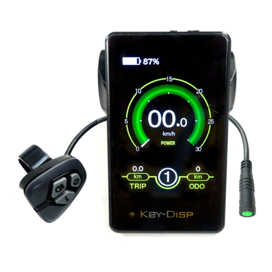
Remote appearance and dimension drawing (unit: mm) Function Summary KD718 can provide a lot of functions to fit the Users needs. The indicating contents are as follows: percentage Battery and battery indication ● Motor Power indication ● Assistance-level indication ●... -
Page 4: General Operation
General Operation ◆Switching the E-bike System On/Off Press the power button to switch on the E-bike system. To hold the power button for 2s, the E-bike system will be switched off .The E-bike system no longer uses the battery power. When switching off the E-bike system, the leakage current is less than 1 μA. - Page 5 ◆Switching Push-assistance Mode On/Off To activate the push-assistance function, hold the “-” button. After 2s, The E-bike’s drive is activated at a uniform speed of 6 Km/h while the screen displays “ ” . The push-assistance function is switched off as soon as you release the “-” button on the operating unit .The E-bike system stops the power output immediately.
- Page 6 ◆Assist Level Selection Briefly press "+" or "-" button to switch between assistance levels so as to change the motor output power, The default assistance level ranges from level “0” to level “5” , The output power is zero on Level “0”. Level “1” is the minimum power. Level “5” is the maximum power.
- Page 7 ◆Motor Power Indicator The power of the motor can be read via the interface, the lower blue rim. Motor Power Indication Interface ◆USB connection indication (optional) When the display is inserted into a USB external device, the display interface will show as below.
- Page 8 Error Code Indication ■Have the display repaired when error code appears. Otherwise, you will not be able to ride the bike normally. Please always refer to an authorized dealer. Settings Press the power button to turn on the display, To access settings menu, hold both the “+” button and the “-” button for 2s. User settings and Advanced settings are listed: Settings interface ▉All the Settings are operated on a parked e-bike.
-
Page 9: User Settings
User settings: ◆Trip Reset Trip Reset represents trip distance clearance setting. To reset trip distance, press the “+” button or the “-” button to select the Yes or No. Yes represents clearing a trip distance. No represents not clearing a trip distance. To store a changed setting, press the “i”... - Page 10 ◆Wheel Diameter Settings Wheel Diameter represents wheel diameter settings. To change basic settings, press the “+” or the “-” button to increase or decrease until the desired value is displayed. To store a changed setting, press the “i” button. The default value is 28 inch. Wheel Diameter Settings Interface ◆Speed Limit Settings Speed Limit represents the limited speed settings.
-
Page 11: Advanced Settings
◆Throttle speed limit settings: Handle S.L. represents throttle speed limit. The optional values are 6/25/30/99.9 km/h. To changed the basic settings, press the “+” or the “-” button to increase or decrease until the desired value is displayed. To store a changed setting, Press the “i” button. The default value is 06 Km/h Throttle speed limit settings * After User settings are done, press BACK to return to Settings interface. - Page 12 ◆Assist Levels settings Assist levels represents assist level mode settings, 8 modes to select:0-2, 1-2, 0-4, 1-4, 0-6, 1-6, 0-8, 1-8. The default value is 0-6. To change the mode of assist level, press the “+” or the “-” button to choose the desired mode, and then press the “i”...
- Page 13 ◆Set Voltage settings Set Voltage represents battery power bar settings. 5 voltage values must be entered one by one. For example, VOL 1 is first bar voltage value. The default value is 41.5V. To set battery power bar, press the “+” or the “-” button to increase or decrease the value.
- Page 14 Quality Assurance and Warranty Scope Ⅰ Warranty 1).The warranty will be valid only for products used in normal usage and conditions. 2).The warranty is valid for 24 months after the shipment or delivery to the customer. Ⅱ Others The following items do not belong to our warranty scope. 1).The display is demolished.
-
Page 15: Operation Cautions
Make the display repaired when error code appears. ● *This manual instruction is a universal version for DISPLAY KD718. Some versions of this display may be different from specification to specification as to the software. Please always refer to an actual version Attached list 1:Error code definition...
Need help?
Do you have a question about the KD718 and is the answer not in the manual?
Questions and answers
I forgot my password for display, how do I reset it being locked out