
Related Manuals for Universal Robots OEM Control Box


Summary of Contents for Universal Robots OEM Control Box
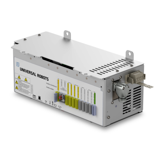
- Page 1 OEM Control Box Installation Guide Compatible robots: UR3e, UR5e, UR10e Original instructions (en)
- Page 2 Universal Robots A/S. This document is periodically reviewed and revised. Universal Robots A/S assumes no responsibility for any errors or omissions in this document. Copyright © 2019 by Universal Robots A/S. The Universal Robots logo is a registered trademark of Universal Robots A/S. OEM Control Box Installation Guide...
-
Page 3: Table Of Contents
4.3.1. Soft Start Circuit 4.4. Robot Connection 4.5. Circuit Breaker Installation 5. Mechanical Installation 5.1. Working Environment Guidelines 5.2. Mounting the OEM Control Box 5.2.1. Grounding 6. Connecting External Devices 6.1. Control Ports 6.1.1. Connecting a Mouse, Keyboard, or Monitor 6.1.2. - Page 4 7.1. Electrical Specifications 7.2. Control Unit Heat Dissipation 7.3. Dimensions 7.4. Dimensional Drawings [mm] 8. Troubleshooting 8.1. OEM Control Box AC 8.2. OEM Control Box DC 9. Certificates 9.1. Shipping Materials 9.2. Certification of Quality 9.3. Declarations According to EU directives 9.4.
-
Page 5: Introduction
1. Introduction 1. Introduction 1.1. About this Document This document describes how to install the OEM Control Box. NOTICE Universal Robots disclaims any liability, even if all guidelines in this document are followed. 1.2. What Does the Box Contain The box contains the following items:... -
Page 6: Safety
DANGER Performing installation or maintenance of a device connected to a power source can lead to electric shock. Ensure that the OEM Control Box is disconnected from the power source before performing installation or maintenance. OEM Control Box Installation Guide... - Page 7 NOTICE ESD can damage sensitive components in the OEM Control Box. Always wear an ESD wrist strap when working with the OEM Control Box electrical interfaces. CAUTION Failure to perform a risk assessment before installing and operating the OEM Control Box may result in equipment damage or personnel injury.
-
Page 8: Electrical Installation: Ac Mains
3. Electrical Installation: AC Mains 3. Electrical Installation: AC Mains This section describes how to connect the OEM Control Box to AC mains. For information on connecting the product to the DC source, see 4. Electrical Installation: DC Source on page 8. -
Page 9: How To Connect Wires To The Connector
1. Connect the following three wires to the connector: Neutral Line Ground 2. Connect the neutral, and line wires to mains. Connect the ground wire to the facility ground. 3. Plug the connector into the power source socket on the OEM Control Box. Installation Guide OEM Control Box... -
Page 10: Robot Connection
Use a double pole circuit breaker to protect the power input connector, as it can also be used as a switch. If a fuse is used, then a two-pole switch must be installed between the fuse and power input connector. The following illustration shows the circuit breaker wiring scheme. Power input Circuit breaker OEM Control Box Installation Guide... - Page 11 3. Electrical Installation: AC Mains CAUTION The installation must comply with the standard IEC 60364. Installing appropriate fuses or circuit breakers to protect the cable and system is the responsibility of the installer. Installation Guide OEM Control Box...
-
Page 12: Electrical Installation: Dc Source
4. Electrical Installation: DC Source 4. Electrical Installation: DC Source This section describes how to connect the OEM Control Box to a DC source. For information on connecting the product to the AC mains, see 3. Electrical Installation: AC Mains on page 4. -
Page 13: How To Connect Wires To The Connector
Reversing the DC source polarity causes permanent damage to the OEM Control Box. Damage caused by invalid power source connection is not covered by warranty. Ensure that the polarity is correct before powering up the Control Box. Installation Guide OEM Control Box... -
Page 14: Soft Start Circuit
4.3.1. Soft Start Circuit NOTICE When the OEM Control Box is connected to a DC source, the inrush current can reach up to 400 A for 200 μs. This may cause damage to the DC source or shut down other electronics connected to it. -
Page 15: Circuit Breaker Installation
The following illustration shows the circuit breaker wiring scheme. Power input Circuit breaker CAUTION The installation must comply with the standard IEC 60364. Installing appropriate fuses or circuit breakers to protect the cable and system is the responsibility of the installer. Installation Guide OEM Control Box... -
Page 16: Mechanical Installation
Keep the aluminum controller frame temperature within 0–65°C. 5.2. Mounting the OEM Control Box Use the four mounting brackets to mount the OEM Control Box, see the following illustration. For dimensional drawings, refer to section 7.4. Dimensional Drawings [mm] on page 19. -
Page 17: Grounding
Insufficient airflow or warm air circulation can cause the OEM Control Box to overheat and shut down. 5.2.1. Grounding The OEM Control Box casing is electrically connected to the ground pin of the power source connector. Any conductive mounting surface must also be connected to the ground. Installation Guide... -
Page 18: Connecting External Devices
6. Connecting External Devices 6. Connecting External Devices 6.1. Control Ports The bottom side of the OEM Control Box contains a bracket with ports for connecting external devices. The following illustration shows the bracket. Teach Pendant port SD card slot... -
Page 19: Teach Pendant, Remote Control, Local Control
4. In the Header, tap Installation and select Safety. 5. Under Safety, tap Hardware. 6. In the Teach Pendant drop-down menu, select Yes. If you are prompted to use a password, insert the Safety Password and tap Unlock. Installation Guide OEM Control Box... -
Page 20: Setting Up Remote On/Off Control And Emergency Stop
6.2. Setting up Remote ON/OFF Control and Emergency Stop The OEM Control Box requires a remote ON/OFF control and an emergency stop pushbutton. The following sections describe how to install them using the I/O ports. 6.2.1. Connecting the ON/OFF Control The table below shows how to connect a remote ON/OFF control. -
Page 21: Connecting Remote Emergency Stop
Install an external Emergency Stop (E-stop) if the Teach Pendant with the default Emergency Stop is not connected to the Control Box. The following illustration shows the minimum required Emergency Stop installation. NOTE For more information, refer to the robot User Manual available on the support website: https://www.universal-robots.com/support/ Installation Guide OEM Control Box... -
Page 22: Specifications
7. Specifications 7. Specifications 7.1. Electrical Specifications OEM Control Box AC Property Unit Input Voltage External Mains Fuse (@ 100-200V) External Mains Fuse (@ 200-265V) Input Frequency Stand-by Power – <1.5 Power consumption, average (UR3e) – Power consumption, average (UR5e) –... -
Page 23: Dimensional Drawings [Mm]
7. Specifications 7.4. Dimensional Drawings [mm] Installation Guide OEM Control Box... -
Page 24: Troubleshooting
8. Troubleshooting 8. Troubleshooting 8.1. OEM Control Box AC Symptom Possible Solution The Control Box does not turn Check that the power source is wired correctly (see 3.3. Power Source Wiring on page 5). The Control Box turns on for a Pressing the Power ON button for more than 5 seconds shuts few seconds then shuts down. -
Page 25: Certificates
See section 9.5. China RoHS. 2012/19/EU – Waste of Electrical and Electronic Equipment (WEEE) For information on disposal of electrical and electronic equipment waste, refer to chapter 7, Disposal and Environment in the robot user manual. Installation Guide OEM Control Box... -
Page 26: Eu Declaration Of Incorporation
3 = UR3e, 5 = UR5e, 0 = UR10e Incorporation: Universal Robots e-Series OEM robots (UR3e, UR5e, and UR10e) shall only be put into service upon being integrated into a final complete machine (robot system, cell or application), which conforms with the provisions of the Machinery Directive and other applicable Directives. -
Page 27: China Rohs
Electronic Information Products (Ministry of Information Industry Order #39) of the Peoples Republic of China otherwise encouraging the recycle and use of electronic information products. Customer shall defend, indemnify and hold Universal Robots harmless from any damage, claim or liability relating thereto.
Need help?
Do you have a question about the OEM Control Box and is the answer not in the manual?
Questions and answers