Table of Contents
Advertisement
Quick Links
Advertisement
Table of Contents

Related Manuals for Universal Robots UR-6-85-5-A


Summary of Contents for Universal Robots UR-6-85-5-A
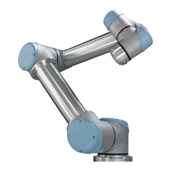
- Page 1 UR-6-85-5-A User Manual Version 1.11, January 2010...
- Page 2 UR-6-85-5-A...
-
Page 3: Table Of Contents
Contents 1 Getting started 1.1 Introduction ........1.1.1 The Robot . - Page 4 Calibrate Touch Screen ... . . 71 3.5.6 Setup Screen Network ..... . 72 UR-6-85-5-A...
- Page 5 A.1.3 Risk Assessment ......79 A.1.4 Example ....... . 79 UR-6-85-5-A...
- Page 6 Contents UR-6-85-5-A...
-
Page 7: Getting Started
No special knowledge about robots in general or Universal Robots in particular is required. The rest of this chapter is an appetizer for getting started with the robot. -
Page 8: The Robot
This freedom is given by setting a blend radius for the waypoint, which means that once the robot comes within a cer- tain distance of the waypoint, the robot can decide to deviate from the path. A blend radius of 5-10 cm usually gives good results. UR-6-85-5-A... -
Page 9: Safety Evaluation
A more detailed description of the initialization screen is found in section 3.1.2. 1.2.4 Shutting Down the Robot The power to the robot can be turned off by touching the ’OFF’ button at the initialization screen. Most users do not need to use this feature since the robot is UR-6-85-5-A... -
Page 10: Shutting Down The Controller Box
5. Plug in the mains connector of the controller box. 6. Press the Emergency Stop button on the front side of the controller box. 7. Press the power button next to the Emergency Stop button at the controller box. UR-6-85-5-A... - Page 11 29. Congratulations! You have now produced your first robot program that moves the robot between the two given positions. Remember that you have to carry out a risk assessment and improve the overall safety condi- tion before you really make the robot do some work. UR-6-85-5-A...
-
Page 12: Mounting Instructions
1.4.1 The Workspace of the Robot The workspace of the UR-6-85-5-A robot extends to 850 mm from the base joint. The workspace of the robot is shown in figure 1.2. It is important to consider the cylindrical volume directly above and directly below the robot base when a mounting place for the robot is chosen. - Page 13 Surface on which the robot is fitted. It should be flat within 0.05mm Outer diameter of robot mounting flange Cable exit 132 ±0,5 Figure 1.3: Holes for mounting the robot, scale 1:1. Use 4 M8 bolts. All measure- ments are in mm. UR-6-85-5-A...
- Page 14 1.4. Mounting Instructions Figure 1.4: The tool output flange, EN ISO 9409-1-A50. This is where the tool is mounted at the tip of the robot. All measures are in mm. UR-6-85-5-A...
-
Page 15: Mounting The Controller Box
1.1. The controller box should be connected to earth by the mains cable. If other earth connections are needed for external equipment, please use the M8 screw at the bottom right corner of the controller box, as shown below. UR-6-85-5-A... - Page 16 1.4. Mounting Instructions UR-6-85-5-A...
-
Page 17: Electrical Interface
Chapter 2 Electrical Interface 2.1 Introduction There are electrical inputs/outputs (I/Os) inside the controller box and at the robot tool flange. Some of the I/Os inside the controller box are dedicated to the robot emergency stop functionality, and some I/Os allows the robot to communicate with other machines and equipment. -
Page 18: The Emergency Stop Interface
figure 2.1. It is important to notice that any short circuit or lost connection will lead to an emergency stop, UR-6-85-5-A... -
Page 19: The Simplest Emergency Stop Configuration
This is done with the configuration shown above. This configuration is the default when the robot leaves the factory, and thereby the robot is ready to operate. However, the emergency configuration should be changed if required by the risk assessment. UR-6-85-5-A... -
Page 20: Connecting An External Emergency Stop Button
24V voltage source, and connect all emergency stop button in series, and then all the relays of the machinery. An example with two UR robots is shown below. Remember to check that all emergency stop buttons are rated for the total current consumption of all the connected emergency stop relays. UR-6-85-5-A... -
Page 21: The Pause Interface
You need a Pause connector. Open the controller box and look near the top. Locate the Pause placeholder plug. Remove the placeholder. Plug in the Pause connector. When the pause connector is in place, a pause device can be wired as shown below. UR-6-85-5-A... -
Page 22: Controller I/O
Analog input number x plus Analog input number x minus Table 2.3: Abbreviations for the I/O interface inside the controller box. To get a good understanding of the I/O interface, a simplified version of the internal circuitry is shown below. UR-6-85-5-A... -
Page 23: Digital Outputs
The digital outputs are limited by the data specified in table 2.5. Note that the digital outputs are not current limited and overriding the specified data can cause permanent damage. To illustrate clearly how to use the digital output ports, some simple examples are shown. UR-6-85-5-A... -
Page 24: Digital Inputs
floating input will always read low. The voltages at which the inputs are guaranteed to read low or high are shown with the other data in table 2.6. To make it clear how easy it is to use digital inputs, some simple examples are shown. UR-6-85-5-A... - Page 25 UR robots are communicating with each other is illustrated below. The UR robot on the left side is communicating with the robot on the right side. A typical value for the resistor shown is 10kohm. The three-terminal box is just a terminal strip. UR-6-85-5-A...
-
Page 26: Analog Outputs
Care must be taken when the wiring is done, and it must be kept in mind that disturbing signals induced into analog outputs may also be present on other analog I/O. UR-6-85-5-A... -
Page 27: Analog Inputs
If it is not possible to achieve a differential signal from the equipment used, a so- lution could look something like the setup above. Unlike the non-differential ana- log output example in subsection 2.4.3, this solution would be almost as good as the differential solutions. UR-6-85-5-A... -
Page 28: Tool I/O
Note that the tolerance of the resistor and the ohmic change due to tempera- ture must be added to the error specifications of the analog inputs. 2.5 Tool I/O At the tool end of the robot there is a small connector with eight connections. UR-6-85-5-A... -
Page 29: Digital Outputs
Table 2.11 lists the specified data. Note that the digital outputs in the tool are not current limited and overriding the specified data can cause permanent damage. To illustrate clearly how easy it is to use digital outputs, a simple example is shown. UR-6-85-5-A... -
Page 30: Digital Inputs
To illustrate clearly how easy it is to use digital outputs, a simple example is shown. Using Digital Inputs The above example shows how to connect a simple button or switch. A bad quality switch might trigger the input twice due to a long mechanical stabilizing UR-6-85-5-A... -
Page 31: Analog Inputs
I/O tab (see section 3.3.2). Remember to check that a sensor with voltage output can drive the internal resistance of the tool, or the measurement might be invalid. UR-6-85-5-A... - Page 32 2.5. Tool I/O Using Analog Inputs, Differential Using sensors with differential outputs is also straightforward. Simply connect the negative output part to GND (0V) with a terminal strip and it will work in the same way as a non-differential sensor. UR-6-85-5-A...
-
Page 33: Polyscope Software
Chapter 3 PolyScope Software... -
Page 34: Introduction
Whenever a text or number input is needed, an on- screen keypad or keyboard is provided. The on-screen keypad, keyboard and expression editor can be reached using the buttons shown above. The various screens of PolyScope are described in the following sections. UR-6-85-5-A... -
Page 35: Welcome Screen
Program Robot: Change a program, or create a new program. Setup: Set passwords, upgrade software via the Internet, request support, calibrate the touch screen, etc. Shut Down Robot: Shuts down the Controller PC and powers off the robot. 3.1.2 Initialization Screen UR-6-85-5-A... - Page 36 In the case where a joint is in a position where there is a major risk that uncon- trolled motion would cause damage to the robot or its surroundings. The operator can choose to home the robot manually for each joint. Each joint needs to move until the status LED changes to green (see section 3.1.2. UR-6-85-5-A...
-
Page 37: On-Screen Editors
Simple number typing and editing facilities. In many cases, the unit of the typed value is displayed next to the number. 3.2.2 On-screen Keyboard Simple text typing and editing facilities. The Shift key can be used to get some additional special characters. UR-6-85-5-A... -
Page 38: On-Screen Expression Editor
An expression can look like this: digital_in[1]=True and analog_in[0]<0.5 3.3 Robot Control 3.3.1 Move Tab On this screen you can always move (jog) the robot directly, either by translat- ing/rotating the robot tool, or by moving robot joints individually. UR-6-85-5-A... - Page 39 If the gravity setting (see 3.3.4) in the Setup tab is wrong, or the robot carries a heavy load, the robot might start moving (falling) when the ’Backdrive’ button is pressed. In that case, just release the ’Backdrive’ button again. UR-6-85-5-A...
-
Page 40: I/O Tab
Analog Range Settings The analog output can be set to either current [4- 20mA] or voltage [0-10V] output. The analog input ranges adjusted to be from [-10-10V] to [0-5V]. The settings will be remembered for eventual later restarts of the robot controller when a program is saved. UR-6-85-5-A... -
Page 41: Automove Tab
Release the button to stop the motion at any time! Manual Pushing the Manual button will take you to the MoveTab where the robot can be moved manually. This is only needed if the movement in the animation is not preferable. UR-6-85-5-A... -
Page 42: Setup Mounting
(180 ), wall (90 ), floor (0 ). The Tilt buttons can be used to set an arbitrary an- gle. The buttons on the lower part of the screen are used to rotate the mounting of the robot to match the actual mounting. UR-6-85-5-A... -
Page 43: Setup Tcp Position
TCP . This is relevant when the shape or size of the tools has been changed. Change Graphics redraws the graphics of the program to fit the new TCP . This is relevant when the TCP has been changed without any physical changes to the tool. UR-6-85-5-A... -
Page 44: Log Tab
The user can descend to a sub-directory, but he cannot get any higher than the programs folder. Therefore, all programs should be placed in the programs folder and/or sub folders under the programs folder. UR-6-85-5-A... - Page 45 field. This will cause an on-screen keyboard to pop up where the user can enter the file name directly on the screen. Open button Clicking on the Open button, will open the currently selected file and return to the previous screen. UR-6-85-5-A...
-
Page 46: Run Tab
This tab provides a very simple way of operating the robot, with as few but- tons and options as possible. This can be useful combined with password pro- tecting the programming part of PolyScope (see section 3.5.4), to make the robot into a tool that can run exclusively pre-written programs. 3.4 Programming UR-6-85-5-A... -
Page 47: Program New Program
The current command is selected by clicking the command list, or by using the Previous and Next buttons on the UR-6-85-5-A... -
Page 48: Program Command Tab,
Command Tab, <Empty> Program commands need to be inserted here. Press the ‘Structure’ button to go to the structure tab, where the various selectable program lines can be found. A program cannot run before all lines are specified and defined. UR-6-85-5-A... -
Page 49: Program Command Tab, Move
The settings of a Move command apply to the path from the robot’s current position to the first waypoint under the command, and from there to each of the following waypoints. The Move command settings do not apply to the path going from the last waypoint under that Move command. UR-6-85-5-A... -
Page 50: Program Command Tab, Fixed Waypoint
If a waypoint is a stop point with an I/O command as the next command, the I/O command is executed when the robot stops at the waypoint. However, if the waypoint has a blend radius, the following I/O command is executed when the robot enters the blend. UR-6-85-5-A... -
Page 51: Program Command Tab, Relative Waypoint
This is somewhat counter-intuitive, but is necessary to allow the robot to select the right blend path. 3.4.6 Program Command Tab, Relative Waypoint A waypoint with the position given relative to the robot’s previous position, such as “two centimeters to the left”. The relative position is defined as the UR-6-85-5-A... -
Page 52: Program Command Tab, Variable Waypoint
The first three are x,y,z and the last three are the orientation given as an axis-angle given by the vector rx,ry,rz. The length of the axis is the angle to be rotated in radians, and the vector itself gives the axis about which to rotate. UR-6-85-5-A... -
Page 53: Program Command Tab, Wait
Adjusting the weight can be neccesary to prevent the robot from security stopping unexpectedly, when the weight at the tool is different to that which is excpected. UR-6-85-5-A... -
Page 54: Program Command Tab, Popup
“OK” button under the popup before continuing the program. If the “Halt program execution” item is selected, the robot program halts at this popup. 3.4.11 Program Command Tab, Halt The program execution stops at this point. UR-6-85-5-A... -
Page 55: Program Command Tab, Comment
Command Tab, Folder A folder is used to organize and label specific parts of a program, to clean up the program tree, and to make the program easier to read and navigate. A folder does not in itself do anything. UR-6-85-5-A... -
Page 56: Program Command Tab, Loop
When looping using an expression as end condition, PolyScope provides an option for continuously evaluating that expression, so that the “loop” can be interrupted anytime during its execution, rather that just after each iteration. 3.4.15 Program Command Tab, SubProgram UR-6-85-5-A... -
Page 57: Program Command Tab, Assignment
3.4.16 Program Command Tab, Assignment Assigns values to variables. An assignment puts the computed value of the right hand side into the variable on the left hand side. This can be useful in UR-6-85-5-A... -
Page 58: Program Command Tab, If
The open Check Expression Continuously allow the conditions of the If and ElseIf statements to be evaluated while the contained lines are ex- ecuted. If a expression evaluates to False while inside the body of the If-part, the following ElseIf or Else statement will be reached. UR-6-85-5-A... -
Page 59: Program Command Tab, Script
100ms and then set it back to low again. This can make the main program code a lot simpler in the case on an external machine triggering on a rising flank rather than a high input level. UR-6-85-5-A... -
Page 60: Program Command Tab, Thread
The pattern command corresponds to one position at each execu- tion. A pattern can be given as one of four types. The first three, “Line”, “Square” or “Box” can be used for positions in a regular pattern. The regular patterns are UR-6-85-5-A... - Page 61 Each vector is divided by the interval count numbers. A specific position in the pattern is calculated by simply adding the interval vectors proportionally. UR-6-85-5-A...
-
Page 62: Program Command Tab, Pallet
A pallet operation can perform a sequence of motions in a set of places given as a pattern, as described in section 3.4.21. At each of the positions in the pattern, the sequence of motions will be run relative to the pattern position. UR-6-85-5-A... -
Page 63: Program Command Tab, Stack
On top of this, one must define the condition for when the next stack position is reached, and a special program sequence that will be performed at each of the stack positions. Also speed and accelerations need to be given for the movement involved in the stack operation. UR-6-85-5-A... - Page 64 Destacking When destacking, the robot moves from the starting position in the given direc- tion to search for the next item. When found, the robot remembers the position UR-6-85-5-A...
- Page 65 “AfterEnd” The optional AfterEnd sequence is run when the operation is finished. This can be used to signal conveyor motion to start, preparing for the next stack. A direction does not consider the orientations of the points. UR-6-85-5-A...
- Page 66 3.4. Programming Pick/Place Sequence Like for the Pallet operation (3.4.22), a special program sequence is performed at each stack position. UR-6-85-5-A...
-
Page 67: Program Graphics Tab
The motion segments shown depends on the selected program node. If a Move node is selected, the displayed path is the motion defined by that move. If a Waypoint node is selected, the display shows the following 10 steps of movement. UR-6-85-5-A... -
Page 68: Program Structure Tab
Not all commands fit at all places in a program. Waypoints must be under a Move command (not necessarily directly under). ElseIf and Else commands are required to be after an If. In general, moving ElseIf commands around can be messy. Variables must be assigned values before being used. UR-6-85-5-A... -
Page 69: Setup
3.5.4. Calibrate Screen Calibrates the “touch” of the touch screen, see sec- tion 3.5.5. Setup Network Opens the interface for setting up the Ethernet network for the robot, see section 3.5.6. Back Returns to the Welcome Screen. UR-6-85-5-A... -
Page 70: Setup Screen Initialize
The Auto button drives all joints until they are OK. The joints change drive direction when the button is released and pressed again. 3.5.3 Setup Screen Update Provided the robot is attached to the Internet, new software can be down- loaded. UR-6-85-5-A... -
Page 71: Setup Screen Password
3.5.5 Setup Screen Calibrate Touch Screen Calibrating the touch screen. Follow the on-screen instructions to calibrate the touch screen. Preferably use a pointed non-metallic object, such as a closed pen. Patience and care help achieve a better result. UR-6-85-5-A... -
Page 72: Setup Screen Network
3.5. Setup 3.5.6 Setup Screen Network Panel for setting up the Ethernet network. An Ethernet connection is not neces- sary for the basic robot functions, and is disabled by default. UR-6-85-5-A... -
Page 73: Warranties And Declarations
Warranty default becoming evident. Ownership of de- vices or components replaced by and returned to Universal Robots shall vest in Universal Robots. Any other claims resulting out of or in connection with the device shall be excluded from this Warranty. Nothing in this Warranty shall at- tempt to limit or exclude a Customer’s Statutory Rights, nor the manufacturer’s... -
Page 74: Declaration Of Incorporation
According to the machinery directive 2006/42/EC, the robot is considered a partly completed machine. The following subsections corresponds to and are in accordance with annex II of this directive. 4.2.1 Product manufacturer Name Universal Robots ApS Address Svendborgvej 102 5260 Odense S Denmark... -
Page 75: National Authority Contact Information
Also note that the WEEE directive 2002/96/EC is listed because of the crossed- out wheeled bin symbol on the robot and the control box. Universal Robots reg- isters all robot sales within Denmark to the national WEEE register of Denmark. -
Page 76: Important Notice
The robot may not be put into service until the machinery into which it is to be incorporated has been declared to be in conformity with the provisions of the Machinery Directive 2006/42/EC and with national implementing legislation. 4.2.7 Place and Date of the Declaration Place Universal Robots ApS Svendborgvej 102 5260 Odense S Denmark Date 29. -
Page 77: A Safety Assessment
Appendix A Safety Assessment... -
Page 78: Ce Certification Of The Robot Installation
This new machine also has to be certified. A.1.1 Safety Requirements The UR-6-85-5-A is a small and light industrial robot, with advanced motor con- trol and surveillance of the robot’s functions. Universal Robots has put much effort into making the robot as safe as possible. In Europe, the standard ISO 10218-1:2006 describes the requirements for a robot to operate without safety shielding. -
Page 79: Risk Assessment
first aid. Therefore, the lowest line of the risk assessment table is used, resulting in risk class C. The risk can be further reduced, for instance by blocking the passage of people during programming and testing of the robot. UR-6-85-5-A... - Page 80 UR-6-85-5-A...
Need help?
Do you have a question about the UR-6-85-5-A and is the answer not in the manual?
Questions and answers