Table of Contents
Advertisement
Quick Links
Advertisement
Table of Contents
Troubleshooting

Related Manuals for ZOLL IVTM


Summary of Contents for ZOLL IVTM
- Page 1 IVTM Intravascular Temperature Management O P E R A T I O N M A N U A L EMERGO EUROPE Prinsessegracht 20 EC REP 2514 AP The Hague The Netherlands Caution: Federal law restricts this device to sale by or on the order of a physician.
- Page 3 ©2019 ZOLL Circulation, Inc. All rights reserved. Thermogard XP, Cool Line, Icy, Quattro, Solex 7, and IVTM are trademarks or registered trademarks of ZOLL Medical Corporation and/or ZOLL Circulation, Inc. All trademarks are the property of their respective owners. Patent: www.zoll.com/patents ZOLL Circulation, Inc.
- Page 4 This page intentionally left blank.
-
Page 5: Table Of Contents
Table of Contents 1. Safety Information..........................1 Overview ..............................1 Warnings, Cautions, and Notes ......................1 Definitions of Symbols and Labels Used on the Product and in the Manual ..........1 General Safety Precautions ........................2 Guidance and Manufacturer’s Declaration– Electromagnetic Emissions ........................ - Page 6 Setup .............................. 25 Standby............................27 Run - Treatment Modes ........................27 User Interface ............................28 Display Screen ..........................28 Changing Target Temperature......................30 Changing Treatment Mode ......................30 Console Menus ............................ 33 Hi/Lo Patient Temperature Alarms ....................34 Bath Pre-set............................. 35 Time and Date..........................
- Page 7 Clean Console and Condensate Pan ....................95 Drain Coolant..........................96 8. Warranty and Service ........................99 Warranty .............................. 99 Technical Support and Resources......................99 Obtaining Service from ZOLL ........................ 99 Packing and Shipping Instructions......................99 Disposal of the Console ........................100 9. Specification ............................. 101...
- Page 8 Specifications ............................. 101...
-
Page 9: Safety Information
1. Safety Information Overview Safety is of primary concern to ZOLL Circulation, Inc. This chapter provides information on safely using the Thermogard XP system. You must read and understand the information in this chapter before operating the system. Always follow the warnings, cautions, and notes throughout this document. -
Page 10: General Safety Precautions
Audible and visual alarms generated by the console require the authorized individual to remain in close proximity to the patient throughout the procedure. • Always verify the function of the console prior to insertion of an IVTM catheter. In the event of a malfunc- tion, have other means of cooling available. •... -
Page 11: Guidance And Manufacturer's Declaration-Electromagnetic Emissions
WARNING. Electric shock risk during cardiac defibrillator discharge. The console’s protection against the effect of the discharge of a cardiac defibrillator is partially in the patient temperature probe. To prevent poten- tial hazards to the patient or operator, the console must be used in conjunction with the approved patient temperature probes listed in Specifications section of this manual. - Page 12 IEC 60601 Test Electromagnetic environment -- Immunity Test Compliance Level Level guidance Voltage Dips > Voltage Dips > 95% reduction, 95% reduction, 0.5 period At 0°, 0.5 period At 0°, 45°, 90°, 135°, 45°, 90°, 135°, Mains power quality should be that of a Voltage dips, short 180°, 225°, 270°...
- Page 13 IEC 60601 Test Electromagnetic environment Immunity Test Compliance Level Level guidance Where P is the maximum power rating of the transmitter in watts (W) according to the transmitter manufacturer and d is the recommended separation distance in meters (m). Field strengths from fixed RF transmitters, as determined by electromagnetic site 3V/m Radiated RF...
- Page 14 Separation distance according to frequency of transmitter (in meters) Radiated maximum 150 kHz to 80 MHz 150 kHz to 80 MHz 80 MHz to 800 MHz to output power of inside ISM bands inside ISM bands 800 MHz 2.7 GHz the equipment (in Watts) 0.01...
-
Page 15: Transportation, Shipping And Storage Conditions
Test Maximum Immunity Distance Band Frequency Power Test Level Service Modulation (MHz) (MHz) (V/m) 1720 GSM 1800; 1845 CDMA 1900; GSM 1900; 1 700 – Pulse modulation DECT; 1 990 217 Hz 1970 LTE Band 1, 4, 25; UMTS Bluetooth, WLAN, 2 400 –... -
Page 16: Ignition Of Flammable Anesthetic Mixtures
WARNING. Never clinically use a resistor in place of the T1 temperature probe. ZOLL supplies fixed value resistors and variable resistor test boxes (e.g the TP-400 FOGG Box) for testing, training and demonstra- tion purposes. -
Page 17: Priming The Saline Circuit
Periodically check the Start-Up Kit for significant air bubbles and replace the kit if necessary. WARNING. Never clinically circumvent the air trap alarm. ZOLL supplies air trap “dummies” for testing, training and demonstration purposes. These are fluid filled air trap assemblies that are separate from a stan- dard Start-Up Kit assembly. -
Page 18: Interference
• Inspect, and tighten if necessary, each Luer fitting (do not use instruments to tighten the fittings). 5. Inspect the tubing that returns to the pump from the patient. 6. Examine the saline bag to ensure that it has not been accidentally compromised (for example, the spike may have damaged the bag wall). -
Page 19: Introduction
(hourly) when the system is operating. It is possible for malfunctions or misuse of the sys- tem to result in patient injury or death. The ZOLL Intravascular Temperature Management (IVTM™) System is comprised of an external heat exchange console (Thermogard XP® console) and an IVTM™ endovascular heat-exchange catheter connected via a ster- ile heat exchanger and tubing circuit (Start-Up Kit). -
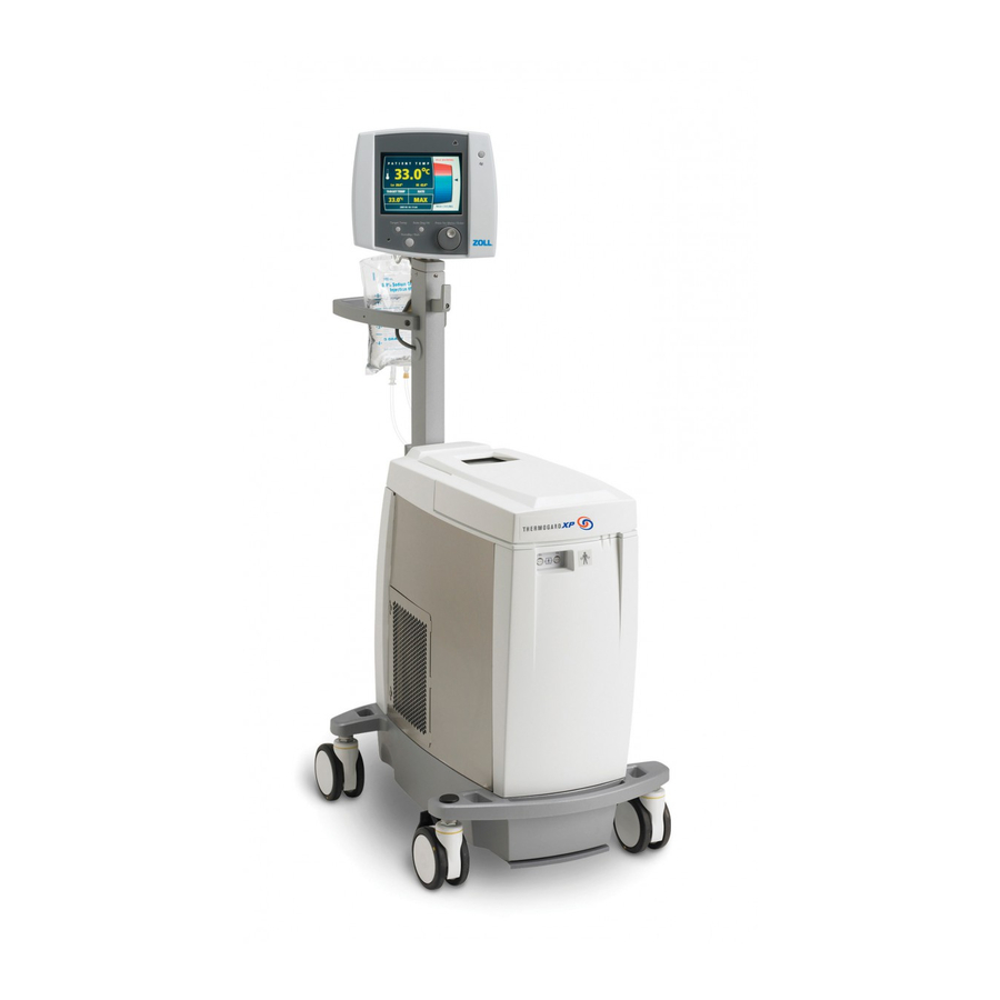
Page 20: Console Components
Patient temperature feedback is used to control the console. The patient’s temperature is measured by an indwelling YSI 400 thermistor temperature sensor. In response to the patient’s measured temperature, the con- sole employs both cooling and heating. Cooling occurs when the patient’s temperature is above the set point target temperature. - Page 21 1. Display Screen 2. Alarm Indicator LED 3. Mute Button 4. Power On Indicator LED 5. Target Temp Button 6. Standby / Run Button 7. Rate Deg / Hr Button 8. Press for Menu / Enter Knob Figure 2.2. Controls and Display Screen Power Indicators An indicator lamp on the control panel is illuminated when power is switched on.
-
Page 22: Recirculating Chiller
Mute Button Press the Mute button to silence the audible alarm tone for two minutes (120 seconds). If the alarm condition has not been cleared during this two-minute period, the audible alarm will sound again. Press for Menu/Enter Knob The “Press for Menu/Enter” knob is a dual-function control knob and pushbutton. Press the knob to display a menu screen or to indicate the completion of a selection. - Page 23 The peristaltic pump has sufficient torque to severely damage a finger. If a tubing leak or failure occurs in the pump raceway, the saline solution will cause corrosion in the moving parts of the rotor. Contact your ZOLL service representative.
-
Page 24: Start-Up Kit
Figure 2.5. Pump Prime Switch The prime switch is located on the right side of the pump. The switch is used to operate the pump to prime the tubing with sterile saline solution from the saline source. When the switch is held down, the pump runs; when the switch is released, the pump stops. - Page 25 Figure 2.7. Start-Up Kit Data Memory The console is capable of continuously recording patient temperature and system activity for up to 21 days. This stored data can be downloaded to an attached computer over a serial interface using optional software furnished by ZOLL.
-
Page 26: Saline Circuit Diagram
Saline Circuit Diagram A flow diagram is printed on the inside of the top cover. Use this diagram to ensure that the Start-Up Kit has been installed correctly. Figure 2.8. Flow Diagram... -
Page 27: Indications For Use - Usa
• The Thermogard XP These systems can be used with any of the IVTM Catheters. The indications for use are specific to the catheter. Please refer to the Indications for Use statement in the catheter specific Instructions for Use. Indications for Use – Cool Line Catheters ®... - Page 28 This page intentionally left blank.
-
Page 29: Receiving, Inspection, And Assembly
Overview This chapter provides information on how to receive, unpack, and assemble the console. If your console was delivered and set up by a ZOLL representative, you may skip this chapter and turn to Chapter 4. Inspection for Damage Each console is carefully inspected before it is shipped. When the carrier delivers your console, ensure that the shipping containers are not damaged. -
Page 30: Assembly
Figure 3.1. Console Unpacked and Ready for Assembly Assembly To assemble the unpacked console, follow these steps in the indicated order. Hook 1. Attach the gray hook to the front of the mast using the short bolt provided. Use a 7/64-inch Allen wrench to tighten the bolt securely (Figure 3.2). - Page 31 Handle 2. Attach the handle to the mast using the long bolt and the short screw provided. Use a 3/16-inch Allen wrench to tighten the bolt securely. Use a 5/32-inch Allen wrench to tighten the screw (see Figure 3.3). Do not lift the console by the handle. Figure 3.3.
- Page 32 Figure 3.5. Plug the Control Cable Into the Socket Power Cord 7. Plug the female end of the power cord into the recessed power inlet connector. Wrap the power cord around the two cord hooks on the rear of the console. Condensate Pan 8.
-
Page 33: Operation
4. Operation Overview This chapter explains how to start treatment and change target temperature and rate settings during treat- ment. It provides instructions on the proper way to end treatment, including how to download patient tem- perature trend data to a laptop computer and how to remove used components and dispose of them safely. Subsections at the end of this chapter provide detailed procedures for recovering from improper shutdowns, including special procedures for downloading patient temperature trend data. - Page 34 During these tests, the peristaltic pump is stopped (to remove the patient’s heat load from the equation). The tests that are conducted depend upon the state of the console at the time of the test. The test(s) done is (are) as follows: Coolant Temperature Heating Test Cooling Test...
-
Page 35: Standby
Standby Figure 4.2. Operating Display - Standby In Standby you can interact with the full user interface of the console. You can select the target temperature, the rate and the treatment mode. Patient temperature alarms are active in Standby if the primary patient temperature probe (T1) is connected. The coolant bath temperature graph is active in Standby. -
Page 36: User Interface
Fever (FVR) In this treatment option, the console will start cooling the patient once the patient temperature is above the target temperature. It does this by keeping the bath at its coldest permissible temperature and then operating the peristaltic pump whenever the patient’s temperature moves above the target temperature. WARNING. - Page 37 Figure 4.3. Operating Screen The upper left hand of the screen displays: • The patient temperature • The “Lo” and “Hi” patient temperature alarm values. The lower left hand of the screen displays: • The programmed target temperature • The programmed treatment mode/Controlled Rate value The right hand side of the screen is used either: •...
-
Page 38: Changing Target Temperature
Changing Target Temperature 1. Press the Target Temp button once. 2. If you are in Run, you will be taken to Standby. The target temperature value may only be changed in Standby. Figure 4.5. Change target temperature in Run 3. To change the target temperature, turn the knob until the desired temperature is displayed. You may choose a temperature from 31ºC to 38ºC (87.8ºF to 100.4ºF). - Page 39 Figure 4.6. Change Rate/Temperature in Run 2. Turn the knob until the desired Treatment Mode selection is displayed. When the correct selection is displayed, press the knob once to enter the selection. Figure 4.7. Select Mode 3. If you select Controlled Rate, a second menu screen will be presented. To change the rate, turn the knob until the desired selection is displayed.
- Page 40 Figure 4.8. Select Controlled Rate 4. If you have selected Fever mode, you will be asked to confirm your selection with the reminder that Fever mode only cools and does not warm per Figure 4.9. Figure 4.9. Fever Mode Confirmation message 5.
-
Page 41: Console Menus
Console Menus Main Menu The main menu is displayed in Figure 4.4. To access the main menu, press the knob from the operating display. Some settings are accessible only in Standby mode. Available options are: Takes you to a display of the patient temperature data log. See “Temperature View Graphs Trend Data”... -
Page 42: Hi/Lo Patient Temperature Alarms
Hi/Lo Alarms Allows you to modify the low (Lo) and high (Hi) patient temperature alarms. Time and Date Allows you to modify the console time and date. Allows you to toggle between displaying temperatures in degrees Celsius or °C / °F degrees Fahrenheit. -
Page 43: Bath Pre-Set
Nature of the Alarm Figure 4.11. “Hi” Patient Temperature Alarm The alarms are both visual and audible. The alarms will not clear until the patient’s temperature no longer trig- gers the alarm state. The audible alarm may be temporarily muted for 2 minutes by pressing the Mute button. The alarm will con- tinue after that time unless it has cleared. -
Page 44: Time And Date
Figure 4.12. Bath Pre-Set Menu The console bath is cooled to its lowest permitted temperature and maintained Pre-Cool at that temperature. The console bath is heated to its highest possible temperature and maintained at Pre-Warm that temperature. The Bath Pre-set is not activated or is canceled. If canceled, the bath is main- None tained at the temperature that was measured at the time of cancellation. -
Page 45: ºc/ºf (Temperature Notation)
The time is divided into two fields: hours (designated “HH”) and minutes (“MM”). The console uses only 24-hour time notation (e.g., 3:00 p.m. is 15:00). The date is divided into three fields: year (designated “YYYY”) - month (designated “MM”) - day (designated “DD”). -
Page 46: Language
Language This menu displays the current setting for the language used for displayed text. The currently selected setting is highlighted. Figure 4.15. Language Settings To keep the current selection, press the knob once. The current setting will not be changed and the settings menu will be displayed. -
Page 47: T1/T2 Behavior
Figure 4.16. Standby Timer Menu If the console has been left in Standby for more than the specified time, an alarm will sound to remind that the console remains in Standby. Pressing the knob will reset the timer. The Standby Timer function will continue until either: •... -
Page 48: First Use Warning - No T2 Probe
patient’s core temperature. As a result, the console may inappropriately warm the patient. Failure to use a sec- ond temperature probe may result in patient injury. First Use Warning – No T2 Probe For each time the console is powered on: 1. -
Page 49: Accidental Disconnection T1/T2 Probe
Accidental Disconnection T1/T2 Probe Disconnection of the T1 probe during Run results in an alarm. Press the knob to silence the alarm. The console moves to Standby. Treatment cannot continue until the T1 probe has been replaced. Note that the patient temperature is displayed as “---“and the yellow warning banner covers the bath temperature display. -
Page 50: Alarms
T1 Temperature probe is functional. Note. In the event of an alert: Investigate and rectify the cause - refer to: Alarms and Corrective Actions on page 85 and Troubleshooting on page 89. If the alert persists, call ZOLL for service. Alarms An alarm is more serious in nature than an alert and relates to issues that will typically require a service call. -
Page 51: Your First Case
During an alarm, the patient temperature display and the patient temperature alarms are not active. Note. In the event of an alarm: Investigate and troubleshoot the cause - refer to: Alarms and Corrective Actions on page 85 and Troubleshooting on page 89. If the alarm persists, call ZOLL for service. Your First Case... -
Page 52: Preparing The Console For Treatment
Preparing the Console for Treatment To prepare the console for treatment, follow these steps in the indicated order. 1. Roll the console to a convenient position near the patient’s bedside. Plug the power cord into a hospital- grade receptacle. 2. Lock the right front caster by stepping down on the tab above the wheel. 3. - Page 53 Figure 4.23. System Pre-Cool? 7. To start cooling or warming the coldwell immediately, choose the desired option and press the “Press for Menu/Enter” knob (the “knob”) once to enter the selection. If you do not wish to begin cooling or warming the coldwell now, choose “None”...
- Page 54 Figure 4.25. Patient Data Message. 11. Choose “Delete”. You will be asked to confirm your choice to delete the data file. Choose “Yes”. A brief confirmation message will appear and then automatically close. See below. Figure 4.26. Delete Previous Patient Data 12.
- Page 55 Figure 4.27. Select Target Temp Message 13. Turn the knob until the target patient temperature is displayed. When the desired value is displayed, press the knob once to enter the selection. 14. The System Set Up screen displays the message “Select Treatment Mode”. Note that you have three choices: “Max Power”, “Controlled Rate”...
- Page 56 Figure 4.29. Select Rate Screen 17. If the console has not yet finished its self tests, the Self-Test screen is displayed. Note. NOTE: The Software Version shown in Figure 4.31 is for reference only; the current product may use a different Software Version. Figure 4.30.
-
Page 57: Installing The Start-Up Kit
Figure 4.31. Check the Following Screen There is no Start-Up Kit installed or there is a large amount of air in the air trap Air Trap chamber. Roller Pump Lid The clear plastic roller pump lid is not closed properly. The Prime Switch is being depressed (as when you use it to prime the console) or Check Prime Switch has been jammed in the On position. - Page 58 Figure 4.32. 500ml Saline Bag on Hook The Top Cover 2. Open the top cover of the console. Open the transparent top cover of the roller pump. Figure 4.33. Covers Open 3. A tubing circuit diagram is printed on the inside of the console top cover. Refer to this diagram when installing the Start-Up Kit.
- Page 59 Figure 4.34. Coolant Well Cap 5. Check the level of the coolant. The liquid level should be between the two indicator lines on the wall of the coolant well. If the level is below the bottom indicator line, add a 1:1 mixture of distilled water and propylene glycol until the liquid is at the top indicator line.
- Page 60 Figure 4.36. Start-Up Kit 7. Insert the heat exchange coil into the coolant well. Figure 4.37. Installing the Heat Exchange Coil 8. Temporarily slide the air trap into the holder.
- Page 61 Figure 4.38. Air Trap Placed In Holder The Peristaltic Pump WARNING. Finger injuries. Be careful when inserting the pump tubing that you do not catch your fingers with the roller. When the console is operating, do not attempt to circumvent the safety interlocks on the peristaltic pump lid. Do not place fingers or for- eign objects into the pump raceway when the pump is turning.
- Page 62 11. Place the flanged connector of the pump tubing into the slot on the right side of the pump head. Place flanged connector into socket on right hand side of pump raceway. Figure 4.40. Flanged Connector Fits Into Recess 12. Load the pump tubing around the rollers and into the channel of the pump head. You must turn the handle counterclockwise as you feed the tubing into the channel.
- Page 63 Figure 4.42. Replace the Cap on the Coolant Well Spike the Saline Bag 15. Using aseptic technique, connect the priming line to the sterile saline container. The priming line is equipped with a “spike” connector. Hang the saline container on the hook provided. Figure 4.43.
- Page 64 Figure 4.44. Hold the Air Trap Upside Down 17. Prime the air trap and the tubing circuit by pressing and holding the Prime switch. The roller pump will slowly start and take about 20 seconds to come up to operating speed. Observe the movement of saline until it fills the air trap and the entire length of the tubing.
- Page 65 Figure 4.46. Route the Tubing Out of the Console 21. Lift the saline container off the hook and slip the insulating jacket around the container. Carefully close the hook-and-loop fasteners at the top and bottom of the jacket. Rehang the container on the hook. 22.
- Page 66 “T2” on the front of the console. If you are not using a secondary temperature probe, the patient MUST be monitored by a separate hospital patient temperature monitor. 5. Place the ZOLL catheter in the patient now. Refer to the Instructions for Use for information about the catheter.
- Page 67 Figure 4.50. Connect the Tubing to the Catheter 8. Connect the male tubing connector to the female connector on the catheter. Note that the return line is equipped with an inline flow-indicator. 9. Safely route the tubing so that it is not kinked or obstructed and cannot be easily dislodged by a patient’s movement.
-
Page 68: Setup - Variations
Do not keep replenishing saline that is being rapidly depleted–a problem exists that must be immediately rem- edied. For additional warnings and potential risks, see Operating Life on page 11. Setup - Variations Setup Sequence The Setup sequence varies depending upon the following factors: 1. -
Page 69: Downloading Data After Improper Shutdown
If the console detects that it is more than 3 minutes since the last time it was powered down, it will con- duct all its self tests. You will not be offered the option of operating the console at the current settings. Downloading Data After Improper Shutdown To help prevent the accidental loss of patient trend data, the console is designed to store patient trend data if power to the console is interrupted or lost. - Page 70 Figure 4.54. Bath Pre-Set? 3. Choose “Pre-Warm”, “Pre-Cool” or “None” as desired. 4. When the console detects the presence of saved patient trend data, the System Set Up screen displays the message “New Patient?” Figure 4.55. New Patient? Message 5. Choose “Yes.” 6.
- Page 71 Figure 4.56. Patient Data Message 7. Choose “Download Now.” 8. The screen displays the message “Prepare data link.” Figure 4.57. Prepare Data Link Message 9. Connect one end of a serial interface cable to the laptop computer’s serial interface connector. 10.
- Page 72 Check the serial cable connections and the operation of the laptop computer and choose “Try again.” If repeated failures occur, choose “Cancel.” Repeated failures indicate a problem with the TempTrend program or the console; contact your ZOLL representative for assistance. Figure 4.59. Download Error Message 13.
-
Page 73: Ending Treatment
Caution. There is no “Undelete”. If you choose “Delete,” the patient’s trend data will be permanently deleted and cannot be recovered later. Ending Treatment End Procedure Use of the “End Procedure” menu option ensures that the patient data log is closed and cleared so that the console is ready to receive the next patient. - Page 74 Please check external computer.” Check the serial cable connections and the operation of the laptop computer and choose “Try again.” If repeated failures occur, choose “Cancel.” Repeated failures indicate a problem with the TempTrend program or the console; contact your ZOLL representative for assistance.
- Page 75 Figure 4.63. Download Error Message 8. When the data download is complete, the display screen briefly displays the message “Download Complete.” 9. If you are downloading data after treatment has ended, the patient trend data in the console will be deleted.
-
Page 76: New Patient - No Power Down
Disposal of Used Components WARNING. Single-use device – do not reuse. ZOLL intravascular heat exchange catheters and Start-Up Kit components are single-use devices and may not be reprocessed or reused. The cyclical stresses of the peristaltic pump on the catheter and Start-Up Kit cause fatigue failures. Do not use catheters or Start-Up Kits beyond the labeled usage time. -
Page 77: Temperature Trend Data
7. Lift the handle on the pump rollers. 8. Grasp the pump tubing and gently pull it up and out of the channel while rotating the pump head. 9. Pull the tubing out of the pump head. Press the handle down onto the rollers until it press into the detent and close the top cover of the roller pump. -
Page 78: Temperature Trend Graph
Figure 4.65. Menu 2. Press the knob once. The screen will display the temperature trend graph. Temperature Trend Graph Temperature trend data can be displayed as an interactive graph on the screen. The display is a time-series of patient temperature (from the primary temperature probe) and console activity, plotted in two graphs. The patient temperature graph plots temperature vertically and time horizontally. -
Page 79: Patient Temperature
Patient Temperature The patient temperature graph (labeled “Patient Temp”) is scaled for any temperature between 31ºC and 41ºC (87.8ºF– 105.8ºF). The time scale can be set to any of four intervals (refer to Setting the Time Scale on page 72 for details). Figure 4.66 shows the vertical temperature displayed in degrees Celsius, and the horizon- tal time scale displayed for a 4-hour interval. -
Page 80: Setting The Time Scale
Setting the Time Scale The time scale displayed by the temperature trend graph can be set to any of four intervals: 4 hours, 12 hours, 24 hours, or 72 hours. To set the time scale, follow these steps: 1. Display the temperature trend graph. 2. -
Page 81: Mechanical Components
6. Press the knob once. The menu will disappear and the temperature trend graph will be displayed using the interval you selected. Mechanical Components Top Cover When access to the tubing or coldwell of the console is required, lift the top cover to a fully upright position. Figure 4.69. -
Page 82: Casters
Figure 4.70. Display Head Tilt Lever Casters There are two different types of casters (wheels) on the console. 1. The front casters have a longer latch to engage the lock. 2. The rear casters have a shorter latch to engage the lock. Figure 4.71 shows the location of the casters. -
Page 83: Hospital Monitor Interface Accessory (Hmia)
The sole function of the HMIA module is to simulate the patient temperature probe connected to the T1 port on the front of the console. Connection of the HMIA to a hospital monitor using one of the ZOLL custom cables will permit the display of an identical patient temperature on both the console and the hospital monitor, while using only a single patient temperature probe. -
Page 84: To Begin Operation
HMIA automatically begins functioning. Connect the custom ZOLL interface cable to the patient cable of the hospital monitor. (See Figure 4.72). Plug the other end of the ZOLL interface cable into the HMIA connector labeled “T1 out”. -
Page 85: Operating States
RS232 RS-232 data port connector on the back of the cable display head. Patient temperature output This connector accepts the custom ZOLL inter- T1 out connector face cable. One connector is attached to the round, multi- Console umbilical cord connec-... -
Page 86: Installation
Installation The HMIA is quickly and easily installed. Prior to installation of the HMIA, verify that the console has the correct software to support the HMIA. The software version is displayed during initial start-up of the console per Figure 4.75. The first number in the Soft- ware Version must be equal to or greater than 1.04 (See Figure 4.75). - Page 87 3. Verify that the connector type on the end of the Umbilical Cable is identical to the connector on the HMIA. If the connectors are incompatible then contact ZOLL. 4. Remove the paper protecting the Velcro strips found on the mounting surface of the HMIA.
-
Page 88: Removal Of The Hmia
11. Insert the phone jack of the selected cable into the HMIA connector labeled T1 out. 12. Connect the other end of the ZOLL interface cable to the patient cable of the hospital monitor. 13. Prepare the hospital monitor such that it will monitor patient temperature. -
Page 89: Connection Cable Part Numbers
Connection Cable Part Numbers The following connection cables are available to allow the connection of the HMIA to your hospital monitor. If you have another type of connector or do not know which connector to use, please contact ZOLL Customer Service. -
Page 90: Errors
6. If the resistance value is correct then the HMIA is functioning to specifications. 7. If the resistance value is wrong, then test ZOLL interface cable for shorts or opens. 8. If it passes the test, then press the reset button (RST). -
Page 91: Ysi-400 Temperature Vs. Resistance
YSI-400 Temperature vs. Resistance Temperature Resistance (ohms) °F °C 77.0 2252 78.8 2156 80.6 2064 82.4 1977 84.2 1894 86.0 1815 87.8 1739 89.6 1667 91.4 1599 93.2 1533 95.0 1471 96.8 1412 98.6 1355 100.4 1301 102.2 1249 104.0 1200 105.8 1152... - Page 92 This page intentionally left blank.
-
Page 93: Alarms And Corrective Actions
5. Alarms and Corrective Actions Overview This chapter lists alarm messages that may appear on the console display during operation. If an alarm occurs, refer to the following table for information about the cause and corrective actions you can take to remedy the problem. - Page 94 Air has been detected in the air the Tubing Circuit on page 9. trap. If the problem persists, discontinue use and contact your ZOLL service represen- tative. AIR TRAP FAULT Completely dry the outside of the air trap with a towel to remove any con- densation.
- Page 95 NOT AGREE probes may need to be replaced. more than 2°C. May be caused by a variety of Discontinue use and contact your ZOLL SYSTEM MALFUNCTION failures. service representative. Table 5.2. Medium priority Alarm Messages, Causes, and Corrective Actions (continued) 1.
- Page 96 This page intentionally left blank.
-
Page 97: Troubleshooting
Some test and repair tasks must be performed only by ZOLL-trained service personnel. If you encounter a prob- lem that is not listed in this chapter, do not attempt to make repairs or adjustments–contact your ZOLL service representative for assistance. - Page 98 Download the TempTrend data file. If the coolant “MAX COOLING” and The console is not operat- temperature is above 42°C, contact your ZOLL ser- the patient’s tempera- ing within specifications. vice representative. ture is increasing after 45 minutes of sustained activity.
-
Page 99: Events Requiring Technical Assistance
There are others that may be alleviated, in some cases, by power cycling the console (i.e. turning it off and then back on). If neither user action nor power cycling the console clears the alarm – Do not use the console. Call a ZOLL Service Representative for service of any alarm that does not clear. - Page 100 This page intentionally left blank.
-
Page 101: Maintenance
WARNING. No user-serviceable parts inside the console. All console troubleshooting and repairs to be per- formed by qualified service personnel. Contact a ZOLL representative for assistance. Safety Precautions Required personal protective equipment (PPE) •... -
Page 102: Unscheduled Maintenance
Clean rollers and tubing path with cloth moistened with water. Monthly Clean rollers and apply light lubricating oil if rollers Roller pump have been in contact with saline solution. Annually Verify the pump roller gap. Coolant Annually Drain and refill with new coolant mixture. Power cord Annually Inspect for wear or damage. -
Page 103: Temperature Accuracy Test
It must include at least 55% isopropyl alcohol or other approved non-corrosive hospital-grade disinfectant. ZOLL highly recommends testing the disinfectant on a small area on the outer surface of the console prior to wiping all surfaces of the console. Follow directions provided by the manufacturer of the disinfectant. -
Page 104: Drain Coolant
Figure 7.1. Location of Condensate Pan (see arrow). 5. The pan may be washed in hot soapy water. Never use solvents or abrasive cleaners on the pan. Dry the pan when finished and reinstall it in the console. Note. Do not operate the console without a condensate collection pan properly installed. Failure to do so may allow water to accumulate on the floor under the console. - Page 105 Figure 7.2. Drain Hose and Drain Coupler 5. Place the open end of the drain hose into a suitable container or position it above a floor sink or drain. 6. Push the connector on the drain hose into the drain coupler on the coolant well (refer to Figure 7.3). Figure 7.3.
- Page 106 13. Reconnect the drain hose as described in steps 4-7 and drain the liquid used for cleaning. Dispose of the liquid. 14. Rinse the coolant well with a 1:1 mixture of distilled water and propylene glycol. 15. When cleaning is complete, you may leave the coolant well empty (to prepare it for shipment), or refill it with a 1:1 mixture of distilled water and propylene glycol.
-
Page 107: Warranty And Service
If, during the warranty period, a console requires repair, ZOLL at its sole discretion, shall repair or replace the defective parts without charge to the purchaser. ZOLL reserves the right to make any necessary repair at its factory, at any authorized repair station, or at the facilities of the purchaser. -
Page 108: Disposal Of The Console
Disposal of the Console Do not dispose of the console as unsorted municipal waste. Dispose of the console in accordance with local regulations and in an environmentally safe manner. Use the disposal process that has been specified for your hospital or medical practice. The functional life of the console will be best extended if you properly maintain the console. -
Page 109: Specification
9. Specification Specifications Physical Height: 45 in. (114 cm) Dimensions Width:17 in. (43 cm) Depth: 30 in. (76 cm) Weight 107 lb. (49 kg) Electrical 115 V Configuration 100-120 VAC, 50/60 Hz, 6 A Fuse protection See product label 230 V Configuration 220-240 VAC, 50/60 Hz, 3 A Fuse protection... - Page 110 Covidien Foley Catheter with Temperature Sensor, 12F Compatible YSI-400 Temperature probes: Covidien Foley Catheter with Temperature Sensor, 14F Use with ZOLL temperature probe cables. Covidien Foley Catheter with Temperature Sensor, 16F Covidien Foley Catheter with Temperature Sensor, 18F Covidien General Purpose Probe, 9F...
Need help?
Do you have a question about the IVTM and is the answer not in the manual?
Questions and answers