Table of Contents
Advertisement
Quick Links
Download this manual
See also:
Service Manual
Advertisement
Table of Contents
Troubleshooting

Related Manuals for ZOLL E Series


Summary of Contents for ZOLL E Series
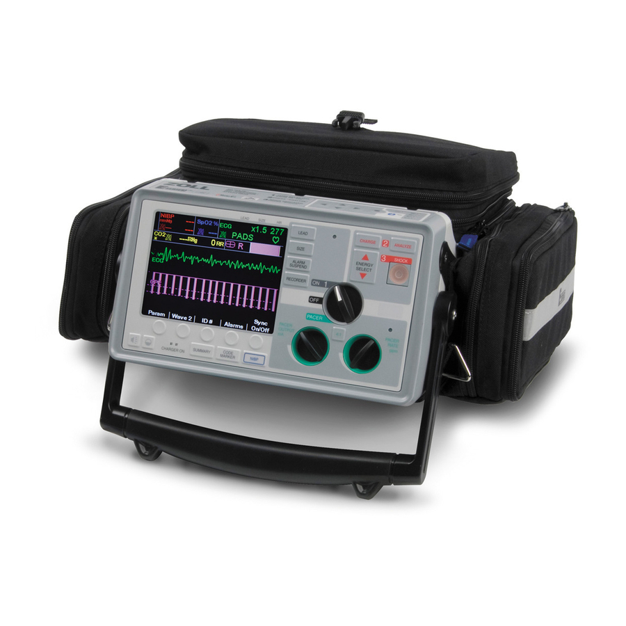
- Page 1 ZOLL E Series Defibrillator Operators Guide Get an original copy of the ZOLL E Series Defibrillator Operators Guide for manufacturer information about service, available accessories and how to use and maintain your device.
- Page 2 E Series Operator’s Guide ® 9650-1210-01 Rev. T...
- Page 3 The issue date for the E Series Operator's Guide (REF 9650-1210-01 Rev. T) is June, 2014. If more than 3 years have elapsed since this date, contact ZOLL Medical Corporation to determine if additional product information updates are available. Copyright © 2014 by ZOLL Medical Corporation. All rights reserved. AutoPulse, Base Power Charger,...
-
Page 4: Table Of Contents
FDA Regulations ....................1-15 Tracking Requirements ..................1-15 Notification of Adverse Events ................1-15 Software License....................1-15 Service ......................... 1-15 Returning a unit for service ................1-15 The ZOLL Serial Number ..................1-16 9650-1210-01 Rev. T E Series Operator’s Guide... - Page 5 E Series Operator’s Guide SECTION 2 OPERATING CONTROLS AND INDICATORS ........2-1 Code Markers ......................2-4 Summary Report Function..................2-4 Summary Report Formats..................2-4 Defibrillation Format.....................2-5 Pacer Format (Pacer version only) ..............2-6 Heart Rate Alarm Activated Format ..............2-7 VF Alarm Activated Format (Refer to Section 6)..........2-7 Recorder On Format ....................2-7...
- Page 6 5-Lead Monitoring....................10-5 Changing from 3-Lead Monitoring ..............10-5 Changing from 5-Lead ECG Monitoring.............10-5 Simultaneous 3-Lead Printing ................10-5 Vital Signs Trending ....................10-5 Viewing Vital Signs Trending Data on the Display..........10-5 Printing a Vital Signs Trend Report..............10-6 9650-1210-01 Rev. T E Series Operator’s Guide...
- Page 7 Manual Method ....................11-5 Automated Dial-up Method ................11-5 GPS Synchronization..................11-6 Operator’s Shift Checklist for E Series Products (Manual)......11-7 Operator’s Shift Checklist for E Series Products (Semiautomatic) ....11-8 SECTION 12 BATTERY MANAGEMENT ............... 12-1 Battery Care......................12-1 Battery Life Expectancy ..................12-1 LOW BATTERY Message..................12-1...
- Page 8 Guidance and Manufacturer’s Declaration — Electromagnetic Emissions ..A-7 Electromagnetic Immunity Declaration (EID) ............. A-8 EID for Life-Support Functions ................A-9 Recommended Separation Distances from RF Equipment for E Series Life-Support Functions ..................A-10 EID for Non-Life-Support Functions ..............A-11 Recommended Separation Distances from RF Equipment for E Series Non-Life-Support Functions ................
- Page 9 (This page intentionally left blank.)
-
Page 10: General Information
(DC) mains and an easily replaced battery pack that is quickly recharged in the device when it is connected to AC or DC mains. In addition, the unit’s batteries may be recharged and tested using ZOLL Base Power Charger™ 4X4 or ZOLL SurePower™... -
Page 11: How To Use This Manual
How to Use This Manual The E Series Operator's Guide provides information operators need to know for the safe and effective use and care of the E Series products. Before operating this device, be sure to read and understand all the information contained within. - Page 12 PCMCIA Data Cards (2 per package) 8000-0551 (8Mb) 8000-0552 (16Mb) 8000-0553 (32Mb) RS232 Data Transfer Cable 8000-0605-01 ECG Simulator 8012-0206 * The terms “ZOLL Multi-Function Electrode (MFE) Pads” and “MFE Pads” are used interchangeably throughout this manual. 9650-1210-01 Rev. T...
-
Page 13: Symbols Used On The Equipment
E Series Operator’s Guide Symbols Used on the Equipment Any or all of the following symbols may be used in this manual or on this equipment: Type B equipment. Type BF equipment. Type CF equipment. Defibrillator-proof type BF equipment. Defibrillator-proof type CF equipment. - Page 14 General Information Contains lead. Recycle or dispose of properly. Keep away from open flame and high heat. Do not open, disassemble, or intentionally damage. Do not crush. Nonrechargeable battery Do not discard in trash. Recycle or dispose of properly. Date of manufacture. Use by.
- Page 15 E Series Operator’s Guide Manufacturer. Authorized representative in the European Community. Serial Number. Catalogue number. Consult instructions for use. Protected against ingress of solid foreign objects > 2.5 mm in diameter. IP34 Protected against splashing water. 9650-1210-01 Rev. T...
-
Page 16: Defibrillator Function
In Manual mode, the E Series unit may also be used for analyzing the ECG. If you are using the device in an synchronized cardioversion to terminate atrial fibrillation... -
Page 17: External Pacemaker Function (Pacer Version Only)
(asystole) ensues, you should use the The unique design of the E Series products allow clear pacemaker. viewing and interpretation of the electrocardiogram Ventricular or supraventricular tachycardias may be... -
Page 18: Pediatric Pacing
Poor adherence and/or air under the MFE Pads can Multi-Function Electrode (MFE) Pads. lead to the possibility of arcing and skin burns. The pacer version of the E Series paces using ZOLL MFE Pads. 3. Open the pad packaging and apply one edge of the pad securely to the patient. -
Page 19: Monitor
CHARGER ON indicators remain extinguished. If your lead selections — I, II, III, aVR, aVL, aVF, V (with • E Series unit does not function as expected, refer to the ECG cable), PADDLES, or PADS (APLS if connected “Troubleshooting Guidelines” on page 13-1. -
Page 20: Safety Considerations
General Information Safety Considerations The E Series products are high energy devices capable of delivering up to 200 joules. To completely deactivate the device, you must turn the selector switch to the OFF position. • In order to disarm a charged defibrillator, do one of the following: Turn the selector switch to MONITOR, OFF or... -
Page 21: Operator Safety
R-wave synchronization. • The E Series device may not perform to specifications when stored at the upper or lower extreme limits of storage temperature and immediately put into use. Avoid using the E Series adjacent to, or stacked on, other equipment. If unavoidable, verify that the E Series •... -
Page 22: Cautions
General Information • The AutoPulse Plus is only intended for use on adults 18 years of age or older. When using the E Series and AutoPulse Plus as a system, this age restriction applies to the E Series as well. -
Page 23: Restarting The Device
E Series Operator’s Guide Restarting the Device Certain events require the E Series products to be restarted after they shut off or become inoperative. One example is when the battery runs down and the unit shuts off. In this case, perform these steps in this order: 1. -
Page 24: Fda Regulations
Fax: (978) 421-0010 Returning a unit for service Tel: (978) 421-9655 Before sending a unit to the ZOLL Technical Service Notification of Adverse Events Department for repair, obtain a service request (SR) Under the Safe Medical Devices Act (SMDA), health number from the service representative. -
Page 25: The Zoll Serial Number
• A product serial number of six or more alphanumeric characters The product code for the E Series defibrillator is AB. The first two characters of the date-of-manufacture code give the last two digits of the year (for example, “06”... -
Page 26: Operating Controls And Indicators
SECTION 2 OPERATING CONTROLS AND INDICATORS 11 12 13 17 18 ZM-04-36 Rev. A 1. Selector Switch Allows selection of OFF, MONITOR, DEFIB, and PACER, (Pacer version only) modes. 2. ENERGY SELECT Buttons Allows selection of defibrillation energy level. There are two sets of up-down arrow buttons; one set located on the front panel and the other (not shown) located on the sternum paddle. - Page 27 DEFIB or MONITOR mode and MFE Pads 13. CHARGER ON Indicators or Paddles are connected to the Multi-Function cable. When the E Series unit is plugged into AC mains, the Lead II is automatically selected when the E Series unit CHARGER ON indicators operate as described powers up in PACER mode (Pacer version only).
- Page 28 21. Microphone (Optional) Located on top of the unit, the recorder compartment Records audio activity in the vicinity of the E Series unit holds the paper supply for the recorder. Open the cover for storage on the PCMCIA data card.
-
Page 29: Code Markers
When you press the CODE MARKER button on the front panel, the unit displays a preconfigured list of clinical Note: Diagnostic bandwidth recordings are not included actions. See the E Series Configuration Guide (part in the summary report function. number 9650-1201-01) for information on configuring Summary Report records each event in chronological code markers. -
Page 30: Defibrillation Format
Operating Controls and Indicators as well as space for patient name, date and comments. On the last event recorded, “SUMMARY COMPLETE” is printed at the bottom left of the recorder strip. Defibrillation Format The summary report function records 6 seconds of pre-shock and 9 seconds of post-shock patient ECG data. Also recorded are joules selected, joules delivered, sync if active (includes sync markers), ECG lead, ECG size, patient impedance, actual event time and date. -
Page 31: Pacer Format (Pacer Version Only)
E Series Operator’s Guide Pacer Format (Pacer version only) The summary report function records 6 seconds of pre-pacer patient ECG data. Also recorded are the ECG lead, ECG size, patient's heart rate, actual event time and date. The date/time printed on the top of the strip corresponds to the ECG data occurring 6 seconds before the event. -
Page 32: Heart Rate Alarm Activated Format
Operating Controls and Indicators Heart Rate Alarm Activated Format The summary report function records 6 seconds of pre-alarm patient ECG. Also recorded are the ECG lead, ECG size, patient's heart rate, actual event time, and date. The date/time printed on the top of the strip corresponds to the ECG data occurring 6 seconds before the event. -
Page 33: Analyze Format
E Series Operator’s Guide and pacing current are also recorded. If async pace is active, the annotation “ASYNC PACE” is recorded. AED units additionally include shock count and AED mode annotations. Actual event date/time Analyze Format The summary report function records six seconds of pre analysis ECG and 12 seconds of ECG recorded during the ECG analysis interval with the annotation “SHOCK ADVISED”... -
Page 34: Manual Mode Activated
3. Use the scroll keys on top of the unit to scroll through the list of start times associated with different calls. AED versions of the E Series will record a “MANUAL MODE STARTED” summary report event when the device is switched from Semiautomatic mode to Manual... -
Page 35: Adding A Patient Name And Id Number To A Report
E Series Operator’s Guide • Manual mode started (AED only) • Select the Enter ( ) key from the keypad and • Alarms triggered press the Commit ( ) key on top of the unit. • Code markers The highlight automatically advances to the •... -
Page 36: Modifying A Patient Name And Id Number
Operating Controls and Indicators Note: You cannot add a patient name to summary 5. When you have modified the patient name, move the report events already stored in memory. The cursor to the Enter ( ) key on the keypad and press patient name is stored only with those summary the Commit ( ) key on top of the unit. - Page 37 E Series Operator’s Guide (This page intentionally left blank.)
-
Page 38: Manual Defibrillation
• The AutoPulse Plus is only intended for use on adults 18 years of age or older. When using the E Series and AutoPulse Plus as a system, this age restriction applies to the E Series as well. You can perform manual defibrillation using either paddles or MFE pads;... - Page 39 The ENERGY INCREMENTED message appears when this occurs. This function is disabled if you manually change the energy level outside the pre- programmed sequence and deliver a shock. See the E Series Configuration Guide for more details. 9650-1210-01 Rev. T...
- Page 40 Manual Defibrillation Charge Defibrillator Deliver SHOCK Press the CHARGE button on the front panel (if using WARNING MFE pads) or on the apex paddle handle (if using • Warn all persons in attendance of the patient to paddles). STAND CLEAR prior to defibrillator discharge. Do not touch the bed, patient, or any equipment •...
-
Page 41: Troubleshooting
Paddle plates and handles must be thoroughly cleaned after each use. See “General Maintenance” on page 11- 1 for correct cleaning procedure. Troubleshooting If your E Series unit does not function as expected, see“Troubleshooting Guidelines” on page 13-1. 9650-1210-01 Rev. T... -
Page 42: Advisory Defibrillation
The AutoPulse Plus is only intended for use on adults 18 years of age or older. When using the Begin CPR following medical protocols E Series and AutoPulse Plus as a system, this age Request additional assistance. restriction applies to the E Series as well. - Page 43 CPR or other cardiopulmonary life support and re- shock. See the “Energy Level” sections (for Shock 1, analyze the ECG at appropriate intervals. Shock 2, and Shock 3) of the E Series Configuration Guide for more details. When a shockable rhythm is detected (ventricular fibrillation or tachycardia with heart rate >...
-
Page 44: Shock Advised
Alar ms On/Off probability that the current ECG rhythm will be The E Series unit can be configured to use the Shock successfully converted by an immediate defibrillation Conversion Estimator for as many as the first four ECG shock. When the probability that a shock will be Rhythm Analyses after the unit is powered on. -
Page 45: Advisory Function Messages
Note: Reanalysis of the ECG rhythm, either manually or The prompt persists as long as a shockable rhythm is automatically (see E Series Configuration Guide), being detected. Press the ANALYZE button to begin is inhibited for 3 seconds after a shock. -
Page 46: Troubleshooting
This voice prompt is issued only if MFE pads were previously connected to the patient. Troubleshooting If your E Series unit does not function as expected, see the Defibrillator Troubleshooting section starting on page 13-5. 9650-1210-01 Rev. T... - Page 47 E Series Operator’s Guide (This page intentionally left blank.)
-
Page 48: Automated External Defibrillator (Aed) Operation
18 years of age or older. When using the resumes operation and displays and announces a E Series and AutoPulse Plus as a system, this age CHECK PATIENT prompt if a shockable rhythm is restriction applies to the E Series as well. -
Page 49: Aed Semiautomatic Operation
9650-0720-01) for instructions on properly configured a different energy level, you may select it by connecting the E Series to the AutoPulse Plus. It is using the ENERGY SELECT arrow buttons. The new recommended that the user cycle through the lead energy setting is displayed on the monitor. -
Page 50: Operating Messages
3 seconds after a shock. defibrillator is charged and ready once a decision Continue Patient Care to shock has been made. The E Series will not automatically disarm the defibrillator if the Continue patient care according to medical protocols. - Page 51 E Series Operator’s Guide ready for operation. Additional tone signals are • ECG TOO LARGE/RETRY ANALYSIS described below. These messages appear when the ECG signal is too large for proper rhythm analysis. Press the The messages that appear on the monitor depend upon ANALYZE button again to begin ECG analysis.
-
Page 52: Aed Manual Mode Operation
• “NonInvasive Temporary Pacing (Pacer Version Only)” on page 9-1 • “ECG Monitoring” on page 10-1 Troubleshooting If your E Series unit does not function as expected, see the “Troubleshooting Guidelines” on page 13-1. 120J SEL. 00:01 Manual Param Mode... - Page 53 E Series Operator’s Guide (This page intentionally left blank.)
-
Page 54: Synchronized Cardioversion
Prior to attempting synchronized cardioversion, ensure that the ECG signal quality is sufficient to minimize risk of synchronizing on artifact. • Synchronized cardioversion is disabled when the E Series unit is connected to the AutoPulse Plus and the AutoPulse Plus is compressing. Certain arrhythmias, such as ventricular tachycardia •... - Page 55 E Series Operator’s Guide Turn Selector Switch to MONITOR Press the SYNC softkey again to reactivate SYNC mode. Changing the selected energy does not turn off Sync mode. You can configure the unit to stay in Sync mode after defibrillation if desired.
-
Page 56: Troubleshooting
The charge ready tone then stops and the defibrillator remains in SYNC mode. Troubleshooting If your E Series unit does not function as expected, see the Defibrillator Troubleshooting section starting on page 13-5. 9650-1210-01 Rev. T... - Page 57 E Series Operator’s Guide (This page intentionally left blank.)
-
Page 58: Real Cpr Help
8 years of age. • The CPRD-to-MFC connector is intended for use with the E Series, or other ZOLL defibrillators where indicated. • Real CPR Help is disabled when using CPR-D-padz through an AutoPulse Plus. -
Page 59: Cpr Compressions Indicator
(fully release) their hands from the patient’s chest after compressions to allow full recoil. rate or depth, the E Series will display the letter R for Rate and/or the letter D for depth to assist the rescuer in By default, the FULLY RELEASE text prompt is not determining whether chest compression rate or depth enabled. -
Page 60: Displaying The Cpr Compressions Bar Graph
CPR Dashboard Whenever CPR-D-padz or CPR stat-padz are connected to the E Series unit and the CPR Dashboard is configured on, the unit illuminates the CPR Dashboard, replacing the right half of the Wave 2 display area. You Depth... - Page 61 E Series Operator’s Guide (This page intentionally left blank.)
-
Page 62: See-Thru Cpr
SECTION 8 SEE-THRU CPR WARNING • The See-Thru CPR filter works only when the E Series defibrillator is monitoring CPR in Manual mode. • The See-Thru CPR filter stops if: — Diagnostic bandwidth mode is active. — The unit is in pace mode. - Page 63 E Series Operator’s Guide The following figure shows a patient in Fine VF. It is difficult for a rescuer to discern this rhythm during CPR compressions. When the CPR filter turns on, the Fine VF rhythm becomes more obvious. FineVF...
- Page 64 See-Thru CPR The following figure shows a patient in VF, which, during compressions, is slightly more difficult to discern. When viewing this ECG, it is possible to view the underlying rhythm as the filter is able to reject all of the CPR artifact. CoarseVF Raw ECG Raw ECG...
- Page 65 E Series Operator’s Guide The following figure shows a patient in PEA, which could easily be mistaken for Fine VF because enough of the compression artifact leaks through to distort this signal. When the CPR filter turns on, the PEA is still not obvious because of the left over ripples from the CPR signal.
- Page 66 See-Thru CPR The following figure shows a patient with an organized rhythm where See-Thru CPR effectively filters out artifact created by CPR. SinusRhythm Raw ECG Raw ECG • | Filter ON Filtered ECG Filtered ECG 0:00 0:12 SinusRhythm Raw ECG Raw ECG •...
- Page 67 E Series Operator’s Guide (This page intentionally left blank.)
-
Page 68: Noninvasive Temporary Pacing (Pacer Version Only)
• Pacing must be turned off before defibrillating with a second defibrillator. Otherwise, the E Series unit may be damaged. Noninvasive Temporary Pacing Attach and connect the MFE pads This is described in “MFE Pad Application/Connection”... - Page 69 E Series Operator’s Guide The pacer rate increments or decrements by a value of Electrical Capture 2 ppm on the display when you turn the knob. Electrical capture means that the unit is delivering sufficient electrical current to stimulate the heart as seen on the ECG trace.
-
Page 70: Special Pacing Applications
Non Invasive Temporary Pacing (Pacer Version Only) by increasing the pacer output (mA) until every pacing • The MFE cable is defective. marker is immediately followed by a wide QRS complex. • MFE Pads are not connected to the Multi-Function cable. -
Page 71: Asynchronous Pacing
Carefully follow all instructions provided on electrode package. Troubleshooting If your E Series unit does not function as expected, see the troubleshooting section “Pacer (Pacer version only)” on page 13-4. 9650-1210-01 Rev. T... -
Page 72: Section 10 Ecg Monitoring
ECG leads are a defibrillation-protected Type CF patient connection. Introduction IEC Color AHA Color Placement of Electrodes You can use the E Series products for either short-term Coding Coding or long-term ECG monitoring. E Series products have built-in protection circuitry to... -
Page 73: Monitoring Electrodes Attachment
E Series Operator’s Guide Monitoring Electrodes Attachment Attach snap-on leads to electrodes and check for good contact between the electrode and the lead termination. Peel the protective backing from the ECG electrode. Be careful to keep adhesive surface free of electrolyte gel. -
Page 74: Alarms
) if available. preset at 30 bpm (bradycardia) and 150 bpm (tachycardia). Refer to the E Series Configuration Guide The E Series unit has three levels of alarms as follows: for details on setting power-up alarm limits. • High Priority — Reflects physiological parameters To set alarms: that are out of bounds. -
Page 75: Suspending And Silencing Alarms
Deactivating and Activating Alarms The unit restores the original high heart rate alarm limit when ECG monitoring resumes. To deactivate all alarms on the E Series unit, press and hold down the ALARM SUSPEND button for 3 seconds Suspending and Silencing Alarms or longer. -
Page 76: 5-Lead Monitoring
ECG Monitoring standard monitoring bandwidth when you release the set to Yes in System Configuration. Refer to the E Series RECORDER button. Configuration Guide for more information. 5-Lead Monitoring Vital Signs Trending You can perform 5-lead ECG monitoring with the Some E Series units include a vital signs trending feature appropriate ECG patient cable. -
Page 77: Printing A Vital Signs Trend Report
E Series Operator’s Guide If only one parameter is installed on the unit, the trend Data is printed on the stripchart in order of newest data screen automatically appears when you press the Trend to oldest data. Alarm conditions are indicated on the softkey. -
Page 78: Clearing Vital Signs Trend Records
ECG Monitoring Clearing Vital Signs Trend Records The unit stores at least 24 hours of normal (non-alarmed, non-NIBP) trending samples before it is overwritten. If the unit is powered down while recording trend data, the corresponding gap in time is indicated on the display by a series of asterisks in the time field and no data points in any parameter fields. - Page 79 E Series Operator’s Guide (This page intentionally left blank.)
-
Page 80: Section 11 General Maintenance
1. Open the recorder cover on top of the E Series unit. Operator's Shift Checklists are included at the end of this 2. Remove the paper (if necessary). -
Page 81: Testing The Defibrillator (Semiautomatic Mode)
SHOCK button and that it displays and announces 1. Verify adult paddles are installed and are inserted all the PRESS SHOCK prompt. the way into their holders on the side of the E Series 12. Press and hold the SHOCK button and verify unit unit. -
Page 82: Testing The Pacer (Pacer Version Only)
4. Verify that the units displays the TEST OK message and prints a stripchart of the event, noting the energy delivered and impedance data. Note: If TEST FAILED appears, contact the ZOLL Technical Service Department immediately. Testing the Pacer (Pacer Version Only) Perform these tests on all pacer-equipped units periodically. -
Page 83: Changing Recorder Paper
4. Align the paper above the open tray. The proper orientation is with the black arrows pointing up, and the word “ZOLL Medical Corporation” running along the left side, as shown. 5. Slide the paper into the tray. -
Page 84: Setting Time And Date
General Maintenance Setting Time and Date Note: The last field does not automatically scroll (wrap) to the beginning. You must press the Prev Field Check the time and date on the recorder annotation. If it softkey to enter the values for the last field. is not correct, reset the time and date (from System If you need to make corrections, press the Prev Utilities mode) manually, by dial-up to a National Institute... -
Page 85: Gps Synchronization
The modem could not dial the phone ERROR number. Ensure that the modem card is properly connected. Ensure that the user-selected dial prefix is correct. (Refer to E Series Configuration Guide for information). Retry. NIST DATA The unit detected an error in the data ERROR from NIST. -
Page 86: Operator's Shift Checklist For E Series Products (Manual)
Operator’s Shift Checklist for E Series Products (Manual) Recommended checks and procedures to be performed at the start of each shift. For more detailed information, see the E Series Operator’s Guide. Date____________________________Location________________________________Unit Serial Number__________________ 1. Condition Remarks Shift Shift Shift Unit clean, no spills, clear of objects on top, case intact 2. -
Page 87: Operator's Shift Checklist For E Series Products (Semiautomatic)
Operator’s Shift Checklist for E Series Products (Semiautomatic) Recommended checks and procedures to be performed at the start of each shift. For more detailed information, see the E Series Operator’s Guide. Date_____________________________Location __________________________Unit Serial Number ______________________ 1. Condition Remarks Shift... -
Page 88: Section 12 Battery Management
Changing the Battery Pack operation, and the pattern of discharging and recharging batteries contribute to the loss of battery charge capacity. The E Series products are designed for quick removal Because of this, ZOLL recommends that operators and replacement of the battery pack. -
Page 89: Charging And Testing Battery Packs
ZOLL Base Power Charger 4x4 or SurePower Charger was designed specifically for this purpose. With the E Series unit plugged in to AC mains and turned off, the device recharges the sealed lead acid battery to greater than 90% capacity within 4 hours, and the lithium-ion battery pack to greater than 90% capacity in less than 7 hours. -
Page 90: Achieving Optimal Battery Pack Performance
It is important to visibly distinguish battery packs that are charged from those that are not. Establish a system for visually indicating whether a battery pack is charged and ready for use or is in need of charging. ZOLL can provide you with battery pack status labels for this purpose, or you can use labels or methods of your own. - Page 91 If the device shows a LOW BATTERY warning during testing, replace the depleted battery pack with a fully charged one, and recharge the depleted battery pack. DON’T charge battery packs at temperature extremes. ZOLL recommends charging battery packs at or near normal room temperature (15°C to 35°C or 59°F to 95°F). 12-4 9650-1210-01 Rev. T...
-
Page 92: Section 13 Troubleshooting Guidelines
This section addresses many of the common problems or questions that may arise during operation. If trouble persists after consulting this guide, contact the appropriate technical personnel or ZOLL Technical Service Department. A more detailed troubleshooting guide is found in the E Series Service Manual. - Page 93 AutoPulse Plus, if in use, and plug the multifunction cable directly into the electrode pads. Noisy ECG, artifact, wandering baseline • Consider 1 – 21Hz filter bandwidth (see E Series Configuration Guide). • Prepare the patient’s skin prior to electrode attachment.
-
Page 94: Recorder
Recorder makes stuttering sound when activated. Check recorder for paper jam. • Light or poor quality printing is observed. Ensure correct paper type (ZOLL P/N 8000-0300) is in • use. • Ensure paper is installed grid-side against recorder print head. -
Page 95: Pacer (Pacer Version Only)
E Series Operator’s Guide Pacer (Pacer version only) Symptom Recommended Action Unit displays the CHECK PADS prompt. Ensure MFE Pads are connected to Multi-Function • cable. • Ensure electrode gel is not dry. Replace MFE Pads if necessary. Ensure good electrode-to-patient contact. -
Page 96: Defibrillator
Troubleshooting Guidelines Defibrillator Symptom Recommended Action Excessive artifact when using paddles as ECG source. • Ensure PADDLES is selected. • Firmly press paddles against patient skin. • Use gel on paddles. • Clean paddle surface. • Check and clean between adult and pediatric shoe. •... - Page 97 Unit displays the DEFIB MAINT. REQUIRED message. • Contact ZOLL Technical Service Department. Unit displays a DEFIB FAULT XX message. If problem persists, contact ZOLL Technical Service • Department. 13-6 9650-1210-01 Rev. T...
-
Page 98: Ac Charger
Troubleshooting Guidelines AC Charger Symptom Recommended Action The green and orange-yellow CHARGER ON indicators • Verify battery is installed. illuminate alternately. • Turn unit ON to identify the fault condition. • Replace battery pack with a fully charged battery pack. •... - Page 99 E Series Operator’s Guide (This page intentionally left blank.)
-
Page 100: Appendix Aspecifications
Operating: 0C to 55C (32F to 131F) Storage Temperature: -20 to 60C (-4F to 140F) Note: The E Series device may not perform to specifications when stored at the upper or lower extreme limits of storage temperature and immediately put into use. -
Page 101: Pacemaker (Pacer Version
Variable from 30 ppm to 180 ppm ±1.5% (increments or decrements by a value of 2 ppm) Output protection Fully defibrillator protected and isolated Specifically designed adult anterior/posterior pre-gelled ZOLL MFE Pads and Multi-Function Electrode (MFE) Multi-Function stat-padz packaged in pairs... -
Page 102: Ecg Monitoring
0.1ms and 2ms, without overshoot, and between ±100mV and ±500mV, with widths between 0.1ms and 2ms, with overshoot from 4 to 100ms. The pacemaker pulse rejection capability for the E Series with pacemaker pulses and a normally paced QRS and T wave includes pulses between ±2mV and ±700mV amplitude, with widths between 0.1ms and 2ms, without overshoot, and between ±2mV... -
Page 103: Cpr Monitoring
The E Series averages the interval between the last 5 detected beats. On startup, the Averaging E Series averages the rate between detected beats once two beats are detected, until a full 5 beats have been received. The rate is updated every beat. After this condition is met, the meter is updated every beat with an average of the last 5 beats. -
Page 104: Display
Display Screen Type High resolution, color liquid crystal display (LCD) Screen Size 5.63 inches (14.3 cm) diagonally Sweep Speed 25 mm/s Viewing Time 4 seconds Messages ERASING REPORT, INSERT CARD, CARD FULL, REPLACE BATTERY, LOW BATTERY, PERFORM CPR, ECG TOO LARGE, NOISY ECG, RETRY ANALYSIS, CHECK PATIENT, ANALYSIS HALTED, PRESS ANALYZE, NO SHOCK ADV., CHECK PULSE, SHOCK ADVISED, PRESS CHARGE, SELECT PADS, SELECT ECG LEADS, SELECT DEFIB MODE, VF ALARMS OFF, DISABLE SYNC, ANALYSIS RESTARTED,... - Page 105 Standby Life: one month before retest and recharge. Note: Each monitoring option added to the E Series device decreases the Operating Time that can be obtained from a fully charged battery. Refer to the individual option insert for the operating run time specific to your device. For further details specific to your device, contact the ZOLL Technical Service Department.
-
Page 106: Guidance And Manufacturer's Declaration - Electromagnetic Emissions
Guidance and Manufacturer’s Declaration Electromagnetic Emissions — The E Series unit is intended for use in the electromagnetic environment specified below. Ensure that the E Series unit is used in such an environment. Emissions Test Compliance Electromagnetic Environment — Guidance RF emissions ... -
Page 107: Electromagnetic Immunity Declaration (Eid
If the user 40% U (60% dip in U 40% U (60% dip in U supply input lines of the E Series unit requires for 5 cycles for 5 cycles IEC 61000-4-11 continued operation during 70% U (30% dip in U... -
Page 108: Eid For Life-Support Functions
To assess the electromagnetic environment due to fixed RF transmitters, an electromagnetic site survey should be considered. If the measured field strength in the location in which the E Series unit is used exceeds the applicable RF compliance level above, the E Series unit should be observed to verify normal operation. If abnormal performance is observed, additional measures may be necessary, such as reorienting or relocating the E Series unit. -
Page 109: Recommended Separation Distances From Rf Equipment For E Series Life-Support Functions
The life-support functions on the E Series unit are defined to be any function associated with Pacing and Defibrilla- tion. Specifically, these functions include, but are not limited to, the pacing pulse output and defibrillation energy dis- charge. -
Page 110: Eid For Non-Life-Support Functions
To assess the electromagnetic environment due to fixed RF transmitters, an electromagnetic site survey should be considered. If the measured field strength in the location in which the E Series unit is used exceeds the applicable RF compliance level above, the E Series unit should be observed to verify normal operation. If abnormal performance is observed, additional measures may be necessary, such as reorienting or relocating the E Series unit. -
Page 111: Recommended Separation Distances From Rf Equipment For E Series Non-Life-Support Functions
The non-life-support functions on the E Series unit are defined to be any function not listed as a life-support function in the “EID for Life Support Functions” table (Note a). Specifically, these functions are noninvasive blood pressure... -
Page 112: Rectilinear Biphasic Waveform Characteristics
(VT) defibrillation study. This study (which was conducted using ZOLL M Series defibrillators) and the findings are described below. Since the E Series unit's rectilinear biphasic waveform employs the same first and second phase timing, the same first and second phase currents/voltages and essentially the same mechanisms for controlling defibrillation waveshape, the ZOLL M Series and ZOLL E Series defibrillation waveforms are considered equivalent. - Page 113 ±15% Figures A-1 through A-20 show the rectilinear biphasic waveforms that are produced when the E Series defibrillator is discharged into loads of 25, 50, 75, 100, 125, 150, and 175 ohms at each energy setting (200, 150, 120, 100, 85, 70, 50, 30, 20, 15, 10, 9, 8, 7, 6, 5, 4, 3, 2 and 1 joule[s]).
- Page 114 25Ω 50Ω 75Ω 100Ω 125Ω 150Ω 175Ω Figure A-1. Rectilinear Biphasic Waveforms at 200 Joules 25Ω 50Ω 75Ω 100Ω 125Ω 150Ω 175Ω Figure A-2. Rectilinear Biphasic Waveforms at 150 Joules 25Ω 50Ω 75Ω 100Ω 125Ω 150Ω 175Ω Figure A-3. Rectilinear Biphasic Waveforms at 120 Joules 9650-1210-01 Rev.
- Page 115 E Series Operator’s Guide 25Ω 50Ω 75Ω 100Ω 125Ω 150Ω 175Ω Figure A-4. Rectilinear Biphasic Waveforms at 100 Joules 25Ω 50Ω 75Ω 100Ω 125Ω 150Ω 175Ω Figure A-5. Rectilinear Biphasic Waveforms at 85 Joules 25Ω 50Ω 75Ω 100Ω 125Ω 150Ω...
- Page 116 25Ω 50Ω 75Ω 100Ω 125Ω 150Ω 175Ω Figure A-7. Rectilinear Biphasic Waveforms at 50 Joules 25Ω 50Ω 75Ω 100Ω 125Ω 150Ω 175Ω Figure A-8. Rectilinear Biphasic Waveforms at 30 Joules 25Ω 50Ω 75Ω 100Ω 125Ω 150Ω 175Ω Figure A-9. Rectilinear Biphasic Waveforms at 20 Joules 9650-1210-01 Rev.
- Page 117 E Series Operator’s Guide 25Ω 50Ω 75Ω 100Ω 125Ω 150Ω 175Ω Figure A-10. Rectilinear Biphasic Waveforms at 15 Joules 25Ω 50Ω 75Ω 100Ω 125Ω 150Ω 175Ω Figure A-11. Rectilinear Biphasic Waveforms at 10 Joules 25Ω 50Ω 75Ω 100Ω 125Ω 150Ω...
- Page 118 25Ω 50Ω 75Ω 100Ω 125Ω 150Ω 175Ω Figure A-13. Rectilinear Biphasic Waveforms at 8 Joules 25Ω 50Ω 75Ω 100Ω 125Ω 150Ω 175Ω Figure A-14. Rectilinear Biphasic Waveforms at 7 Joules 25Ω 50Ω 75Ω 100Ω 125Ω 150Ω 175Ω Figure A-15. Rectilinear Biphasic Waveforms at 6 Joules 9650-1210-01 Rev.
- Page 119 E Series Operator’s Guide 25Ω 50Ω 75Ω 100Ω 125Ω 150Ω 175Ω Figure A-16. Rectilinear Biphasic Waveforms at 5 Joules 25Ω 50Ω 75Ω 100Ω 125Ω 150Ω 175Ω Figure A-17. Rectilinear Biphasic Waveforms at 4 Joules 25Ω 50Ω 75Ω 100Ω 125Ω 150Ω...
-
Page 120: Clinical Trial Results For The Biphasic Waveform
Figure A-20. Rectilinear Biphasic Waveforms at 1 Joules Clinical Trial Results for the Biphasic Waveform The efficacy of ZOLL’s Rectilinear Biphasic waveform has been clinically verified during a study of defibrillation of Ventricular Fibrillation (VF)/Ventricular Tachycardia (VT). A feasibility study was performed initially for defibrillation of VF/VT (n=20) on two separate groups of patients to ensure waveform safety and energy selection. -
Page 121: Randomized Multi-Center Clinical Trial For Cardioversion Of Atrial Fibrillation (Af)
A total of 173 patients entered the study. Seven (7) patients who did not satisfy all protocol criteria were excluded from the analysis. ZOLL disposable gel electrodes with surface areas of 78 cm (anterior) and 113 cm (posterior) were used exclusively for the study. -
Page 122: Synchronized Cardioversion Of Atrial Fibrillation
between the two waveforms were considered statistically significant when the 95% confidence interval between the two waveforms was greater than 0%. Results: The study population of 165 patients had a mean age of 66±12 years with 116 male patients. The total efficacy of consecutive rectilinear biphasic shocks was significantly greater than that of monophasic shocks. The following table displays the Kaplan-Meier (product-limit) survival curves for each of the two waveforms. -
Page 123: Shock Conversion Estimator
SCE Level settings (HIGH, MEDIUM, and LOW) and corresponding SPI thresholds, sensitivities, and specificities that can be configured on the E Series unit. Column 1 is the SPI threshold in mv-Hz. Columns 2 and 3 are the sensitivity and specificity as described below (expressed in percent). - Page 124 Number of ECG Rhythms with SPI > Threshold that were successfully converted Sensitivity = ------------------------------------------------------------------------------------------------------------- Total number of ECG rhythms that were successfully converted Number of ECG rhythms with SPI Threshold that did not convert Specificity = ----------------------------------------------------------------------------------------- Total number of ECG rhythms that did not convert Figure A-21.
- Page 125 E Series Operator’s Guide Table A-2. Accuracy Table of SCE Levels and Corresponding SPI Thresholds SCE Level SPI Threshold Sensitivity Specificity (mV-Hz) HIGH MEDIUM 10.8 References: [1] Eftestol T, Sunde K, Steen PA. Effects of Interrupting Precordial Compressions on the Calculated Probability of Defibrillation Success during Out-of-Hospital Cardiac Arrest.
-
Page 126: Ecg Analysis Algorithm Accuracy
The data in the following table summarizes the accuracy of the ECG analysis algorithm as tested Clinical Performance Results against ZOLL’s ECG Rhythm Database. The performance of the incorporated analysis algorithm The algorithm sequence takes approximately 9 seconds in a single analysis sequence satisfies the applicable... - Page 127 E Series Operator’s Guide (This page intentionally left blank.)
-
Page 128: Appendix B Medical Report Capability
5. Press the Enter softkey. You can store up to two hours of incident data (ECG and The E Series unit erases the card and displays the unit status) or up to 38 minutes of incident data and ERASING CARD message. A progress bar appears simultaneous audio recording on one 4-megabyte while erasing the card. -
Page 129: Transferring Data To A Pc With A Pcmcia Data Card Reader
Some E Series units include a wireless communication remote handheld device or PC to access any data option that uses Bluetooth technology to communicate transmitted from the E Series unit. Refer to the ZOLL with a ZOLL-approved, Bluetooth-equipped host system Data Relay user documentation for installation and (handheld device or PC running ZOLL Data Relay operating instructions. -
Page 130: Communication Settings
You must configure the same communication settings on Upload both the E Series unit and the PC or hand-held device for proper data transmission. The correct communication settings are: [008] 12 FEB 10 06:25:37... -
Page 131: Activating Automatic Data Transmission
Param Wave 2 Alarms 12 Lead In realtime mode, the E Series unit only transmits trend data collected since the unit was powered-up, and does MONITOR NOT transmit all trend data stored in memory. To transmit all trend data, you must initiate transmission... -
Page 132: Transmitting 12-Lead Patient Records
Phone# softkey. If you are transmitting via Bluetooth, then the green 1. With the E Series unit in Monitor mode (ON for AED power LED on the E Series unit illuminates. You must units), press the 12 Lead softkey to access the 12 now establish a connection between the host system Lead menu. - Page 133 The unit operates, but no data is Wait for E Series events to clear being stored. and retry. Erasing the card may allow return Ensure remote device is on and to normal data storage operation ready to accept data.
Need help?
Do you have a question about the E Series and is the answer not in the manual?
Questions and answers