
Related Manuals for Landoll Brillion XXL38-46


Summary of Contents for Landoll Brillion XXL38-46
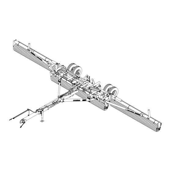
- Page 1 ‘ XXL Pulverizer Models XXL38-46 Operator’s Manual LANDOLL COMPANY, LLC 1900 North Street Marysville, Kansas 66508 (785) 562-5381 800-428-5655 ~ WWW.LANDOLL.COM F-794-2406...
- Page 2 Manuals for XXL Pulverizer - 38' thru 46' Manual Number Manual Type F-794 Operator’s Manual F-793 Parts Manual...
- Page 3 DANGER DO NOT operate or perform any maintenance tasks on this equipment until you have completed the following: 1. Receive proper training to operate this equipment safely. 2. Read and understand the operator’s manual. 3. Be thoroughly trained on inspection and repair procedures. Failure to comply with this warning may result in serious injury or possibly death.
- Page 5 Table of Contents Safety Introduction ............1-1 Description of Unit .
- Page 6 TABLE OF CONTENTS Operation Tractor Preparation..........3-1 Pulverizer Preparation .
- Page 7 Failure to comply with this warning can result in within 10 days of retail purchase, using the Landoll personal injury or death, damage to the Corporation Ag Products on-line registration process.
- Page 8 TABLE OF CONTENTS SAFETY Safety • When applying decals to the implement, be sure to clean the surface to remove any dirt or residue. Where possible, sign placement should protect the NOTE sign from abrasion, damage, or obstruction from Investigation has shown that nearly 1/3 of all farm mud, dirt, oil etc.
- Page 9 TABLE OF CONTENTS SAFETY Safety Instructions for Towing Maintenance Safety Vehicles • Block the machine so it will not roll when working on or under it. The maximum travel speed is the lesser of • Make sure Transport Lock is installed and secured. •...
- Page 10 TABLE OF CONTENTS SAFETY High Pressure Fluid Safety Bolt, Escaping fluid under pressure can be nearly invisible and Hitch Lock Tractor 1-8 x 2-1/2 have enough force to penetrate the skin causing serious Drawbar injury. Use a piece of cardboard, rather than hands, to search for suspected leaks.
- Page 11 ITEM 6 2-573-010198 ITEM 7 - 6J999 ITEM 8 - 9J629 ITEM 9 ITEM 10 ITEM 11 528933 528934 528938 A LANDOLL PRODUCT PULVERIZER ITEM 12 - 170510 mile/h 144193 ITEM 15 ITEM 14 A LANDOLL PRODUCT P/N: 232188 2P151...
- Page 12 TABLE OF CONTENTS SAFETY Figure 1-5: Decal Locations, Center (2 of 5) F-794-2406...
- Page 13 TABLE OF CONTENTS SAFETY FRONT VIEW 11, 12 and 13 FT RH Wings XXL38, XXL40 and XXL42 Models REAR VIEW 11 FT RH Wings XXL38 Models FRONT VIEW 14 and 15 FT RH Wings XXL44 and XXL46 Models REAR VIEW 12, 13, 14 and 15 FT RH Wings XXL40, XXL42, XXL44 and XXL46 Models XXL38-46 DecalRHWing...
- Page 14 TABLE OF CONTENTS SAFETY FRONT VIEW REAR VIEW 11, 12 and 13 FT LH Wings XXL38, XXL40 and XXL42 Models FRONT VIEW REAR VIEW 14 and 15 FT LH Wings XXL44 and XXL46 Models Figure 1-7: Decal Locations, Left Hand Wing (4 of 5) F-794-2406...
- Page 15 TABLE OF CONTENTS SAFETY RH WING REAR VIEW LH WING REAR VIEW XXL38-46 DecalOptimizerWing Figure 1-8: Decal Locations, Optimizer Wings (5 of 5) F-794-2406...
- Page 16 TABLE OF CONTENTS SAFETY Table provided for general use. NOTES: 1-10 F-794-2406...
- Page 17 Chapter 2 TABLE OF CONTENTS Assembly IMPORTANT CAUTION All Harnesses must be firmly attached to machine Do Not work on or under this machine unless frame members or Hydraulic Hoses so they do not securely blocked and supported by a hoist or sag or become torn loose by field debris.
- Page 18 TABLE OF CONTENTS ASSEMBLY Frame and Transport Axle Tire and Wheel Installation Assembly WARNING 1. Position the Transport Axle on a level surface under the designated frame assembly area. See Use a torque wrench to assure proper torque. Figure 2-2. Insufficient torque can cause stud breakage and damage the wheel pilots.
- Page 19 TABLE OF CONTENTS ASSEMBLY Locknut,5/16-18 Locknut,5/8-11 Flat Washer,5/8 Flat Washer,5/16 Center Frame Bolt, 5/16-18 x 1 Bearing Insert Bearing Half Bearing Half Bearing Insert Transport Axle Bolt, 5/8-11 x 11 Wheel Asm Wheel Bolt, 1/2-20 x 1 Figure 2-2: Frame and Transport Axle F-794-2406...
- Page 20 TABLE OF CONTENTS ASSEMBLY Transport Lock Installation 4. Attach the Cylinder Rod End Clevis to the Transport Axle Lift Arm with 1-1/4 x 12-7/8 Pin. Slide a 1-3/4 x 1. Slide 1-1/4 x 2-11/16 Bushing into the base end of the 4-5/8 Tube on each side of the cylinder clevis.
- Page 21 TABLE OF CONTENTS ASSEMBLY Center Roller Assembly Installation Rotation Arrow must follow the direction 1. Roller Assemblies are pre-assembled from the of travel factory with stub shafts, bearings, shims, and retaining washers. NOTE: Crowfoot Wheel Rotation Arrow must follow the direction of travel. See Figure 2-4.
- Page 22 TABLE OF CONTENTS ASSEMBLY Figure 2-5: Trunnion Spacers F-794-2406...
- Page 23 TABLE OF CONTENTS ASSEMBLY Flat Top Washer Bolt,3/4-10 x 2-1/4 Washer,3/8 Thick Lock Washer,3/4 Bolt,1-8 x 2-1/4 Lock Washer,1" Trunnion Bearing Mount Shim Washer,11ga Trunnion Washer Trunnion Bearing Center Roller Shim Washer, 14ga Shim Washer, 11ga Figure 2-6: Center Roller Assembly Installation F-794-2406...
- Page 24 TABLE OF CONTENTS ASSEMBLY Drawbar and Brace 2. Secure the Drawbar end with 3/4-10 x 2 Bolts and Locknuts. Do not tightens these Bolts until both Installation Drawbar Braces are assembled. Use the same procedure to assemble the Drawbar Brace on the 1.
- Page 25 TABLE OF CONTENTS ASSEMBLY Drawbar Components 3. Attach Drawbar Stop to the frame tube with 5/8-11 x 2 Bolts, Lock Washers and Nuts. The Drawbar Stop 1. Attach the Manual Canister on the top of the Drawbar limits the drawbar vertical travel. Bracket with 1/4-20 x 1 Bolts, Flat Washers, and 4.
- Page 26 TABLE OF CONTENTS ASSEMBLY Wing Cylinder Installation 1. Install the Wing Fold Hydraulic Cylinders Base End to the center frame lugs with ports facing the front of machine using the vendor supplied hardware. See Figure 2-9. 2. Block each Cylinder Rod Clevis up from the frame to allow for rod movement when purging the Hydraulic Circuit.
- Page 27 TABLE OF CONTENTS ASSEMBLY Hydraulic Installation 2. Orient the fitting by turning counterclockwise up to 1 turn. 3. Tighten the Locknut using 50-60 Ft-Lbs torque. See IMPORTANT “Hydraulic Fitting Torque Specifications” on Unfold and lower the unit to the ground and relieve page 4-2.
- Page 28 TABLE OF CONTENTS ASSEMBLY Figure 2-11: Hydraulic Layout 2-12 F-794-2406...
- Page 29 TABLE OF CONTENTS ASSEMBLY Figure 2-12: Hydraulic Schematic F-794-2406 2-13...
- Page 30 TABLE OF CONTENTS ASSEMBLY Purging the Hydraulic System DANGER DANGER IMPORTANT Falling wings can cause injury or death. Stand clear when wings are being raised or lowered. Unfold and lower the unit to the ground and relieve system pressure before attempting to repair, adjust, or disconnect components.
- Page 31 TABLE OF CONTENTS ASSEMBLY Wing to Frame Installation 2. Place 1-/1/4 end of the link on the inside of each wing frame lug. Position spacer between links. Align the 1. Position the right hand wing frame between the right holes and insert 1-1/4 x 7-11/16 Pin. Place washers center frame bushings.
- Page 32 TABLE OF CONTENTS ASSEMBLY Transport Lock Linkage NOTE Assembly Ensure Linkage is not bent or kinked. See Figure 2-15. 3. If needed, adjust the Transport Lock Linkage chain 1. Attach the linkage Bracket to the right hand wing length by repositioning the S-Hook on the chain so frame with 3/8-16 x 5 Bolt, Lock Washer and Nut.
- Page 33 TABLE OF CONTENTS ASSEMBLY Wing Roller Assembly bearing around to have snap ring to inside. The bearing inner race is offset with respect to the Installation trunnion bosses by 1/32". By installing bearings with snap rings in versus out, 1/16" difference can be 1.
- Page 34 TABLE OF CONTENTS ASSEMBLY Figure 2-17: Trunnion Spacers 2-18 F-794-2406...
- Page 35 TABLE OF CONTENTS ASSEMBLY Lock Washer,1" Thick Washer,3/8 Bolt,1-8 x 2-1/4 Flat Top Washer Trunnion Washer Shim Washer,11 ga Trunnion Bearing Bolt,3/4-10 x 2-1/4 Tunnion Bearing Mount Lock Washer,3/4 Wing Roller XXL38-46 OpWingRoller Shim Washer, Shim Washer, 14 ga 11 ga Figure 2-18: Wing Roller Assembly Installation F-794-2406 2-19...
- Page 36 TABLE OF CONTENTS ASSEMBLY Figure 2-19: V-Wheel Wing Roller Assembly Installation (XXL42, XXL44, XXL46 Models) 2-20 F-794-2406...
- Page 37 TABLE OF CONTENTS ASSEMBLY Table provided for general use. NOTES: F-794-2406 2-21...
- Page 38 TABLE OF CONTENTS ASSEMBLY Warning Lamp Installation IMPORTANT All Harnesses must be firmly attached to machine NOTE frame members or Hydraulic Hoses so they do not sag or become torn loose by field debris. Use the tie Be sure when assembling Lamps onto Brackets that the wraps provided.
- Page 39 TABLE OF CONTENTS ASSEMBLY Figure 2-20: Electrical Layout F-794-2406 2-23...
- Page 40 TABLE OF CONTENTS ASSEMBLY Center Notch Wheel Scraper - Flanged Locknuts. Adjust the Center Scraper Brackets as needed to Center the Scrapers between Optional the Notched Wheels and adjust the Scrapers so that there is a 1/4 gap between the Scraper and Notched Wheels.
- Page 41 TABLE OF CONTENTS ASSEMBLY Wing Notch Wheel Scraper - 2. Center the Scraper Tube over the length of the Wing Roller. Place the 3/8-16 U-Bolts as close as possible Optional to the Wing Scraper Mount flange bend. Assemble the Scraper Tube to the Wing Scraper Mounts with a Right Hand Shown, Left Hand similar.
- Page 42 TABLE OF CONTENTS ASSEMBLY Table provided for general use. NOTES: 2-26 F-794-2406...
- Page 43 TABLE OF CONTENTS ASSEMBLY Center V-Wheel Scraper - 3. Remove the 1/2-13 Flanged Locknuts where the corresponding U-Bolts will attach the Scraper Tube to Optional the Scraper Brackets. Center the Scrapers between the V-Wheels and mount the Scrapers and Scraper 1.
- Page 44 TABLE OF CONTENTS ASSEMBLY Wing V-Wheel Scraper, 2. The Scraper Assembly is pre-assembled with Scrapers attached to the Scraper Tube. Lay the Single Tube - Optional Scraper Assembly behind the Wing Roller so the Scrapers are outward when attached to the Wing Right Hand Shown, Left Hand similar.
- Page 45 TABLE OF CONTENTS ASSEMBLY Wing V-Wheel Scraper, 2. The Scraper Assembly is pre-assembled with Scrapers attached to the Scraper Tube. Lay the Double Tube - Optional Scraper Assembly behind the Wing Roller so the Scrapers are outward when attached to the Wing Right Hand Shown, Left Hand similar.
- Page 46 TABLE OF CONTENTS ASSEMBLY Acre Meter - Optional Bracket onto the Bearing Hanger and re-install existing Trunnion Bearing Bolts and Lock Washers. Fully tighten. IMPORTANT 5. Adjust the Acre Meter Switch so the center line of Unfold and lower machine prior to performing any Magnet Wheel and Pick-Up Switch are horizontally steps.
- Page 47 TABLE OF CONTENTS ASSEMBLY Figure 2-27: Acre Meter Installation F-794-2406 2-31...
- Page 48 TABLE OF CONTENTS ASSEMBLY Table provided for general use. NOTES: 2-32 F-794-2406...
- Page 49 Chapter 3 TABLE OF CONTENTS Operation DANGER DANGER CAUTION Never allow anyone a ride on the Pulverizer at any When transporting farm implements on public time. Allowing a person to ride on the machine can roads, it is the responsibility of the operator to inflict serious personal injury or death to that abide by state and local laws concerning wide person.
- Page 50 TABLE OF CONTENTS OPERATION Attaching to the Tractor Drawbar Positions 1. Align the Tractor Drawbar with the machine. Raise or The Drawbar is designed to be operated with the lower the hitch, as needed, using the jack. Attach the Drawbar Extension retracted or extended. The Drawbar unit with proper size hitch pin.
- Page 51 TABLE OF CONTENTS OPERATION Hitch Lock General Operation The Hitch Lock prevents the hitch from moving in either DANGER DANGER the Spade or Clevis position. Note the different orientation of the Hitch Lock. Watch out for Overhead Electrical Wires and other •...
- Page 52 TABLE OF CONTENTS OPERATION Hydraulic System DANGER DANGER IMPORTANT Falling wings can cause injury or death. Stand clear when wings are being raised or lowered. Unfold and lower the unit to the ground and relieve system pressure before attempting to repair, adjust, or disconnect components.
- Page 53 TABLE OF CONTENTS OPERATION Table provided for general use. NOTES: F-794-2406...
- Page 54 TABLE OF CONTENTS OPERATION Operation of Transport Lock Field to Road 1. Actuate the tractor hydraulic lever to raise the center and fold the wings for transport. IMPORTANT 2. When the Pulverizer is raised and folded the Be sure Transport Lock is either locked or unlocked. Transport Lock will automatically engage the lift system/cable spring link system, locking the NOTE...
- Page 55 TABLE OF CONTENTS OPERATION 3. Reverse the tractor hydraulic lever again to retract the Road to Field Lift Cylinder, lowering the machine to the ground. The 1. Actuate the tractor hydraulic lever to unfold wings Tire and Wheel Assemblies should be off the ground completely, slackening the cable/spring linkage.
- Page 56 TABLE OF CONTENTS OPERATION Drawbar Adjustment Center Frame The Pulverizer drawbar can pivot vertically in field operation to limit soil pushing. 1. Place Shims on top of the Brace if the Center Roller pushes soil and place Shims under the Brace if Wing Rollers push soil.
- Page 57 TABLE OF CONTENTS OPERATION Scraper Adjustment NOTE A scraper can be used as a guide to achieve the 1/4" gap. Notched Roller Wheel Scrapers are designed to keep the Notched Roller Wheels from building up with moist soil 1. Unfold and Lower Pulverizer on a level surface. during operation.
- Page 58 TABLE OF CONTENTS OPERATION Loup Acre Meter Kit - Total Acres Optional Press the /FUNC button until the “TOTAL” LED is lit. The digits indicate the acres covered since the total acre counter was cleared. IMPORTANT To clear the total acre count, press and hold the UP and Acre Meter is dust and splash resistant, under no DOWN buttons for two seconds.
- Page 59 TABLE OF CONTENTS OPERATION Battery Replacement If the display shows “Ent”: You must enter your password using the UP and DOWN buttons. When your The battery operated acre counter uses 3 AA batteries. password is displayed, press the /FUNC button to test The “BATT”...
- Page 60 TABLE OF CONTENTS OPERATION Transport 6. Before transporting: • Know the transport height and width of the unit 1. Check and follow all federal, state, and local before transporting. Use caution when requirements before transporting the Pulverizer. transporting near bridges and power lines. 2.
- Page 61 Chapter 4 TABLE OF CONTENTS Maintenance General Torque Specifications (rev. 4/97) This chart provides tightening torques for general purpose applications when special torques are not specified on process or drawing. Assembly torques apply to plated nuts and capscrews assembled without supplemental lubrication (as received condition). They do not apply if special graphite moly-disulfide or other extreme pressure lubricants are used.
- Page 62 TABLE OF CONTENTS MAINTENANCE Hydraulic Fitting Torque Specifications 37 degree JIC, ORS, & ORB (REV. 10/97 This chart provides tightening torques for general purpose applications when special torques are not specified on process or drawing. Assembly torques apply to plated nuts and capscrews assembled without supplemental lubrication (as received condition). They do not apply if special graphite moly-disulfide or other extreme pressure lubricants are used.
- Page 63 TABLE OF CONTENTS MAINTENANCE Tires Lubrication Maintenance Recommended Tire Size: 11L X 15 - 12 Ply • Lubricate trunnion bearings and hinge pins with quality grease per recommended lubrication Tire Inflation Pressure: 52 PSI frequency intervals indicated or if machine is not When Re-Installing 1/2-20 x 1 Wheel Bolts tighten to used for an extended period.
- Page 64 TABLE OF CONTENTS MAINTENANCE Hydraulic System 4. Transport Locks are provided to hold the implement in a raised position. See “Operation of Transport Maintenance Lock” on Page 3-6. Do not attempt to perform any service work under the implement without first installing the Transport Locks.
- Page 65 TABLE OF CONTENTS MAINTENANCE Warning Lamps When plugging in the 7-Pin Connector: Amber Amber Red Lamp 1. Make sure the tractor has a good clean receptacle, Lamp Lamp free of dirt and corrosion. 2. Make sure the 7-Pin Connector is inserted ALL the way in.
- Page 66 TABLE OF CONTENTS MAINTENANCE Roller Bearing Maintenance on the inside between the Stub Shaft shoulder and the Trunnion Bearing, all three can be on the outside If bearings are removed from frame refer to the steps between the Trunnion Bearing and Flat Top Washer, below to ensure minimum axle load is applied to prolong or a combination on either side, but all three must be bearing life.
- Page 67 TABLE OF CONTENTS MAINTENANCE Roller Axle Assembly Clamp Tightening After an initial run of 5-10 hours, check the Roller Axle Standard Wheel Roller Assemblies to ensure that the wheels are tight to one 1. Tighten the Clamp Bolts evenly to achieve equal another.
- Page 68 TABLE OF CONTENTS MAINTENANCE Clamp End Spacers - Installation is the same for either kit. 1. Place the two Axle Spacers between the Axle Clamp Optional and the Wheel Stop. See Figure 4-9. The Clamp End Spacer Kits are used to eliminate space 2.
- Page 69 TABLE OF CONTENTS MAINTENANCE Kit Part Number 204831 - 1" Axle Spacer Refer to the Torque Table for proper bolt torque values. Note the different torque requirement for Bolts with Kit Part Number 204832 - 1-1/4" Axle Spacer Locknuts. See Page 4-1. Kit Part Number 204833 - 1-1/2"...
- Page 70 TABLE OF CONTENTS MAINTENANCE Acre Meter Troubleshooting 2. Verify that the magnet in the Magnet Wheel Assembly has not come out. 3. Place the Acre Meter display in “Calibrate” mode by IMPORTANT pressing the *(FUNC) key until the “P-Word” Acre Meter is dust and splash resistant, under no indicator is lit and then press the up/down arrow keys circumstances should this unit be submerged in any until the display shows 0 and the LED is blinking.
- Page 71 Chapter 5 TABLE OF CONTENTS Specifications Product Attributes XXL38 XXL40 Approximate Weight (XXLDS) 20" Notched Ductile Iron Wheels with Scrapers 9,726 lbs. (4,412 kg) 9,996 lbs. (4,534 kg) (XXLD) 20" Notched Ductile Iron Wheels Excluding Scrapers 9,330 lbs. (4,232 kg) 9,585 lbs.
- Page 72 TABLE OF CONTENTS SPECIFICATIONS Product Attributes XXL42 XXL44 XXL46 Approximate Weight (XXLDS) 20" Notched Ductile Iron Wheels with Scrapers 10,528 lbs. (4,775 kg) 10,817 lbs. (4,907 kg) 11,106 lbs. (5,038 kg) (XXLD) 20" Notched Ductile Iron Wheels Excluding Scrapers 10,102 lbs. (4,582 kg) 10,376 lbs.
- Page 73 Document Control Revision Log: Date Form # Improvement(s): Description and Comments 06/2015 F-794-R0 Initial Release Updated ISO logos to ISO 9001:2015 (Revised 04/2024) 06/2024 F-794-2406 ECN 49750 - Add Decals: QR Code, FEMA, 20 mph *Revision Format “Year/Month”...
- Page 74 Equipment from Landoll Company, LLC is built to exacting standards ensured by ISO 9001:2015 registration at all Landoll manufacturing facilities. XXL Pulverizer Models XXL38-46 Operator’s Manual Re-Order Part Number F-794 LANDOLL COMPANY, LLC 1900 North Street Marysville, Kansas 66508 (785) 562-5381 800-428-5655 ~ WWW.LANDOLL.COM...
Need help?
Do you have a question about the Brillion XXL38-46 and is the answer not in the manual?
Questions and answers