AMP Research Power Step Installation Manual
For jeep wrangler unlimited (jk) 2007–2015 2-door
Hide thumbs
Also See for Power Step:
- User manual ,
- Installation manual (16 pages) ,
- Installation manual (11 pages)
Advertisement
Quick Links
APPLICATION
Jeep Wrangler Unlimited (JK)
2-Door
AMP RESEARCH TECH SUPPORT 1-888-983-2204 (Press 2) Monday - Friday, 6:00 AM - 5:00 PM PST
Invented, engineered and manufactured exclusively by AMP Research in the USA. May be covered by one of the following patents:
6,641,158; 6,830,257; 6,834,875; 6,938,909; 7,055,839; 7,380,807; 7,398,985; 7,584,975 ©2012 AMP Research. All rights reserved.
Printed in USA.
www.amp-research.com
I N S T A L L A T I O N G U I D E
2007–2015
1/8
AMP Part #
75121-01A
INSTALLATION TIME
3-5 Hours
Professional installation recommended
SKILL LEVEL
2
1
4= Experienced
TOOLS REQUIRED
q 13 mm socket
q 13 mm end wrench
q Ratchet wrench and extension
q Wire crimpers
q Wire stripper/cutter
q 3/16" hex key wrench (allen wrench )
q 4 mm hex key wrench (allen wrench )
q 5 mm hex key wrench (allen wrench )
WARRANTY
5-Year Limited Warranty
IM75121 rev 02.24.15
3
4
Advertisement

Related Manuals for AMP Research Power Step


Summary of Contents for AMP Research Power Step
- Page 1 AMP RESEARCH TECH SUPPORT 1-888-983-2204 (Press 2) Monday - Friday, 6:00 AM - 5:00 PM PST Invented, engineered and manufactured exclusively by AMP Research in the USA. May be covered by one of the following patents: 6,641,158; 6,830,257; 6,834,875; 6,938,909; 7,055,839; 7,380,807; 7,398,985; 7,584,975 ©2012 AMP Research. All rights reserved.
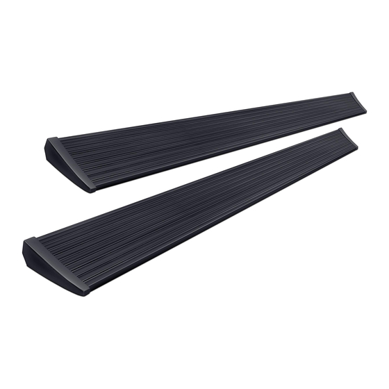
- Page 2 PARTS LIST AND HARDWARE IDENTIFICATION 19-03199-11 End cap left (x1) 19-03199-12 End cap right (x1) 18-02663-90 T-nut insert (x2) 19-03236-90 Socket cap screw (x2) 19-03237-90 Nut plate (x2) 20-03318-48 Step assembly 10-03606-20 Driver (2 door) 10-03610-20 (2 door) 10-03606-21 Passenger (2 door) Idler Linkage Motor Linkage 19-03717-90L...
- Page 3 PARTS LIST AND HARDWARE IDENTIFICATION 16-02634-90 19-02740-90 16-03014-90 19-03467-90 19-02802-90 Button Head Bolt Hex Flange Bolt Washer Black U nut Socket Cap 19-03354-90 Posi-Taps™ (Red/Grey) 19-03302-90 LED Lamp 19-03352 -90 19-02805-90 19-02721-90 Flat Head 19-03339-90 Cable Tie 6” Cinch Fastener Cap Screw Cable Tie 11”...
- Page 4 Slide motor assembly onto drive shaft and mounting bosses of driving linkage assembly. Use flathead socket head cap screws (16) on the inner location. Next use hex bolt (23) and washer (22) on outer location and tighten to 8 ft-lbs / 11Nm. Motor faces to front of vehicle Driver side Passenger side...
- Page 5 Fasten loosely to allow for adjustments. Remove fuse from Power Step wire harness. Tighten 4 socket cap screws with 3/16” allen wrench. Torque to 10 ft-lbs. (13.5 N-m) Install controller on passenger side at firewall.
- Page 6 Posi-Tap™ instructions Use Posi-Tap connectors to connect Power Step trigger wires to like colored wires in the factory system as shown: Violet/White wire in loom coming from front door, Violet/ Yellow and Violet/Grey are not used tape off ends.
- Page 7 Repeat linkage installation on driver side Insert plastic push pin rivets in mounting holes of Insert plug from wire harness onto motor. Slide motor cover. Use pliers to ease installation. rubber grommet on wire harness into slot of motor cover. Insert motor cover onto motor. Slide motor assembly onto drive shaft and mounting bosses of driving linkage assembly.
-
Page 8: Final System Check
Check that all doors activate the Power Step and the LED Lights work when doors open and close. Reinstall any remaining trim panels. FINAL SYSTEM CHECK Check that all doors activate the PowerStep and the LED lights work when doors open and close. -
Page 9: Year Limited Warranty
5-YEAR LIMITED WARRANTY AMP RESEARCH warrants this product to be free from defects in material and workmanship for FIVE (5) YEARS FROM DATE OF PURCHASE, provided there has been normal use and proper maintenance. This warranty applies to the original purchaser only.
Need help?
Do you have a question about the Power Step and is the answer not in the manual?
Questions and answers