Advertisement
Quick Links
APPLICATION
Jeep Gladiator JT
(For Gas, Diesel and 4XE models)
REALTRUCK TECH SUPPORT 1-888-983-2204 (Press 2) Monday - Friday, 8:00 AM - 5:00 PM EST
Designed and manufactured by RealTruck AMP Research
Patent Protected. Please see our product site for applicable patents. www.realtruck.com/b/amp-research/
© RealTruck Group, Inc., 2024 • Three-year limited warranty. • Professional installation is recommended.
www.realtruck.com
2020 - 2024
I N S T A L L A T I O N G U I D E
• Made in Mexico
®
1/15
AMP Part #
75135-01A
INSTALLATION TIME
3-5 Hours
Professional installation recommended
SKILL LEVEL
1 2 3
4= Experienced
TOOLS REQUIRED
q Safety goggles
q Measuring tape
q 10 mm socket
q 13 mm socket
q 1/2" socket
q Ratchet wrench and extension
q Wire crimpers
q Wire stripper / cutter
3 /16" hex key wrench (allen wrench)
q
q
4mm hex key wrench ( allen wrench )
q
Electrical tape
q
Weather proof caulking (silicone sealer)
q
Silicone spray
q Drill
q Drill bit 3/16"
q Fish tape or stiff piece of wire
WARRANTY
5-Year Limited Warranty
IM75135 rev 06.11.24
4
Advertisement

Related Manuals for AMP Research REALTRUCK Power Step 75135-01A


Summary of Contents for AMP Research REALTRUCK Power Step 75135-01A
- Page 1 WARRANTY 5-Year Limited Warranty REALTRUCK TECH SUPPORT 1-888-983-2204 (Press 2) Monday - Friday, 8:00 AM - 5:00 PM EST Designed and manufactured by RealTruck AMP Research • Made in Mexico ® Patent Protected. Please see our product site for applicable patents. www.realtruck.com/b/amp-research/ ©...
- Page 2 I N S T A L L A T I O N G U I D E EXPLODED VIEW • Motor • Hex Head Bolt CAUTION: HANDLE WITH CARE. To ensure our customers receive all components with full integrity, we pack the motors separate from their linkage assemblies.
- Page 3 PARTS LIST AND HARDWARE IDENTIFICATION End cap left (x1) End cap right (x1) T-nut insert (x2) Socket cap screw (x2) Nut plate (x2) Step assembly Motor Linkage Butt Connector Motor Linkage Wire harness assembly Passenger assembly Driver OBD Module Posi-Lock® OBD Module extension LED Light Bracket Controller XTA...
- Page 4 PARTS LIST AND HARDWARE IDENTIFICATION Washer M8 Hex Bolt w Socket Cap M8 Button Screw Conical washer Head Bolt Shim Spacer Cable tie (7”) Cable tie (11”) Motor Cover CRH Motor Cinch Fastener M8 Head Hex Bolt www.realtruck.com 4/15 IM75135 rev 06.11.24...
- Page 5 J E E P G L A D I A T O R J T Mounting positions circled for front and rear linkage mounting points. Driver side shown. Note: Motors face forward on each side. Driver side shown. Rear linkage Front linkage mounting location mounting location...
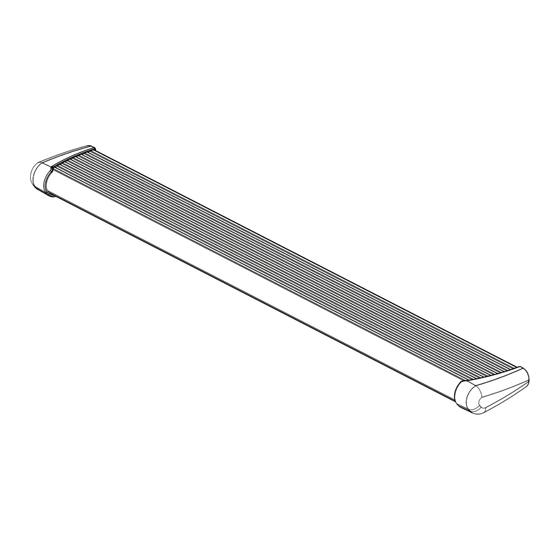
- Page 6 J E E P G L A D I A T O R J T Mount step extrusion (1) to linkage assemblies. Line up T-nuts in step assembly with slots in lower mounts of linkage assemblies. Fasten loosely to allow for adjustments. Line up step extrusion with rear fender well.
- Page 7 J E E P G L A D I A T O R J T Gas Models ONLY, follow steps 6 and 7 then go to step 12. GAS MODELS ONLY: Remove fuse from Power Step Wire Harness. Prepare large tie-wraps (18) for mounting Power Step Controller (9).
- Page 8 J E E P G L A D I A T O R J T Diesel models ONLY, follow steps 8 and 9 then go to step 12. DIESEL MODELS ONLY: Remove fuse from Power Step Wire Harness. Prepare large tie-wraps(18) for mounting Power Step Controller (9).
- Page 9 J E E P G L A D I A T O R J T 4XE Models ONLY, follow steps 10 and 11 then proceed to step 12. 4XE MODELS ONLY: Remove fuse from Power Step Wire Harness. Prepare large tie-wraps (18) for mounting Power Step Controller (9).
- Page 10 J E E P G L A D I A T O R J T Press and release glove box safety tab to fully open and remove glove box, next, release glox box dampener located on the left side. Glove box safety tab 1 12 Carefully leave glove box hanging to expose plugs behind it.
- Page 11 J E E P G L A D I A T O R J T Pull back carpet on passenger side on the top side of middle console and hen use a hard piece of wire or fish tape to route OBD II Extension (7) behind middle console. Tape open end of extension to the tube and push the tube through middle console.
- Page 12 J E E P G L A D I A T O R J T Route trigger wires through firewall. Locate round plastic plug on firewall to the left of the brake assembly. Drill small hole using a 3/16 drill bit. Route trigger wires (4) through firewall. Use supplied posi-lock®...
- Page 13 J E E P G L A D I A T O R J T OBD II install: Use Supplied Posi-Lock® connectors to attach the Plug and Play Module to the Harness. Attach matching colors on the harness to the wires on the module. Plug in module to OBD II port on the vehicle.
- Page 14 J E E P G L A D I A T O R J T On driver side, run Wire Harness leg down and along underside of the vehicle floor and frame to front Drive Linkage. Connect harness to motor and secure harness with tie wraps. Route remainder of wire harness towards rear linkage assembly for LED lights.
- Page 15 J E E P G L A D I A T O R J T Check that all doors activate the Power Step and the LED Lights work when doors open and close. Reinstall any remaining trim panels. FINAL SYSTEM CHECK Check that all doors activate the PowerStep and the LED lights work when doors open and close.
- Page 16 AMERICAN DESIGNED & ENGINEERED Thank you for your recent RealTruck purchase. REGISTER YOUR PRODUCT TODAY FOR FASTER SERVICE & PRODUCT UPDATES Please visit: https://realtruck.com/warranty-registration/ or scan the QR Code Product Registration Benefits: • Ensure we have your purchase receipt and product info in our system which is required for warranty.
- Page 17 Caution! Keep hands away when the running board is in motion. 5-YEAR LIMITED WARRANTY RealTruck / AMP RESEARCH warrants this product to be free from defects in material and workmanship for FIVE (5) YEARS FROM DATE OF PURCHASE, provided there has been normal use and proper maintenance. This warranty applies to the original purchaser only.
Need help?
Do you have a question about the REALTRUCK Power Step 75135-01A and is the answer not in the manual?
Questions and answers