Table of Contents
Advertisement
Quick Links
Advertisement
Table of Contents

Related Manuals for COBHAM EXPLORER 5075GX


Summary of Contents for COBHAM EXPLORER 5075GX
- Page 1 EXPLORER 5075GX Auto-Deploy Antenna System Installation and user manual...
- Page 3 EXPLORER 5075GX Installation and user manual Document number: 98-143492-B Release date: 7 November 2014...
- Page 4 In the event of any discrepancies, the English version shall be the governing text. Thrane & Thrane A/S is trading as Cobham SATCOM. Copyright ©...
- Page 5 Cobham SATCOM may perform service - failure to comply with this rule will void the warranty. Power supply The voltage range for the EXPLORER 5075GX is 100 – 240 VAC (nominal), 4 A, 50/60 Hz. WARNING! Before disassembling or performing any maintenance or upgrades, unplug the unit from power source.
- Page 6 As per FCC §15.105: Information to the User NOTE: This equipment has been tested and found to comply with the limits for a Class B digital device, pursuant to part 15 of the FCC Rules. These limits are designed to provide reasonable protection against harmful interference in a residential installation.
-
Page 7: Table Of Contents
Assembly & start up What’s in the box ......................3-1 3.1.1 To unpack ..........................3-1 3.1.2 Initial inspection ........................3-2 To assemble the EXPLORER 5075GX ..............3-2 3.2.1 Prerequisites .......................... 3-2 3.2.2 Assembly ..........................3-3 Start up with auto-acquisition ................3-6 To stow the antenna ..................... - Page 8 5.2.2 Software update procedure ................... 5-9 Status signalling with LEDs and status messages ........ 5-12 5.3.1 LEDs on the keypad of the EXPLORER 5075GX ..........5-12 5.3.2 Status information of the modem ................5-13 To return units for repair ..................5-14...
-
Page 9: About This Manual
1.1.1 Intended readers This is an installation and service manual for the EXPLORER 5075GX system, intended for users of the system and service personnel. Personnel installing or servicing the system must be properly trained and authorized by Cobham SATCOM. It is important that you observe all safety requirements listed in the beginning of this manual, and install the system according to the guidelines in this manual. -
Page 10: Precautions
Some materials can be dangerous. CAUTION! Do not use materials that are not equivalent to materials specified by Cobham SATCOM. Materials that are not equivalent can cause damage to the equipment. Chapter 1: About this manual... -
Page 11: Chapter 2 Introduction
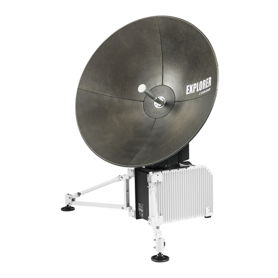
2.1.1 Overview The EXPLORER 5075GX is an auto-deploy 75 cm fly-away antenna system, designed for operation in the Ka-band. The integrated GX modem, also known as the iDirect Core Module, commands the system to automatically acquire an operational satellite within five minutes based on the terminal's GPS location. -
Page 12: Global Express Service
The following figure shows the coverage map of the GX service at global service introduction. Figure 2-2: GX coverage map 2.1.3 Service activation Before you can start using the EXPLORER 5075GX, you need to activate the system for the GX service. Contact your service provider for activation. Chapter 2: Introduction 98-143492-B... -
Page 13: Description Of The System Components
Description of the system components Description of the system components 2.2.1 Antenna positioner The auto-deploy antenna positioner can accommodate 4° to 83° of angular movement in the elevation axis and ± 90° in the azimuth axis. The mechanical assemblies rely on two independent axes to allow for precise antenna pointing. -
Page 14: Electronics Enclosure And Support Legs
Description of the system components has been designed to meet wind load and thermal distortion requirements; see Technical specifications on page A-1 for more detail. Figure 2-4: Center hub with four latches for the 4 panels 2.2.4 Electronics enclosure and support legs The modem, Antenna Control Unit (ACU), and AC Power Supply are packaged in the IP65 electronics enclosure. -
Page 15: Keypad And Display
The display has a two line menu system. The display also supports two status lines (Upper and Lower) for compact satellite and antenna information. For a description of the LED light indicators see LEDs on the keypad of the EXPLORER 5075GX on page 5-12. 2.2.6 Web interface for setup and troubleshooting To fully configure the EXPLORER 5075GX, use the built-in web interface. -
Page 16: Lan Ports And Wlan
• Three connectors (LAN 2 to LAN 4) for user ports for Internet etc., configured by the GX modem. The EXPLORER 5075GX has a WLAN module. Access to one of the LAN ports using WLAN must be set up in the web interface, see To configure the LAN network on page 4-6. -
Page 17: Assembly & Start Up
What’s in the box 3.1.1 To unpack The EXPLORER 5075GX antenna system is packaged into two transit cases. • Case 1 - RF assembly and reflector • Case 2 - Electronics enclosure and antenna positioner Figure 3-1: 2 transit cases Take care when handling the feed assembly. -
Page 18: Initial Inspection
The recommended weight values to hold the terminal to the ground can be provided upon request. • Place the EXPLORER 5075GX in North-South orientation for best performance during acquisition. • Pay attention not to cover the GNSS (GPS, Glonass, etc.) module. -
Page 19: Assembly
In the EXPLORER 5075GX auto-deploy terminal, access points have been provided to access the azimuth and elevation drives. At higher wind speeds, the antenna can be manually driven to the stow position using the manual drive tool included in the transport cases. - Page 20 To assemble the EXPLORER 5075GX To assemble the EXPLORER 5075GX, do as follows: 1. Unpack the electronics enclosure and place the electronics enclosure upon level ground and deploy the two support legs. Figure 3-3: Electronics enclosure and support legs The two support legs and support feet provide additional stability and prevent movement of the system.
- Page 21 To assemble the EXPLORER 5075GX Figure 3-5: To mount the antenna positioner 7. Re-engage the thumbscrews to lock the brackets into place. 8. Unpack the four interchangeable panels. 9. Release the four locking mechanisms on the reflector hub, insert the two bottom panels and re-secure the locking mechanism on the reflector hub.
-
Page 22: Start Up With Auto-Acquisition
Start up with auto-acquisition Figure 3-8: Tx, Rx RF and BUC cables 13.Connect the AC Power Adaptor to the electronics enclosure. Figure 3-9: AC power connection 14.Use the four RJ-45 ports for making IP-data connections; there are two separate functions accessible using these ports: LAN1 (leftmost) for access to the web interface (setup and troubleshooting) LAN2 to LAN4 for Internet use etc. -
Page 23: To Stow The Antenna
4. Proceed to maximum value on the satellite signal and achieve LOCK status. The modem then enters the network and begins passing user traffic. This pointing algorithm uses Cobham's proven TracStar technology that is currently deployed in thousands of terminals around the world. -
Page 24: To Disassemble And Pack The Antenna
To disassemble and pack the antenna To stow the antenna using the web interface 1. Connect a PC to the LAN1 connector. 2. Open an Internet browser and type the default IP address: http://192.168.0.1. When the login screen is displayed you have verified that the connection can be established. -
Page 25: Setup And Operation
4.1.1 Introduction Use the built-in web interface of the EXPLORER 5075GX to set up the antenna, i.e. setup of the WLAN and for service and troubleshooting. You can use a standard Internet browser. A satellite profile with the GX Modem is already set up at the factory. No further profiles are needed. - Page 26 Setup using the web interface When the login screen is displayed you have verified that the connection to the EXPLORER 5075GX can be established. The web interface is ready for use. You can continue to configure the system. Figure 4-1: Logon screen If you cannot establish a connection there might be problems with the Proxy server settings of your PC.
- Page 27 Setup using the web interface Topics in the web interface Use the site map to get an overview over the existing menus and submenus. You can click on each menu in the site map to go directly to the page or display the respective submenu. Figure 4-3: Topics in the web interface (SITE MAP) The DASHBOARD is the first screen that is displayed when the user or administrator enters the IP address of the web interface.
- Page 28 Setup using the web interface The web interface consists of the following sections: Figure 4-4: Web interface: DASHBOARD 1. The navigation pane holds the main menu. Clicking an item in the menu opens a submenu in the navigation pane or a new page in the contents section. 2.
- Page 29 4-14. To connect a PC To connect a PC to the EXPLORER 5075GX do as follows: 1. Connect a PC to LAN1 port (Service port, standard Ethernet, leftmost). You can configure it according to your network requirements. See To configure the LAN network on page 4-6 for more information.
-
Page 30: To Configure The Lan Network
Important the Internet. It must be located behind a dedicated network security device such as a firewall. If any ports of the EXPLORER 5075GX are exposed to the Internet you must change the default passwords as anyone with access and malicious intent can render the EXPLORER 5075GX inoperable. - Page 31 Make the necessary changes on this page and click Apply. Sections Preferred use NETWORK Host The host name is used for identifying the EXPLORER 5075GX. The name default host name is acu. You can change the name. Letters (a-z), digits (0-9) and hyphen (-) are allowed as legal characters.
- Page 32 Setup using the web interface Sections Preferred use LAN Port 2, 3 User data ports, configured automatically by the modem. The VLAN and 4 table shows this configuration. LAN Port 5 No connector, only internal connection.This network is connected to the modem (iDirect GX Modem).
-
Page 33: Wlan Settings
Disabled: WLAN access point is hidden. 6. Type in the SSID of your choice or accept the default SSID, which is Cobham. The SSID is the name of the wireless local area network. It is a text with maximum 32 characters. -
Page 34: To Deploy, Stow, Stop Or Jog The Antenna
Setup using the web interface 4.1.5 To deploy, stow, stop or jog the antenna On this page you can deploy, stow or stop the antenna. • Deploy: Prepare the antenna for pointing after it has been stowed, stopped or jogged. •... -
Page 35: Navigation
Manual - enter values from other position source. (Accuracy should be better than 50 m.) Compass mode Automatic - magnetic heading is used (default). Manual - enter a value for the direction of the EXPLORER 5075GX as an alternative to the magnetic heading (0 to 360 degrees, precision ±20°). -
Page 36: Administration
Setup using the web interface 4.1.7 Administration In this section of the web interface you can configure the following administrative settings: • To access the administration settings (user name, password) • To set up user permissions (guest login) • To import and export a system configuration •... - Page 37 Setup using the web interface To change the administrator password, do as follows: 1. After entering the administrator user name and password in the ADMINISTRATION page, locate the section Change administrator logon. Figure 4-10: Web interface: Administration, change administrator logon and password 2.
-
Page 38: To Set Up User Permissions (Guest Login)
4.1.8 To set up user permissions (guest login) You can manage user access to certain functions of the EXPLORER 5075GX system. You can allow or deny users that are not administrators (user name: guest, password: guest) access to certain functions and make these pages read-only. This is useful if you want to protect the system against unintended changes or tampering of the system. -
Page 39: To Import And Export A System Configuration
4.1.9 To import and export a system configuration If you need to reuse a configuration in another EXPLORER 5075GX, you can save the current configuration to a file, which can then be loaded into another EXPLORER 5075GX. You can also use this feature for backup purposes. -
Page 40: To Reset To Factory Default
Setup using the web interface 4.1.10 To reset to factory default When resetting EXPLORER 5075GX to factory default, the following settings are deleted or reset to factory default: • All added satellite profiles • All added VSAT modem profiles • Changes in the network setup •... - Page 41 Setup using the web interface Reset to factory default - integrated GX modem CAUTION! Administrators only. Close this page for guest users, see To set up user permissions (guest login) on page 4-14. To reset the integrated modem to factory default, do as follows: 1.
-
Page 42: Keypad And Display Menus
7;:0$5 Signal strength Figure 4-16: Display and keypad of the ACU (example) 1. Current status of the EXPLORER 5075GX (examples): ANTENNA SOFTWARE UPLOAD ANTENNA POST (Power-On Self Test) READY (waiting for data from the modem or no satellite profile selected) -
Page 43: Navigating The Menus
Keypad and display menus After 1 hour the display is dimmed to lowest intensity. Press any key to light up the display. 4.2.2 Navigating the menus Use the keypad to navigate the menus. • Press OK or to select a menu item. •... - Page 44 Keypad and display menus Top-level menu Top-level Description menu MAIN View with current status of the EXPLORER 5075GX. Example when logged on to the satellite: 0DLQ 1$9:*+ 0'0: 1(72. /$1: 1 ± 3 4 $&48,6,7,21 2. 6$7: 151,2 : 5;:1-/ + 19,707/18,25 7;:0$5...
- Page 45 Keypad and display menus ANTENNA Description VERSIONS Current software version. SERIAL NUMBERS Serial number of the EXPLORER 5075GX Table 4-7: ANTENNA menu (Continued) MODEM Description MODEM TYPE Current modem type. TX ENABLE On or off, information delivered by the connected GX modem.
-
Page 46: Brightness Of The Display
Keypad and display menus EVENT Description In this menu all active events are listed. Use and to go through the <EVENT> active events. Events can be of the type WARNING or ERROR. If a new event occurs or there is a change in the event list while you are in the EVENTS menu, a * is shown in the upper left corner of the display, next to the menu name. -
Page 47: Service
5.1.1 Preventative maintenance The EXPLORER 5075GX is constructed to require a minimum amount of regular maintenance. The following checks should be undertaken on a regular basis: • Inspect the reflector front surface for physical damage including chips and cracks. Any substantial damage can affect antenna performance and may require a portion of the reflector to be replaced. -
Page 48: Help Desk And Diagnostics Report
2. Click the link, enter support contact information and click Apply. At Legal notice the licence text for the source code of the parts of the EXPLORER 5075GX software that fall under free and open source software can be displayed. -
Page 49: To Point With The Hand Crank
For a list of all events with description, error code (ID), explanation and remedy see System messages on page B-1. Self test You can start a self test of the EXPLORER 5075GX ADU and ACU. 1. Click Self test in the HELPDESK page. Self test 2. -
Page 50: Reset
- integrated GX modem on page 4-17. Reset to factory defaults using the web interface You can reset the EXPLORER 5075GX to factory defaults. See To reset to factory default on page 4-16. Warning! Reset to factory default will delete all settings, including... -
Page 51: Satellite Profiles And Vsat Modem Profiles
General support You can reset the GX modem to factory defaults. See Reset to factory default - integrated GX modem on page 4-17. 5.1.5 Satellite profiles and VSAT modem profiles Satellite profiles A satellite profile with the GX Modem is already setup at the factory. You may add a satellite profile with the generic modem for troubleshooting purposes. - Page 52 General support • FCC (FCC §25.205): 5 degrees 5. Click Apply to save the settings for the satellite profile. VSAT modem profiles On the page VSAT modem profiles you create, edit or delete VSAT modem profiles. The VSAT modem profile GX Modem is already set up at the factory. It is useful for troubleshooting to create a VSAT modem profile with the Generic modem.
-
Page 53: Gx Modem: One Touch Commissioning
General support 5.1.6 GX Modem: One Touch Commissioning In some cases you may have to make the One Touch Commissioning for the modem. WARNING! For your safety: Active RF transmission may occur during an OTC procedure. Software updates may also occur, yet the system is in receive- only mode during such auto-updates. -
Page 54: Proxy Server Settings In Your Browser
General support 5.1.7 Proxy server settings in your browser If you are connecting your computer using a LAN or WLAN interface, the Proxy server settings in your browser must be disabled before accessing the web interface. Most browsers support disabling of the Proxy server settings for one specific IP address, so you can disable Proxy server settings for the web interface only, if you wish. -
Page 55: Software Update
See To configure the LAN network on page 4- 6 for more information. 3. Open your Internet browser and enter the IP address of the EXPLORER 5075GX. The default IP address is http://192.168.1.2. 4. Type in the user name admin and the password 1234 to access the Dashboard. - Page 56 To verify the software update 1. The software version can be viewed in the DASHBOARD window of the web interface. 2. After completing the software update procedure, the EXPLORER 5075GX will perform a POST (Power On Self Test). 3. When the POST has finished, the green Pass/Fail LED on the keypad must become steadily green.
- Page 57 Software update 4. Verify that the software update has been completed successfully. You find the software version number in the DASHBOARD window of the web interface. Figure 5-11: Verifying software update, SAILOR 900 VSAT Software update (modem) The modem detects automatically whether a software upgrade is needed. If yes, software upgrade is done automatically via the satellite link.
-
Page 58: Status Signalling With Leds And Status Messages
Status signalling with LEDs and status messages Built-In Test Equipment The EXPLORER 5075GX has a Built-In Test Equipment (BITE) function in order to make fault diagnostics easy during service and installation. The BITE test is performed during: • Power On Self Test (POST), which is automatically performed each time the system is powered on. -
Page 59: Status Information Of The Modem
5.3.2 Status information of the modem The modem status is shown in the display of the EXPLORER 5075GX in the menu Modem and also in short form in the upper status line. The current status is communicated by a text string: Steady green, red or yellow, or flashing green, red or yellow. -
Page 60: To Return Units For Repair
Cobham SATCOM Self Service Center web-portal, which may help you solve the problem. Your dealer, installer or Cobham SATCOM partner will assist you whether the need is user training, technical support, arranging on-site repair or sending the product for repair. -
Page 61: Appendix A Technical Specifications
Appendix A Technical specifications This appendix has the following sections: • Antenna characteristics • Product Dimensions Antenna characteristics Ka-Band Receive Transmit Feed 2 Port Circular Frequency Range (GHz) 19.2 - 20.2 29 - 30 Gain (dBi ± 0.2) 41.0 44.5 ... - Page 62 Antenna characteristics Power requirement 100-240VAC, 4A, 50/60Hz 150W (max) Weights and measures Terminal 28.6 kg (63 lbs) Transport inside 2 cases <31.7 kg (<70 lbs) per case, Airline checkable Environmental characteristics Wind Speed - Operational 48 km/h (30 mph) gusts up to 72 km/h (45 mph) (anchored) Temperature - Operational -25°...
-
Page 63: Product Dimensions
Product Dimensions Product Dimensions The dimensions shown below reflect the space needed to accommodate the full range of motion in elevation and azimuth. A.2.1 Side view Figure A-1: EXPLORER 5075GX side view 98-143492-B Appendix A: Technical specifications... -
Page 64: Top View
Product Dimensions A.2.2 Top view Figure A-2: EXPLORER 5075GX top view Appendix A: Technical specifications 98-143492-B... -
Page 65: Rear View
Product Dimensions A.2.3 Rear view Figure A-3: EXPLORER 5075GX rear view 98-143492-B Appendix A: Technical specifications... - Page 66 Product Dimensions Appendix A: Technical specifications 98-143492-B...
-
Page 67: Appendix B System Messages
• CM (Continuous Monitoring) – automatically performed while the system is in operation. When the EXPLORER 5075GX detects an event that requires your action, it issues an event message and the red Fail/Pass LED in the LED panel of the ACU is lit. As long as an event is active, it is shown in the ACU displayControl Panel the web interface (in HELPDESK >... -
Page 68: List Of Events
List of events List of events Error Severity Description Explanation code (ID) 08065-0 WARNING GNSS data Missing GPS data (fix). 08067-0 ERROR PCB temperature ADM temperature too high. The ACU is not equipped with a fan, so make sure there is compliance with the environmental specifications. - Page 69 List of events Error Severity Description Explanation code (ID) 08844-0 WARNING BUC voltage The BUC voltage is out of range. 08845-0 WARNING LNB voltage The LNB voltage is out of range. The LNB might be switched off to protect the power supply circuitry. Reactivate satellite profile to try again, check LNB cable and surroundings if the problem persists.
- Page 70 List of events Event ID Severity Description Explanation 0C001 Error Compass/dish Not seeing the compass 0C002 Error GNSS position/velocity Not detecting any GPS satellite 0C003 Error Base angle level Antenna base angle exceeds 8°. Level the antenna 0C005 Error AZ major over travel Antenna has been driven beyond the azimuth electrical limit 0C006...
- Page 71 ADU Bus Slave ACU Digital Module. A main processor board in the ACU. Antenna Module Bus Block Up Converter. The BUC can be thought of the “transmitter”, and its actions are effectively the direct opposite to the LNB. The BUC consists of the Up Converter and HPA. Continuous Monitoring Digital Video Broadcasting, a set of standards relating to digital television.
- Page 72 Index Internet Protocol. The method or protocol by which data is sent from one computer to another on the Internet. Keyboard and Display Module of the ACU Local Area Network Light Emitting Diode Low Noise Block. A device used to amplify or boost the weak received signal without amplifying the noise signals (hence the “low noise”...
-
Page 73: 301 489-1 V1.9.2 (2011-09
calibration , 5-5 satellite data access , 4-16 calibration data , 4-14 limit , 4-16 reset acquisition center hub , 4-2 search pattern , 3-5 panels activation , 4-13 change administrator password , 2-2 service , 4-14 change network setting ACU display configuration , 4-18... -
Page 74: Index
Index errors , B-4 antenna , 4-14 , B-1, B-2 events , 4-10 web interface , B-4 antenna , 5-3 list of active , 4-15 export configuration keypad , 2-5 description factory default , 4-16 calibration data , 4-16 reset factory defaults , 5-4, 5-5 reset to... - Page 75 Index Index security key , 4-9 wireless network , 5-7 One Touch Commissioning , 5-3 self test , 3-2 orientation , 2-2 service activation service port , 4-1 IP address setup , 4-14 user permissions panels , 4-3 site map , 3-5 attach to center hub , 5-9...
- Page 76 , 4-8 VLAN port membership table , B-1 warning messages , 5-3, B-2 warnings , B-4 antenna , 5-14 warranty web interface , 5-7 browser settings , 4-1 connect , 3-6 connection , 5-7 core module , 4-2 login , 4-5 navigating , 2-5 overview...
- Page 77 Index Index-4 98-143492-B...
- Page 78 98-143492-B www.cobham.com/satcom...
Need help?
Do you have a question about the EXPLORER 5075GX and is the answer not in the manual?
Questions and answers