Table of Contents
Advertisement
Quick Links
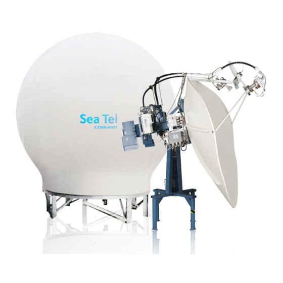
Sea Tel 9711IMA-70
Installation Manual
This technical data is subject to US Government export control in accordance with
the Export Administration Regulations. Export of this data to any foreign country
or disclosure of this data to a Non-US person may be a violation of Federal law.
Sea Tel, Inc.
(trading as Cobham SATCOM)
4030 Nelson Avenue
Concord, CA 94520
Tel: +1 (925) 798-7979
Fax: +1 (925) 798-7986
Web:
http://www.cobham.com/satcom
February 11, 2016
EAR Controlled - ECCN EAR99
EAR Controlled - ECCN EAR99
Thrane and Thrane A/S
(trading as Cobham SATCOM)
Lundtoftegaardsvej 93 D, 2800 Kgs.
Lyngby, Denmark
Tel: +45 3955 8800
Fax: +45 3955 8888
Email:
satcom.ohc@cobham.com
Document No. 99-150146-A
Advertisement
Table of Contents

Related Manuals for COBHAM SEA TEL 9711IMA-70


Summary of Contents for COBHAM SEA TEL 9711IMA-70
- Page 1 Sea Tel 9711IMA-70 Installation Manual EAR Controlled - ECCN EAR99 This technical data is subject to US Government export control in accordance with the Export Administration Regulations. Export of this data to any foreign country or disclosure of this data to a Non-US person may be a violation of Federal law.
- Page 2 The information contained in this document is proprietary to Sea Tel, Inc. This document may not be reproduced or distributed in any form, without prior written consent of Sea Tel, Inc. The information in this document is subject to change without notice. Sea Tel Inc. is also doing business as Cobham SATCOM. EAR Controlled - ECCN EAR99...
- Page 3 9711IMA-70 Revision History ECO# Date Description February 11, 2016 Production Release EAR Controlled - ECCN EAR99...
- Page 4 Sea Tel Inc. 4030 Nelson Ave., Concord California, 94520, USA T: +1 (925) 798-7979 F: +1 (925) 798-7986 R&TTE Declaration of Conformity Sea Tel Inc. declares under our sole responsibility that the products identified below are in conformity with the requirements of: DIRECTIVE 1999/5/EC of the European Parliament and of the Council of 9 March 1999 on Radio equipment and Telecommunication Terminal Equipment and the mutual recognition of their conformity.
- Page 5 25.221 (a)(1)(iii). Sea Tel maintains all relevant test data, which is available upon request, to verify these declarations. 4/16/2013 Peter Blaney, Chief Engineer Date Cobham – SATCOM Sea Tel Products. EAR Controlled - ECCN EAR99 Document Number 130449 Revision F...
- Page 6 9711IMA-70 This Page Intentionally Left Blank EAR Controlled - ECCN EAR99...
-
Page 7: Table Of Contents
Table of Contents 9711IMA-70 1. INTRODUCTION ......................................1-1 1.1.................................. 1-1 ENERAL YSTEM ESCRIPTION 1.2........................................... 1-1 URPOSE 1.3................................... 1-1 THER NPUTS TO THE YSTEM 1.4....................................1-1 YSTEM OMPONENTS 1.5................................1-2 NTENNA ONFIGURATION 1.6..................................1-2 ETWORK RBITRATOR 1.7. - Page 8 9711IMA-70 Table of Contents 3.9. ADE ....................................3-24 NSTALLING 3.9.1. Hoist the ADE ................................... 3-24 3.9.2. Connecting the ADE ................................3-24 3.9.3. Remove stow Straps ................................3-25 3.9.4. ADE Final Checks ................................... 3-25 3.10. I ............................3-25 NSTALLING THE ELOW ECKS QUIPMENT 3.10.1.
- Page 9 Table of Contents 9711IMA-70 14.1. T ........................14-1 ROUBLESHOOTING HIPS OMPASS PROBLEMS 14.1.1. STEP-BY-STEP ................................... 14-1 14.1.2. 1:1 SYNCHRO .................................... 14-1 14.1.3. 360:1 Synchro ................................... 14-2 15. MAINTENANCE ......................................15-1 15.1. W ..................................15-1 ARRANTY NFORMATION 15.2. T ..............................15-1 ORQUE AND OCTITE PECIFICATIONS...
- Page 10 9711IMA-70 Table of Contents This Page Intentionally Left Blank EAR Controlled - ECCN EAR99...
-
Page 11: Introduction
9711IMA-70 Introduction Introduction WARNING: RF Radiation Hazard - This stabilized antenna system is designed to be used with transmit/receive equipment manufactured by others. Refer to the documentation supplied by the manufacturer which will describe potential hazards, including exposure to RF radiation, associated with the improper use of the transmit/receive equipment. -
Page 12: Dual Antenna Configuration
Introduction 9711IMA-70 Figure 1 -1 Series 11 TXRX Simplified Block Diagram 1.5. Dual Antenna Configuration Sometimes, due to very large blockage conditions, you may need to install a dual antenna configuration to provide uninterrupted services. Two full antenna systems are installed and the MXP control outputs are connected to an arbitrator switch panel which then is connected to the below decks equipment. -
Page 13: Automatic Beam Switching (Abs)
9711IMA-70 Introduction Demand for greater bandwidth throughputs has led to service offerings that include access to multiple networks from the vessel. To facilitate this a dual network (two modems) configuration is required. This can be a single antenna – dual network configuration which allows the ship to access either of two networks. One antenna system is installed and its’... - Page 14 Introduction 9711IMA-70 This Page Intentionally Left Blank EAR Controlled - ECCN EAR99...
-
Page 15: Site Survey
9711IMA-70 Site Survey Site Survey There are three objective of the site survey. The first is to find the best place to mount the antenna and the BDE. The second is to identify the length and routing of the cables and any other items or materials that are required to install the system. -
Page 16: Mounting Foundation
Site Survey 9711IMA-70 2.3. Mounting Foundation 2.3.1. Mounting on Deck or Deckhouse While mounting the ADE on a mast is a common solution to elevate the ADE far enough above the various obstructions, sometimes the best mounting position is on a deck or deckhouse top. These installations are inherently stiffer than a mast installation as the design of the deck/deckhouse structure is prescribed by the ship’s classification society. -
Page 17: Mast Configurations
9711IMA-70 Site Survey two accelerations – tangential and radial. These accelerations vary in a periodic function, out-of-phase from the ship response to the wave motions. Radial acceleration is the acceleration acting on the mass of the ADE pulling away from the center of the axis (roll or pitch). -
Page 18: Vertical Masts
Site Survey 9711IMA-70 2.5.1. Vertical Masts Vertical masts are a very ancient and common mast design. In essence, it is the mast derived from the sailing mast and adapted for mounting the ever-increasing array of antennae which ships need to communicate with the world. -
Page 19: Truss Mast
9711IMA-70 Site Survey 2.5.4. Truss Mast Truss masts are a variant on the girder mast concept. Rather than a pair of columns supporting a girder beam, the construction is a framework of tubular members supporting a platform on which the antennae and other equipment are mounted. A typical truss mast is shown in this photograph. -
Page 20: Ade/Bde Coaxial Cables
Site Survey 9711IMA-70 2.8.1. ADE/BDE Coaxial Cables The first concern with the coaxial cables installed between the ADE & BDE is length. This length is used to determine the loss of the various possible coax, Heliax or fiber-optic cables that might be used. You should always provide the lowest loss cables to provide the strongest signal level into the satellite modem. -
Page 21: Installation
9711IMA-70 Installation Installation This section contains instructions for unpacking, final assembly and installation of the equipment. It is highly recommended that final assembly and installation of the Antenna system be performed by trained technicians. Read this complete chapter before starting. 3.1. -
Page 22: Opening Your Crates
Installation 9711IMA-70 3.3. Opening your crates CAUTION: To prevent items from being lost or misplaced, do not unpack this crate until you are ready to assemble and install the equipment. 3.3.1. Location of Items inside the Crates The new Packaging Strategy for 9711 systems has reduced the number of crates from 5 or 4 to only 3 crates. -
Page 23: Pedestal Crate
9711IMA-70 Installation Feed Assembly and LNB Box (Contains: Feed Assembly, LNB, Feed Flex Waveguide and Coaxial Cables). Wave Guide Box (ONLY on some systems). Contains the Flex Waveguide and Coaxial Cable. NOTE: Other 9797B Series Antennas may have the Rigid Waveguide(s) located in the Pedestal Crate. -
Page 24: Radome Crate
Installation 9711IMA-70 Pedestal Mounting Spider Marine Air Conditioner (If included) DAC and BDE Box RF Equipment box (some systems have 2 RF Equipment boxes) Cut the bands holding the Balance Weight Box along with the Hardware and Miscellaneous Box. Stage these items in the location where the Pedestal will be assembled. -
Page 25: Unpacking The Base Frame And Reflector Crate
9711IMA-70 Installation 3.4. Unpacking the Base Frame and Reflector Crate The Base Frame and Reflector now share the same crate. The Base Frame is on the lower deck under the Reflector support structure. The Base Frame, Legs, Feet, Supports and Hardware Kit are located on this crate. The Reflector, the Boxes containing the Feed &... - Page 26 Installation 9711IMA-70 Cut the 2 metal bands holding the base frame in place. Remove the base frame, by hand or with a forklift, out from under the reflector support structure. Move the base frame to the location where it will be assembled. Cut the straps that restrain the Base Frame Legs, Braces, Feet and Hardware Kit Box.
- Page 27 9711IMA-70 Installation 16. Install the feed struts (one at a time) to the reflector, aligning the labels on the end of the feed strut to the label on the dish. 17. Remove the feed assembly from its box. If more than one feed is provided with your system only un-package the feed which will be first used after the ADE is completely assembled.
-
Page 28: Unpacking The Pedestal Crate
Installation 9711IMA-70 20. Apply Loctite 242 to, install and tighten the eight screws (see red arrows) through the front of the scalar plate and into the end of the drop-in feed assembly. 21. Keep the assembled reflector/feed assembly mounted on the reflector support structure until you are ready to install it on the Pedestal. - Page 29 9711IMA-70 Installation Cut the bands holding the DAC and BDE Box (pictured in center). Stage this box where the Below Decks Equipment is temporarily located. Cut the bands holding the Air Con Box (if included). Stage this item in the location where the Base Frame will be assembled.
-
Page 30: Unpacking The Radome Crate
Installation 9711IMA-70 12. Remove the 4 bolts securing the base of the pedestal to the crate deck. Note: These 4 bolts are removed by unbolting them fromONLY on the top side of the crate. There is no longer any need to reach under the pallet to hold nuts while the bolt is being removed! 13. -
Page 31: Assembling The Ade
9711IMA-70 Installation Remove the straps that restrain the radome cap. Leave the radome cap on the pallet with the radome panels for use during the radome assembly. Use diagonal cutters, or shears, to cut the bands that restrain the Hardware kit in the crate. -
Page 32: Marine Air Conditioner
Installation 9711IMA-70 Place the radome base frame on temporary support blocks, or jack stands, at least 22 inches high. Loosely assemble the eight legs, eight interior braces and four outer braces from the underside of the radome base frame to the second hole from the top in the bottom end of the legs using the hardware provided. - Page 33 9711IMA-70 Installation NOTE: Unless otherwise indicated, all nuts and bolts should be assembled with Loctite 2760 or its equivalent. On a flat surface, adjoin two panels (one should be the panel with the door in it) and loosely install hardware in all of the holes in the adjoined vertical flanges.
- Page 34 Installation 9711IMA-70 Set the assembled panels on the base frame assembly and align the center of the door to be directly above the AFT marking on the base frame. Loosely install bolts, fender washers and nuts to attach the panels to the base frame using the hardware provided.
-
Page 35: Sub-Assemble The Upper Panels Of The 144" Radome Assembly
9711IMA-70 Installation 10. Repeat caulking, closing and cleaning the vertical flanges until all of the lower panel vertical seams are closed. 11. Remove the tape from the vertical seams. 12. Insert small wedges between the lower radome panes and the base pan. 13. - Page 36 Installation 9711IMA-70 To provide a clean caulked seam all around the panels: apply painters masking tape to the outside perimeter of each of the panels about ¼“ from the top, bottom, left and right edges at each flange joint. The tape will be removed just before the radome caulking has had time to set.
- Page 37 9711IMA-70 Installation 11. (Outside person) Climb onto the upper panel assembly, have someone (third person required only for this step) hand the cap to the person on top of the radome. 12. Insert the cap into the top of the radome with a twisting rotation.
-
Page 38: Sub-Assemble The Antenna Pedestal
Installation 9711IMA-70 3.7.6. Sub-assemble the Antenna Pedestal Refer to the General Assembly drawing for your system and the procedure below. Install the Base Stand, or Mounting Spider, onto the Base Pan using the hardware provided. Apply Loctite to and tighten the mounting bolts. - Page 39 9711IMA-70 Installation Mount the C-Band RF Equipment on the left side of the pedestal, assuring the waveguide port is facing up (foreground of this view). Waveguide port Connect AC Power cable. Connect RF Input. cable. 10. Connect M&C cable. Using a small flat blade screwdriver, tighten the retaining screws.
- Page 40 Installation 9711IMA-70 16. Using a crane, or other suitable lifting apparatus, lift the pedestal up and onto the mounting spider which was installed in step 1. NOTE: The circuit breaker panel should be oriented to be facing the radome entry hatch (AFT) so that it is within easy reach for powering the equipment OFF.
- Page 41 9711IMA-70 Installation 22. Using a crane, or other suitable lifting apparatus, lift the reflector up and onto the reflector mounting brace of the pedestal. 23. Assure that the reflector is orientated to align the waveguide filters mounted on the top feed strut to the waveguide flex section from the BUC Enclosure.
-
Page 42: Close The 144" Radome Assembly
Installation 9711IMA-70 3.7.7. Close the 144” Radome Assembly Refer to the Radome Assembly drawing for your system and the procedure below. Hoist the upper section of the radome up over the reflector & feed assembly and set it down onto the lower section of the radome. -
Page 43: Preparing To Hoist The Ade
9711IMA-70 Installation Continue caulking toward the next bracket, using wedges to keep the horizontal seam open if necessary. Repeat steps 4 & 5 until all four brackets have been removed and caulking of the entire horizontal seam is completed. Assure that all brackets & wedges have been removed, apply Loctite to and firmly tighten all of the horizontal seam bolts. -
Page 44: Installing The Ade
Installation 9711IMA-70 3.9. Installing The ADE WARNING: Hoisting with other than a webbed four-part sling may result in catastrophic crushing of the radome. Refer to the specifications and drawings for the fully assembled weight of your model Antenna/Radome and assure that equipment used to lift/hoist this system is rated accordingly. -
Page 45: Remove Stow Straps
9711IMA-70 Installation 3.9.3. Remove stow Straps Remove the stow straps from the pedestal and repackage them in the Antenna Stow Kit. Provide this kit to the responsible person aboard the ship so it can be stored for future use. 3.9.4. ADE Final Checks Remove all tools, parts and installation debris from inside the radome. - Page 46 Installation 9711IMA-70 3.10.3.9. J9 A/B Serial Computer RJ-45 Serial M&C connections. A is mapped to the Radio serial M&C port of the ICU and B is mapped to the Pass through serial M&C port of the ICU. 3.10.3.10. J10C Modem RJ-45 Serial M&C connection to Satellite Modem Console Port.
-
Page 47: 3.10.4. Other Bde Connections
9711IMA-70 Installation 3.10.3.14. J13 NMEA 0183 NMEA 0183 I/O connections. The +12 VDC output is only intended to power a very low current consumption device, do NOT exceed 125ma MAX. Wiring is: Pin 1 RX+ NMEA Pin 2 RX- NMEA Pin 3 TX- NMEA Pin 4... -
Page 48: Setup - Media Xchange Point™ (Mxp)
Installation 9711IMA-70 3.12. Setup - Media Xchange Point™ (MXP) Now that you have installed the hardware, you will need to setup, calibrate and commission the antenna. You may also need to load/update the modem option file, which is not part of the scope of this manual, contact the airtime provider NOC for guidance. -
Page 49: Configuring A Computer For The Mxp
9711IMA-70 Configuring a Computer for the MXP Configuring a Computer for the MXP The first thing you need to do is to configure your computer so that it will display the MXP screens. Follow these instructions to accomplish that. Connect a LAN cable to the back of your computer. - Page 50 Configuring a Computer for the MXP 9711IMA-70 From your computer desktop, click the Control Panel button. Click on “View network status and tasks”. Click “Change adapter settings”. Click on “Local Area Connection.” EAR Controlled - ECCN EAR99...
- Page 51 9711IMA-70 Configuring a Computer for the MXP Click on “Properties”. Click on “Internet Protocol Version 4 (IPv4)”. 10. Click on “Use the following IP address: 11. In the IP Address boxes, enter “10.1.1.102” (This is for the IP address of your computer). NOTE: You could use 101, 102, 103, etc.
- Page 52 Configuring a Computer for the MXP 9711IMA-70 12. On the second line, enter Subnet Mask of “255.255.255.0”. 13. Then click the “OK” button. 14. Back at the Local Area Connection Properties screen, click the “OK” button. 15. Click the “Close” button. 16.
- Page 53 9711IMA-70 Configuring a Computer for the MXP 18. At the log in screen enter the user name & password. User name and password are case sensitive. Dealer password seatel3 SysAdmin password seatel2 User password seatel1 19. After you log in you will see the System Status screen EAR Controlled - ECCN EAR99...
- Page 54 Configuring a Computer for the MXP 9711IMA-70 This Page Intentionally Left Blank EAR Controlled - ECCN EAR99...
-
Page 55: Setup - Ship's Gyro Compass
9711IMA-70 Setup – Ship’s Gyro Compass Setup – Ship’s Gyro Compass The Ships Gyro Compass connection provides true heading (heading of the ship relative to true North) input to the system. This allows the ICU to target the antenna to a “true” Azimuth position to acquire any desired satellite. After targeting, this input keeps the antenna stabilized in Azimuth (keeps it pointed at the targeted satellite Azimuth). - Page 56 Setup – Ship’s Gyro Compass 9711IMA-70 No gyro mode is used when you do not have a gyro compass, the ship does turn and you will use “Sky Search” to initially acquire the satellite. The Sky Search drives the antenna to the calculated elevation angle and then drives azimuth CW 360 degrees, steps elevation up and then drives azimuth CCW 360 degrees and continues to alternately steps elevation up/down and drives azimuth alternately CW/CCW 360 degrees.
-
Page 57: Setup - Tracking Receiver - Vsat
9711IMA-70 Setup – Tracking Receiver – VSAT Setup – Tracking Receiver – VSAT 6.1. Determining the IF Tracking Frequency (MHz) The IF Tracking frequency parameter is a value entered into the MXP MHZ Sub-Menu. The value itself may be provided by your air-time provider and the MHz value will be entered directly in this sub-menu. Or, the RF downlink frequency of a specific carrier on the desired satellite can be obtained from a satellite website and calculated by using the formula RF- LO = IF. - Page 58 Setup – Tracking Receiver – VSAT 9711IMA-70 This Page Intentionally Left Blank EAR Controlled - ECCN EAR99...
-
Page 59: Setup - Azimuth Trim
9711IMA-70 Setup – Azimuth Trim Setup – Azimuth Trim Beginning in IMA software version 1.05, calibrating the targeting of your antenna is much easier. This is accomplished improving Sky Search and changing the way that Azimuth Trim works so that the need for Home Flag Offset is eliminated. Azimuth Trim now corrects the relative position of the antenna in all configurations which have valid/accurate gyrocompass input. - Page 60 Setup – Azimuth Trim 9711IMA-70 This Page Intentionally Left Blank EAR Controlled - ECCN EAR99...
-
Page 61: Setup - Blockage & Rf Radiation Hazard Zones
9711IMA-70 Setup – Blockage & RF Radiation Hazard Zones Setup – Blockage & RF Radiation Hazard Zones The Blockage Zones function inhibits the antenna from transmitting within certain pre-set zones. This is typically some structure of the ship that prevents satellite signal from getting to the Sea Tel antenna when the ship is at headings that put that structure in-between the satellite and the satellite antenna, However, it can also be used as an RF Radiation Hazard zone. -
Page 62: Programming Instructions
Setup – Blockage & RF Radiation Hazard Zones 9711IMA-70 ZONE 1 named “Fwd Deckhouse” begins (REL Start) at 334 degrees Relative and ends (REL Stop) at 026 degrees Relative. Enter REL Start value of 334.0 and REL Stop value of 26.0. In this case the mast height only causes blockage up to an elevation of 40 degrees, so we set EL to 40.0. - Page 63 9711IMA-70 Setup – Blockage & RF Radiation Hazard Zones Likewise, for Elevation, you need only to enter the elevation angle, below which you want the transmitter inhibited (blocked). Repeat steps 2-5 to describe up to 4 blockage zones. EAR Controlled - ECCN EAR99...
- Page 64 Setup – Blockage & RF Radiation Hazard Zones 9711IMA-70 This Page Intentionally Left Blank EAR Controlled - ECCN EAR99...
-
Page 65: Configuring The Satellite Modem Interface
9711IMA-70 Configuring The Satellite Modem Interface. Configuring The Satellite Modem Interface. The configuration setup of an integrated satellite modem to the MXP is accomplished via the Communication Interface Page (Configuration>Interfaces link on the navigational panel on the left hand side of the screen). In order to access this page, the user must be logged in as either “Dealer”... -
Page 66: Reflector Setting
Configuring The Satellite Modem Interface. 9711IMA-70 9.1.1. Reflector setting Use: In a dual reflector based antenna system, the “Reflector” selection defines which reflector the modem configuration applies Selection Type: Mutually Exclusive Radio Buttons Options: Primary or Secondary Notes: In the current Series 12 antennas this setting should always be set to PRIMARY. -
Page 67: Modem I/O - Custom Settings
9711IMA-70 Configuring The Satellite Modem Interface. 9.1.4. Modem I/O – Custom Settings Use: The individual Modem I/O selections allow the user to manually define the expected driver (output) and detector (input) circuit(s) as well as positive satellite ID functionality between the MXP and the satellite modem. Selection Type: Mutually Exclusive Radio Buttons Options: Lock Input: On or Off, Polarity, 12V Pull up. - Page 68 Configuring The Satellite Modem Interface. 9711IMA-70 9.1.4.3. Modem I/O – Lock Input - Voltage Use: The Modem I/O Lock Input Voltage selection defines the nominal voltage range for the hard lined wire input for indication of Positive Satellite ID (RX Network Lock indication). Selection Type: Mutually Exclusive Radio Buttons Options: Voltage 3V, 5V or 12V.
-
Page 69: Quick Reference: Common Modem Lock & Mute Settings
9711IMA-70 Configuring The Satellite Modem Interface. 9.1.4.6. Modem I/O – Block Output – 12V Pull Up Use: The Modem I/O Block Output 12V Pull Up selection defines whether or not use a built-in 12VDC Pull up resistor for the hard lined wire input for Blockage output (TX Mute). If your modem requires a continuity based input (Short to ground is Low, and Open is High) this selection must be set to OFF. - Page 70 Configuring The Satellite Modem Interface. 9711IMA-70 This Page Intentionally Left Blank EAR Controlled - ECCN EAR99...
-
Page 71: Setup - Targeting
9711IMA-70 Setup – Targeting Setup – Targeting Optimize the targeting of the antenna to track on or near a desired satellite (within +/-1 degree. 10.1. AUTO TRIM The Auto Trim function will automatically calculate and set the required Azimuth and Elevation trim offset parameters required to properly calibrate the antennas display to the mechanical angle of the antenna itself, while peaked ON satellite. -
Page 72: Manually Optimizing Targeting
Setup – Targeting 9711IMA-70 Click SAVE 10.2. Manually Optimizing Targeting First, assure that all of your Ship & Satellite settings in the MXP are correct. Access the Satellite Search screen Target the desired satellite by selecting it from the drop down list. You will see a message “Acquiring Satellite Signal…Please Wait”... - Page 73 9711IMA-70 Setup – Targeting Access the Reflector Configuration page. 10. Enter the Elevation Trim in the EL field. 11. Enter the Azimuth Trim in the AZ field. 12. Click Save. 13. Re-target the satellite several times to verify that targeting is now driving the antenna to a position that is within +/- 1.0 degrees of where the satellite signal is located.
- Page 74 Setup – Targeting 9711IMA-70 This Page Intentionally Left Blank 10-4 EAR Controlled - ECCN EAR99...
-
Page 75: Setup - Satellite Configuration
9711IMA-70 Setup – Satellite Configuration Setup – Satellite Configuration The values that these parameters are set to depends on the hardware configuration required for each satellite. Configure each of the satellites that airtime services will be provided on so that any one of them can be selected, remotely or by the user onboard. -
Page 76: Sky Search Pattern
Setup – Satellite Configuration 9711IMA-70 shown in the graphic above and begin the search pattern again. This cycle will repeat until the desired satellite signal is found or the operator intervenes. 11.1.3. Sky Search Pattern If the ship does not have a gyro compass to use as a heading input to the MXP, you may manually key in the actual heading of the vessel and then re-target the desired satellite, every time you need to re-target a satellite, or configure the MXP to do a “No Gyro Search Pattern”. - Page 77 9711IMA-70 Setup – Satellite Configuration Select the desired type of search pattern to use for this satellite. Select desired TX Polarity from the drop down menu. Select desired Band from its drop down menu. Assure that reflector is set to “Primary”. Select Cross-Pol LNB (XPol) or Co-Pol LNB (CoPol) as is appropriate for this satellite.
- Page 78 Setup – Satellite Configuration 9711IMA-70 This Page Intentionally Left Blank 11-4 EAR Controlled - ECCN EAR99...
-
Page 79: Quick Start Operation
9711IMA-70 Quick Start Operation Quick Start Operation If your system has been set up correctly, and if the ship has not moved since the system was used last, the system should automatically acquire the satellite from a cold (power-up) start. Once the satellite has been acquired, the modem then should achieve lock and you should be able to use the system. - Page 80 Quick Start Operation 9711IMA-70 Check Latitude, Longitude and Heading. These should be correct, but may be updated if necessary. Access the System Status screen. Find the Latitude, Longitude and Heading displayed values. If they are correct skip to step 12. If the Latitude &...
-
Page 81: If Satellite Signal Is Found But Network Lock Is Not Achieved
9711IMA-70 Quick Start Operation 12.3. If satellite signal is found but network lock is NOT achieved: The Tracking LED will flash for a short period of time (Search Delay) followed by the Search LED coming ON. The ICU will automatically move the antenna in the selected Search pattern until it receives a signal value that is greater than the threshold value (red bar in... -
Page 82: T Otarget A Different Satellite
Quick Start Operation 9711IMA-70 If the Latitude & Longitude values are not correct, access the Communication Interfaces screen and enter the ships Latitude & Longitude position in the fields provided. Click Save. If the Heading value is correct, enter the correct value in the lower right field of the Communication Interfaces screen. - Page 83 9711IMA-70 Quick Start Operation When you make that selection you will see the temporary message: Acquiring Satellite Signal…Please Wait Shortly after that you will see the temporary message: Satellite Signal Found. Modem Lock: LOCKED 12-5 EAR Controlled - ECCN EAR99...
- Page 84 Quick Start Operation 9711IMA-70 This Page Intentionally Left Blank 12-6 EAR Controlled - ECCN EAR99...
-
Page 85: Optimizing Cross-Pol Isolation
9711IMA-70 Optimizing Cross-Pol Isolation Optimizing Cross-Pol Isolation Now that all of the other setup items have been checked and changed as necessary, it is time to contact the NOC to arrange for cross-pol isolation testing and whatever other commissioning the NOC asks for. Read this procedure thoroughly before you are asked to begin. -
Page 86: Optimizing Cross -Pol Isolation
Optimizing Cross-Pol Isolation 9711IMA-70 Double check with the NOC to assure that cross-pol is still optimized. Conduct any other testing as directed by the NOC (ie P1dB compression). 13-2 EAR Controlled - ECCN EAR99... -
Page 87: Installation Troubleshooting
9711IMA-70 Installation Troubleshooting Installation Troubleshooting This section describes the theory of operation to aid in troubleshooting and adjustments of the antenna system. Also refer to the Troubleshooting section of your ACU manual for additional troubleshooting details. WARNING: Electrical Hazard – Dangerous AC Voltages exist in the Breaker Box and the Antenna Pedestal Power Supply. -
Page 88: 14.1.3. 360:1 Synchro
Installation Troubleshooting 9711IMA-70 heading) go to step 2. If it moves in the correct direction but does not display the correct heading go to step 3. The gyro compass connects to the R1, R2, S1, S2 and S3 terminals. CAUTION - Electrical Shock Potentials exist on the Gyro Compass output lines. -
Page 89: Maintenance
9711IMA-70 Maintenance Maintenance This section describes the maintenance procedures for this antenna system. Also refer to the Troubleshooting section of this manual for troubleshooting details. WARNING: Electrical Hazard – Dangerous AC Voltages exist in the Breaker Box and the Antenna Pedestal Power Supply. Observe proper safety precautions when working inside the Antenna Breaker Box or Power Supply. -
Page 90: General Maintenance
Maintenance 9711IMA-70 NOTE: All nuts and bolts should be assembled using the appropriate Loctite thread- locker product number for the thread size of the hardware. Loctite # Description Low strength for small fasteners. Medium strength High strength for Motor Shafts & Sprockets. 2760 Permanent strength for up to 1”... - Page 91 9711IMA-70 Maintenance RHCP – LINEAR – LHCP LHCP – LINEAR – RHCP 15.3.1.2. Setting Polarization Drive Log into the IMA GUI and select the Reflector Configuration page. 15.3.1.2.1. Feed PN: 134869-1 Drive of the (older) 134869-1 Linear/Circular Feed Assembly must be set to CCW/Rev.
-
Page 92: Installing The Linear/Circular Selectable Feed Assembly
Maintenance 9711IMA-70 15.3.1.2.2. Feed PN: 62-147931 Drive of the (newer) 62-147931 Linear/Circular Feed Assembly must be set to CW/Fwd. 15.3.2. Installing the Linear/Circular Selectable Feed Assembly Refer to the procedure below to install the Linear/Circular Selectable feed assembly on the 2.4.m meter offset reflector. - Page 93 9711IMA-70 Maintenance 10. Remove the drop-in feed assembly that is being replaced. 11. Your scalar plate remains attached to the feed struts as shown. 12. Assure that the DAC-2202 System Type does NOT include 8. 13. Assure that the DAC-2202 TX Polarity is set to 2 (Horizontal TX).
-
Page 94: Field Repair & Calibration Of The C-Band Circular/Linear Selectable Feed
Maintenance 9711IMA-70 17. Apply Loctite 242 to, install and tighten the eight screws (see red arrows) through the front of the scalar plate and into the end of the drop-in feed assembly. 18. Route the BLUE leg of the harness from the lower interconnect PCB to the right strut, up to the top strut and over the dish (with the red... -
Page 95: Components Of The Feed
9711IMA-70 Maintenance 15.4.1. Components of the feed: Waveguide Rotary Joint (TX Port) Receive Port (in foreground) Circular Section Drive Motor (this selects LHCP, or RHCP mode of the feed). Circular Section Potentiometer Circular Alignment Pin & Notches (underside) Circular Limit Switches (in background) Circular Section Motor Termination PCB Linear Section Drive Motor (when in Linear mode, this drives to the targeted linear polarization). -
Page 96: Circular Feed Drive Test Procedure
Maintenance 9711IMA-70 Ensure the connection indicator in the upper right corner is green. If not, verify the correct COM port is selected. If unsure which COM port to select, check the “Device Manager”, under “Ports (COM & LPT)” for a SeaTel device. Select CommPort and locate “USB to G2 PCU”... -
Page 97: Linear Feed Drive Test Procedure
9711IMA-70 Maintenance Enter “h0800”, and verify the feed moves toward the RHCP marker. Entering it again should result in the feed moving closer to the marker. Manually depress the RHCP limit switch, and enter the same command again. The motor should not move. - Page 98 Maintenance 9711IMA-70 Using your 3mm Allen wrench, disengage the motor from the circular feed by loosening the mounting screws in their slots and moving the motor away from the body of the feed assembly in its mounting slots. Disengage the potentiometer from the circular feed by loosening the two screws through the slotted holes in the bracket and moving the pot bracket away from...
- Page 99 9711IMA-70 Maintenance and displaying until the value displayed reads 1400 +/- 20. 10. Carefully engage the sprockets by moving the potentiometer & mounting bracket in toward the body of the feed. 11. Once the potentiometer sprocket is engaged, type “u” and verify the potentiometer reading is still within 1400 +/- 20.
-
Page 100: Linear Feed Calibration Procedure
Maintenance 9711IMA-70 23. Record the LHCP, RHCP, Scale and Offset values by writing the new values on (or replace) the stickers on the feed assembly. 24. Using your 2mm Allen wrench, unscrew the alignment pin, reinstall the standoff and screw it back into its stowed position. 25. - Page 101 9711IMA-70 Maintenance CCW Alignment Mark on OMT Alignment Hole Looking down (toward the scalar plate) on the linear section of the feed, locate the alignment hole in the driven sprocket of the linear section of the feed. Make sure that the linear section of the feed can rotate freely by turning it with your hand.
- Page 102 Maintenance 9711IMA-70 13. If not, loosen the mounting nut on the underside of the bracket and rotate the body of the potentiometer slightly while displaying the value. Continue rotating the body of the potentiometer until reading is within 1190 +/- 30. Tighten the nut while holding the body of the potentiometer firmly in place and verify that the displayed value is acceptable.
-
Page 103: Circular Pot Replacement Procedure
9711IMA-70 Maintenance 26. Record the CCW, CW, Scale and Offset values by writing the new values on (or replace) the stickers on the feed assembly. 27. Remove your 2mm Allen wrench from the alignment holes. 28. Use your 3mm Allen wrench to re-engage motor, ensuring that the teeth on the drive sprocket mesh with the sprocket in the circular section of the feed. -
Page 104: Circular Motor Replacement Procedure
Maintenance 9711IMA-70 Plug the IDC connector into the Motor Termination PCB (refer to drawing 134868 page 2 wiring diagram). 10. Place the pot assembly into position down onto the mounting screws and slide bracket slightly forward in the slots. Do NOT engage the pot sprocket at this time. -
Page 105: Circular Limit Switch Replacement Procedure
9711IMA-70 Maintenance 15.4.10. Circular Limit Switch Replacement Procedure: The feed assembly does not need to be re-calibrated as long as the potentiometer has not been replaced, disengaged or removed from its mounting location. After you have ascertained that the circular section potentiometer is failed: Note orientation of the failed limit switch. -
Page 106: Linear Motor Replacement Procedure
Maintenance 9711IMA-70 Install the washer and locking nut onto the threads of the pot, but do not tighten. Apply Loctite 638 (Green) to the shaft of the potentiometer. Install the sprocket (in the correct orientation as observed in step 2 above) on the potentiometer shaft. -
Page 107: Linear Limit Switch Replacement Procedure
9711IMA-70 Maintenance Apply Loctite 638 (Green) to the shaft of the motor. Install the sprocket (in the correct orientation as observed in step 2 above) on the motor shaft. Apply Loctite 222 (Pink) to the set screw and tighten the Allen set screw. 10. -
Page 108: Balancing The Antenna
Maintenance 9711IMA-70 If the wires and heat shrink are already provided on the replacement switch, disconnect the wires of the failed switch and punch the wires of the replacement switch into the IDC connector that plugs into the Motor Termination PCB (refer to drawing 134868 page 2 wiring diagram). - Page 109 9711IMA-70 Maintenance • This chart displays the Torque Command errors for each axis via three traces, CL (Cross Level), LV (Elevation), and AZ (Azimuth), at a fixed 0.195 amps/vertical division. • In all axes, tracing centered on the reference line means that that axis is neutral. Tracing above the reference line means that that axis is driving CCW.
- Page 110 Maintenance 9711IMA-70 • The Azimuth display plots below the red line when the antenna is driven CW and plots above the red line as the antenna is driving CCW. 15-22 EAR Controlled - ECCN EAR99...
-
Page 111: Stowing The Antenna
9711IMA-70 Stowing the Antenna Stowing the Antenna This antenna must be properly stowed if the ship will be underway while AC power to the Above Decks Equipment (ADE) is de-energized. Failure to do so may void your warranty. CAUTION: There are two stow restraints that MUST be installed on this antenna pedestal if the ship will be underway while the Above Decks Equipment is de-energized. - Page 112 Stowing the Antenna 9711IMA-70 Hook one end hook of the nylon strap to bolt in elevation beam as shown in Figure 2. Hook the other end hook of the nylon strap to the pedestal- mounting frame as shown in Figure 3. Use the ratchet of the strap to tighten nylon straps.
-
Page 113: 1Ima-70 Technical Specifications
9711IMA-70 9711IMA-70 Technical Specifications 9711IMA-70 Technical Specifications The technical specifications for your system are listed below: 17.1. Above Decks Equipment System Weight (ADE) Weight 1201 Lbs w/ 144" Radome (max), 1591 Lbs w/ 168" Radome Stabilized Antenna Pedestal Assembly Type Three-axis (Level, Cross Level and Azimuth) Stabilization Torque Mode Servo / Two Axis W/Pol... - Page 114 9711IMA-70 Technical Specifications 9711IMA-70 Specified Ship Motion (for stability accuracy tests) Roll +/- 20° at 8 second period Pitch 10° Fixed Relative Azimuth (Heading) 0, 45 and 90° with respect to roll input Mounting Height Sea Tel recommends you do not exceed tangential accelerations of 0.5G (See below chart) Antenna Reflector (primary) Type...
- Page 115 9711IMA-70 9711IMA-70 Technical Specifications C-band TX Radio Package SSPB CPI MBUC 6740 Output Flange CPR-137G Input Connector N-Type RF Input Frequency Range 950 to 1525 MHz, 950 to 1825 MHz (optional) RF Output Frequency Range 5.85-6.425 GHz, 5.85-6.725 GHz (optional) RF Output VSWR 1.5:1 RF Pout@ 1 dB GCP...
- Page 116 9711IMA-70 Technical Specifications 9711IMA-70 GPS (On Board) Waterproof IPX7 Operating Temperature -30°C to +60°C Storage Temperature -40°C to +60°C Humidity Up to 95% non-condensing or a wet bulb temperature of +35°C Altitude -304m to 18,000m` Vibration IEC 68-2-64 Shock 50G Peak, 11ms Connector RJ11 Input Voltage...
- Page 117 9711IMA-70 9711IMA-70 Technical Specifications Integrated SCPC Receiver Tuning Range 950 to 1950 MHz in 1 KHz increments Input RF Level -85 to -25dBm typical Output RF Level Input level +/- 1dB typical Sensitivity 30mV/dB typical (25 counts/dB typical) Bandwidth (3dB) 150 KHz Interfaces Modem/MXP M&C Interface...
-
Page 118: Below Decks Equipment
9711IMA-70 Technical Specifications 9711IMA-70 Radome Assembly (144 inch) Type Frequency Tuned Material Composite foam/laminate Size Diameter 365.76m (144 inch) Height 360-68m (142 inch) Hatch Size 45.72m x 86.36m (18" high x 34" wide) Side Door 45.72m x 91.44m (18” wide x 36” high) Number of panels Twelve panels (6 upper &... - Page 119 9711IMA-70 9711IMA-70 Technical Specifications DE-9 (M) - AUX (RS-232) Interface Port NMEA 2000 Interface Port - Future Development Gyro Compass Interface Plug-in Terminal Strip Connections Pin 1 Synchro R1 Pin 2 Synchro R2 Pin 3 Synchro S1 / SBS A Pin 4 Synchro S2 / SBS B Pin 5...
-
Page 120: Regulatory Compliance
9711IMA-70 Technical Specifications 9711IMA-70 NMEA 0183 Interface Connections 5 screw terminal connections (RXA+ /RXA- input, RXB+/ RXB- input, and TXA+ output) Rx Sentence Format (GPS) $xxGLL,DDmm,mmmm,N,DDDmm.mmmm,W (UTC optional) (*CS optional) Rx Sentence Format (Gyro) Heading $xxHDT,xxx.x Tx Sentence Format (GPS) $GPGGA,0,DDmm,N,DDDmm,W (configurable) NMEA string examples: $GPGLL,3800.4300,N,12202.6407,W,231110,A*32... -
Page 121: Antenna Transmit & Receive If Coax Cables (Customer Furnished)
9711IMA-70 9711IMA-70 Technical Specifications 17.4.2. Antenna Transmit & Receive IF Coax Cables (Customer Furnished) Due to the dB losses across the length of the RF coaxes at L-Band, Sea Tel recommends the following 50 ohm coax cable types (and their equivalent conductor size) for our standard pedestal installations: Run Length Coax Type Conductor Size... - Page 122 9711IMA-70 Technical Specifications 9711IMA-70 This Page Intentionally Left Blank 17-10 EAR Controlled - ECCN EAR99...
-
Page 123: Drawings
9711IMA-70 Drawings Drawings The drawings listed below are provided as a part of this manual for use as a diagnostic reference. 18.1. 9711IMA-70 Model Specific Drawings Drawing Title 40-300091 System, Model 9711IMA-70 18-3 DL-150065-A System Block Diagram – Model 9711IMA-70 18-5 93-150064-A Antenna Schematic –... -
Page 124: Drawings
Drawings 9711IMA-70 This Page Intentionally Left Blank 18-2 EAR Controlled - ECCN EAR99... - Page 125 9711IMA-70 Page 14 of 14 BOM Explosion Report Item Number: 40-300091 Description: SEATEL 9711-70 IMA, 40W, AC, XFMR, No BDE, Haze Gy Item Revision: B.01 ECO-00015752 Date as of: 01/20/2016 02:22:01 PM PST Find Num Qty Inventory Unit (LN6) Number Description / Title BOM Notes 97-150197-A DRAFTA...
- Page 126 REVISION HISTORY REV ECO# DATE DESCRIPTION REFERENCE DRAWINGS: XXXXXX SYSTEM BLOCK DIAGRAM XXXXXX ANTENNA SYSTEM SCHEMATIC 133746 PEDESTAL SCHEMATIC 123908 INSTALLATION ARRANGEMENT 121910 SHIPYARD SPEC. DETAIL A 124877 DECAL KIT SCALE 1 : 10 THIS DRAWING GOVERNS THE ASSEMBLY OF THE PART NUMBERS LISTED, REGARDLESS OF REVISION;...
- Page 127 9711IMA-70 Page 9 of 14 BOM Explosion Report Item Number: DL-150065-A Description: SYSTEM BLOCK LIST, 9711-70 IMA, RBUC & MBUC Item Revision: Introductory Date as of: 02/11/2016 08:58:41 AM PST Find Num Inventory Unit (LN6) Number Description / Title BOM Notes 92-150065-A Introductory SYSTEM BLOCK DIAGRAM, 9711-70 IMA...
- Page 128 9711IMA-70 Page 10 of 14 BOM Explosion Report Item Number: DL-150065-A Description: SYSTEM BLOCK LIST, 9711-70 IMA, RBUC & MBUC Item Revision: Introductory Date as of: 02/11/2016 08:58:41 AM PST Find Num Qty Inventory Unit (LN6) Number Description / Title BOM Notes 129526-36 HARNESS ASSY, PCU TO MOTOR DRIVER, XX09...
- Page 129 9711IMA-70 Page 11 of 14 BOM Explosion Report Item Number: DL-150065-A Description: SYSTEM BLOCK LIST, 9711-70 IMA, RBUC & MBUC Item Revision: Introductory Date as of: 02/11/2016 08:58:41 AM PST Find Num Qty Inventory Unit (LN6) Number Description / Title BOM Notes 141095-631084 02 CABLE ASSY, SRC316 TRI SHIELD, SMA...
- Page 130 9711IMA-70 Page 12 of 14 BOM Explosion Report Item Number: DL-150065-A Description: SYSTEM BLOCK LIST, 9711-70 IMA, RBUC & MBUC Item Revision: Introductory Date as of: 02/11/2016 08:58:41 AM PST Find Num Qty Inventory Unit (LN6) Number Description / Title BOM Notes 136897 CONNECTOR, DE9 (F) - TERM.
- Page 131 9711IMA-70 Page 13 of 14 BOM Explosion Report Item Number: DL-150065-A Description: SYSTEM BLOCK LIST, 9711-70 IMA, RBUC & MBUC Item Revision: Introductory Date as of: 02/11/2016 08:58:41 AM PST Find Num Inventory Unit (LN6) Number Description / Title BOM Notes DL-150065-A Introductory SYSTEM BLOCK LIST, 9711-70 IMA, RBUC &...
- Page 132 EAR Controlled - ECCN EAR99...
- Page 133 EAR Controlled - ECCN EAR99...
- Page 134 EAR Controlled - ECCN EAR99...
- Page 135 9711IMA-70 Page 8 of 14 BOM Explosion Report Item Number: 69-150060 Description: GENERAL ASSY, 9711-70 IMA MBUC Item Revision: A.01 ECO-00015752 Date as of: 01/20/2016 02:22:01 PM PST Find Num Qty Inventory Unit (LN6) Number Description / Title BOM Notes 97-150196-A DRAFTA GENERAL ASSY, 9711-70 IMA MBUC DCO-00014891...
- Page 136 X.XX = .020 UNLESS OTHERWISE SPECIFIED X.XXX = .005 DIMENSIONS ARE IN INCHES. WEIGHT: DRAWN DATE: Sea Tel, Inc., dba Cobham SATCOM, Concord 590.3 lbs 1-21-16 ANGLES: Tel. 925-798-7979 Fax. 925-798-7986 INSPECTION DIMENSIONS NOTED BY X.X SHALL HAVE FEATURE SIZE...
- Page 137 9711IMA-70 Page 7 of 14 BOM Explosion Report Item Number: 139978-1 Description: ICU MOUNTING ASSY Item Revision: ECO-00008547 Date as of: 09/20/2014 04:34:33 PM PDT Find Num Inventory Unit (LN6) Number Description / Title BOM Notes 139972-1 PLATE, 97IMA, ICU MOUNT ECO-00008547 125150-021 A.01...
- Page 138 REVISION HISTORY REV ECO# DATE DESCRIPTION 11672 02-06-14 RELEASE TO PRODUCTION, CORRECT ITEM 5 LOCATION, WAS REV A. 12295 3-24-14 ITEM 4 WAS 131227-2 K.D.H. 14677 7-18-14 ITEM 3 WAS 134735-1 K.D.H. "C-BAND" LABEL "Ku-BAND" LABEL 9 1/2" NOTES: UNLESS OTHERWISE SPECIFIED 1.
- Page 139 9711IMA-70 Page 6 of 14 BOM Explosion Report Item Number: 135994-1 Description: RF MOUNTING SUB-ASSY, MBUC, C BAND Item Revision: ECO-00008546 Date as of: 09/20/2014 04:30:43 PM PDT Find Num Qty Inventory Unit (LN6) Number Description / Title BOM Notes 121359 PLATFORM PLATE ECO-00008543...
- Page 140 REVISION HISTORY REV ECO# DATE DESCRIPTION 9572 4-10-12 RELEASED TO PRODUCTION, WAS X2 K.D.H. 9836 07-05-12 ITEMS 56 & 57 WERE QTY 8; ADD ITEM 58, ADD NOTE 6; RELOCATE HARDWARE TO NEW MOUNTING HOLES. DETAIL 'A' 50 58 1.00 NOTES: UNLESS OTHERWISE SPECIFIED 1.
- Page 141 9711IMA-70 Page 5 of 14 BOM Explosion Report Item Number: 134867-1 Description: ANTENNA ASSY, 2.4M OFFSET, 9711 Item Revision: MCO-00022130 Date as of: 01/21/2016 02:16:41 PM PST Find Num Qty Inventory Unit (LN6) Number Description / Title BOM Notes 97-134867-A DRAFTA ANTENNA ASSY, 2.4M OFFSET, 9707/11 DCO-00010033 41-144658-A 01...
- Page 142 REVISION HISTORY REV ECO# DATE DESCRIPTION C-BAND LIN/CIR SELECTABLE FEED -1 SHOWN FOR -1, -2, -3, & -4; ITEM 1 WAS P/N: 116803. FOR -2, ITEM 3 WAS P/N: 120293, ITEM 4 WAS P/N: 120294. FOR -2 & -3, ITEM 62 00010031 01-08-15 WAS P/N: 114586-540, ITEM 65 WAS P/N: 114625-108.
- Page 143 -1 SHOWN, C-BAND LIN-CIR SELECTABLE -3 SHOWN C-BAND CIRCULAR SIZE SCALE: DRAWING NUMBER FEEDS SHOWN FOR REFERENCE ONLY 97-134867 2 OF 3 EAR Controlled - ECCN EAR99 SHEET NUMBER...
- Page 144 NOTE ORIENTATION SIZE SCALE: DRAWING NUMBER 97-134867 3 OF 3 EAR Controlled - ECCN EAR99 SHEET NUMBER...
- Page 145 9711IMA-70 Page 4 of 14 BOM Explosion Report Item Number: 62-147931 Description: Feed Assy, C-Band Circ-Lin TX-RX Item Revision: A.02 ECO-00015664 Date as of: 01/08/2016 02:35:23 PM PST Find Num Qty Inventory Unit (LN6) Number Description / Title BOM Notes 97-147931-A DRAFTA-10 ASSY DWG, C-BAND FEED, CIRC-LIN TX-RX DCO-00014772...
- Page 146 REVISION HISTORY REV ECO# DATE DESCRIPTION NOTES: UNLESS OTHERWISE SPECIFIED 1. MANUFACTURE PER SEATEL STANDARD 122298. 2. THIS DRAWING GOVERNS THE ASSEMBLY OF ALL VARIANTS OF THE PART NUMBER 62-141961, REGARDLESS OF ASSEMBLY OR DRAWING REVISION. SOME ITEMS SHOWN ON THIS DRAWING MAY NOT BE INCLUDED ON THE BILL OF MATERIAL, OR MAY APPEAR IN A DIFFERENT ORIENTATION THAN THE DRAWING DEPICTS FOR SOME VARIANTS.
- Page 147 SIZE SCALE: DRAWING NUMBER 97-147931 2 OF 2 EAR Controlled - ECCN EAR99 SHEET NUMBER DOCUMENT N0. 99-149137-A...
- Page 148 9711IMA-70 Page 2 of 14 BOM Explosion Report Item Number: 69-150063 Description: WAVEGUIDE RUN, 9711-70 IMA, MBUC/RBUC Item Revision: A.02 ECO-00015839 Date as of: 02/03/2016 12:04:13 PM PST Find Num Qty Inventory Unit (LN6) Number Description / Title BOM Notes 97-150195-A DRAFTA WAVEGUIDE RUN, 9711-70 IMA, MBUC/RBUC DCO-00014891...
- Page 149 9711IMA-70 Page 3 of 14 BOM Explosion Report Item Number: 69-150063 Description: WAVEGUIDE RUN, 9711-70 IMA, MBUC/RBUC Item Revision: A.02 ECO-00015839 Date as of: 02/03/2016 12:04:13 PM PST Find Num Inventory Unit (LN6) Number Description / Title BOM Notes 119952-029 MCO-00012114 WASHER, STAR, INTERNAL TOOTH, 1/4 IN, 114580-029 MCO-00012113 WASHER, FLAT, 1/4, SS.
- Page 150 X.XX = .020 UNLESS OTHERWISE SPECIFIED X.XXX = .005 DIMENSIONS ARE IN INCHES. WEIGHT: DRAWN DATE: Sea Tel, Inc., dba Cobham SATCOM, Concord 12.4 lbs 1/21/16 ANGLES: Tel. 925-798-7979 Fax. 925-798-7986 INSPECTION DIMENSIONS NOTED BY X.X SHALL HAVE FEATURE SIZE...
- Page 151 9711IMA-70 Page 1 of 14 BOM Explosion Report Item Number: 135997-1 Description: BALANCE WEIGHT KIT, 9711-70 MBUC/LBUC Item Revision: ECO-00008546 Date as of: 09/20/2014 04:30:43 PM PDT Find Num Inventory Unit (LN6) Number Description / Title BOM Notes 128595-1 A.01 WEIGHT MOUNTING PLATE ECO-00008544 108724-1...
- Page 152 REVISION HISTORY REV ECO# DATE DESCRIPTION 9572 4-11-12 NEW DRAWING, NO PRIOR REV K.D.H. NOTES: UNLESS OTHERWISE SPECIFIED 1. MANUFACTURE PER SEATEL STANDARD 122298. 2. COUNTERWEIGHTS SHOWN ARE STARTING POINT ONLY. TRIM/ADJUST AS NEEDED TO ACHIEVE PROPER BALANCE. DESIGNER/ENGINEER: DRAWN BY: P EVERS K.D.H.
- Page 153 SINGLE LEVEL MFG BILL OF MATERIAL FIND QTY PART NO REV DESCRIPTION REFERENCE DESIGNATOR 1 EA 109119-17 G RADOME FAB ASSY, 144 IN, WHITE/SIDE A 1 EA 126602-2 CRATE ASSY, DOME 144 1 EA 140637-13 HARDWARE KIT,MULTI-PANEL RADOME,144IN 12 EA 117762-1 SILICONE ADHESIVE, WHT RTV 122, 10.1 NOT SHOWN, PL C1 B2 DC Radome_ACC_Box...
- Page 154 REVISION HISTORY REV ECO# DATE DESCRIPTION 5050 11-7-05 STRAIN RELIEF WAS 109258-8 10-17-07 ADDED DASH 27 UPDATE BOM PER RED LINES. UPDATE VIEW TO SHOW DETAIL ASSY. UPDATE DASH TABLE AND RE-NUMBERS FOR NOTES 7046 02-10-10 PER RED LINES. UPDATE UNITS FOR NOTE 5. 09-02-10 ADD -28;...
- Page 155 INDIVIDUAL HARDWARE KITS ARE PART OF "HARDWARE KIT, MULTI-PANEL RADOME, 144 IN" USE OF: "HARDWARE KIT, RADOME PANEL TO BASE FRAME, 75 IN" USE OF "HARDWARE KIT, RADOME CAP, 126, 144 IN" DETAIL C DETAIL A SCALE 1 : 8 SCALE 1 : 8 M6 FENDER WASHER M6 X 40 MM SCREWS...
- Page 156 SINGLE LEVEL MFG BILL OF MATERIAL FIND QTY PART NO REV DESCRIPTION REFERENCE DESIGNATOR 1 EA 123724-1 RADOME BASE FRAME ASSY, 75 IN, STEEL 1 EA 123726-31 G RADOME BASE PAN, 75 IN W/INTERNAL A/C 1 EA 123728-1 RADOME PAN ACCESS ASSY, WHITE 1 EA 122508 G A/C INSTALL ASSY, INTERNAL, 75"...
- Page 157 REVISION HISTORY REV ECO# DATE DESCRIPTION 61 62 7046 02-04-10 REMOVE -2 & -6 FR DASH TABLE. UPDATE HARDWARE KIT. ADD NOTE 2, 3 & 4. ADD BASE CROSS VIEW AND SHT 2. 8242 01-05-11 BALLOONS 80-83 WERE 71-74. ADD TRIANGLES TO NOTES 2 & 6. 9174 07-13-12 UPDATE NOTE 3 &...
- Page 158 80 82 82 81 INTERNAL AC (SPIDER MOUNTING BASE) SIZE SCALE: DRAWING NUMBER 123723 EAR Controlled - ECCN EAR99 2 OF 2 SHEET NUMBER...
- Page 159 EAR Controlled - ECCN EAR99...
- Page 160 EAR Controlled - ECCN EAR99...
- Page 161 SINGLE LEVEL MFG BILL OF MATERIAL FIND QTY PART NO REV DESCRIPTION REFERENCE DESIGNATOR 1 EA 116941 STREET ELBOW, 1/2 IN 1 EA 116938 FLEX HOSE, 1/2 IN 1 EA 124903-1 B3 STRAIN RELIEF ASSY (CABLE GLAND) 1 EA 121008-72 D2 CABLE ASSY, AC INPUT, 72 IN.
- Page 162 REVISION HISTORY REV ECO# DATE DESCRIPTION REMOVED ITEMS 5, 50, 51,52 & NOTE 4; ADDED ITEMS 6, 60 THRU 63; NOTE 3 WAS "BAG AND ATTACH POWER CORD 6475 12-4-08 K.D.H. AND STRAIN RELIEF"; ADD EXPLODE VIEW. REDRAWN IN SW WITH UPDATED BASE FRAME; REORDERED ITEM 60 TO 50, 61 TO 51, 62 TO 55 AND 63 TO 56; 12-13-11 ADDED ITEM 5, 52, 57 &...
- Page 163 DETAIL C SCALE 1 : 3 DETAIL D SCALE 1 : 8 SIZE SCALE: DRAWING NUMBER 1:16 122508 2 OF 2 EAR Controlled - ECCN EAR99 SHEET NUMBER...
- Page 164 REVISION HISTORY REV ECO# DATE DESCRIPTION 4609 10-05-04 RELEASED TO PRODUCTION 4858 5-5-05 ADD REFERENCE 121113 3-2-06 CHANGED TO TABLE FORMAT V.S. CONTROL PANEL 1-9-07 CREATED CAD OUTLINE DRAWING 17.85 04/18/14 ADDED INRUSH/STARTUP CURRENT FIELD TO DASH TABLE. 12.80 AIR FLOW 2.53 31.88 33.00...
- Page 165 EAR Controlled - ECCN EAR99...
- Page 166 Conditioner to accept alternating current voltages greater than 230 volts, 50 Hertz. Methodology: Cobham SATCOM, Marine Systems (Sea Tel) offers a compact marine grade air conditioner for Sea Tel’s larger radomes. These air conditioners, Sea Tel part number 123494-2 and 123496-2, are manufactured by Dometic and are powered by 200 to 230 volts alternating current, 50 or 60 Hertz frequency.
- Page 167 Dometic AC Transformer Upgrade PPE (Personal Protection Equipment): The following PPE shall be made available to the personnel completing this task: 5.2.1 Safety Glasses 5.2.2 Hard Hat 5.2.3 Climbing Harness (if necessary to access equipment on masts) Tools/Supplies: The following tools and consumables should be available to carry out this upgrade: AC Buck Transformer Upgrade Kit, Sea Tel part number 134070-1.
- Page 168 Dometic AC Transformer Upgrade Wire cutting / stripping pliers. Loctite 271 threadlocker (optional; at the discretion of the installer) Loctite 7649 primer (to activate threadlocker on stainless steel fasteners) Note: Due to the weight and awkward size of the buck transformer, it is recommended the installer have an assistant available to hold the transformer assembly in place during the mounting.
- Page 169 Dometic AC Transformer Upgrade Photograph 1 – Mounting of Transformer under Spider Buck Transformer Dometic Air Conditioner A/C Breaker Sea Tel Antenna Figure 1 - Simplified Electrical Diagram Document No Page 5 of 7 134069 Rev-B EAR Controlled - ECCN EAR99...
- Page 170 Dometic AC Transformer Upgrade Above the spider of a XX97 lower frame (Ref. Drawing 134391): 7.8.1 Lower Base Frame, P/N 117354, Revision S or later: 7.8.1.1 Remove the transformer (P/N 134066-1) from its bracket (134067- 1), if attached. Undo the two (2) Phillips Head screws from the upper bracket securing on the transformer and reverse the upper bracket.
- Page 171 Dometic AC Transformer Upgrade 7.9.4 Lift the transformer until the 9/16 inch hole is aligned with the hole in the base frame. Insert a ½ - 13 UNC x 1.25 cap screw with flat washer through the holes. Apply Loctite 271 threadlocker. 7.9.5 Thread a ½...
- Page 172 Procedure, General Strain Relief Installation Purpose. To define the installation procedure for installing strain reliefs in the base pan of the radome. Scope. This installation procedure applies to fiberglass base pans used in Sea Tel’s 75”, 81” and 110” base frames. Tools/materials.
- Page 173 Procedure, General Strain Relief Installation Sealing the hole edges CAUTION: Cut edges can allow water and/or ice ingress and weaken the fiberglass laminate or structural foam. It is essential to seal all cut edges thoroughly with fiberglass resin to preserve the base pans structural strength. CAUTION: Fiberglass paste or RTV silicone sealant will not wick into and seal the fiberglass strands as well as fiberglass resin, ONLY use fiberglass resin (such as TAP PLASTICS MARINE VINYL ESTER, or equivalent) for sealing the cut edges.
- Page 174 SINGLE LEVEL MFG BILL OF MATERIAL FIND QTY PART NO REV DESCRIPTION REFERENCE DESIGNATOR 1 EA 109258-8 G2 STRAIN RELIEF 1 EA 124904 LOCKNUT 1 EA 124905 SEALING RING 1 EA 124354-1 A1 RUBBER STOPPER 1 EA 114580-033 WASHER, FLAT, 1/2, S.S. STRAIN RELIEF ASS'Y PROD FAMILY EFF.
- Page 175 REVISION HISTORY ECO# DATE DESCRIPTION 1-9-06 RELEASED TO PRODUCTION, WAS REV X3. 5266 8-7-06 ADD NOTE 3. 5872 10-11-07 DELETED ADHESIVE APPLICATION NOTE, NOTE 2 RE-WRITTEN. 5-7-10 CORRECTED MODEL, UPDATED TITLE BLOCK. FIBERGLASS RADOME BASE OUTSIDE RADOME NOTES: UNLESS OTHERWISE SPECIFIED DISCARD RUBBER BUSHING AND PLASTIC RETAINING RING FROM STRAIN RELIEF AT ASSEMBLY.
- Page 176 SINGLE LEVEL MFG BILL OF MATERIAL FIND QTY PART NO REV DESCRIPTION REFERENCE DESIGNATOR 1 EA 138633-4 B1 BDE CABLE KIT, 4012GX (MXP) 1 EA 136872 A1 BRACKET ASSY, CONNECTOR, RACK MOUNT 1 EA 139410 BOX, ACCESSORY BELOW DECK KIT, MXP PROD FAMILY EFF.
- Page 177 EAR Controlled - ECCN EAR99...
- Page 178 EAR Controlled - ECCN EAR99...
Need help?
Do you have a question about the SEA TEL 9711IMA-70 and is the answer not in the manual?
Questions and answers