COBHAM SAILOR 1000 XTR Ku 8W Installation And Operation Manual
Hide thumbs
Also See for SAILOR 1000 XTR Ku 8W:
- Replacement manual (9 pages) ,
- Field replacement procedure (6 pages) ,
- Installation manual (191 pages)
Table of Contents
Advertisement
Advertisement
Table of Contents

Related Manuals for COBHAM SAILOR 1000 XTR Ku 8W


Summary of Contents for COBHAM SAILOR 1000 XTR Ku 8W
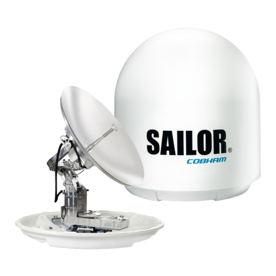
- Page 1 SAILOR 1000 XTR Ku 8W SAILOR 1000 XTR Ku 16W Installation and operation manual...
- Page 2 SAILOR 1000 XTR Ku Quick guide Installation wizard This quick guide aims at experienced service personnel who have installed the SAILOR 1000 XTR Ku system before. It lists the minimum configuration tasks you have to make before the system can be used on-air on a satellite.
- Page 3 SAILOR 1000 XTR Ku 8W SAILOR 1000 XTR Ku 16W Installation manual Document number: 98-175665-A Release date: 21 June 2021 Disclaimer...
- Page 4 In the event of any discrepancies, the English version shall be the governing text. Thrane & Thrane A/S is trading as Cobham SATCOM. Company address Thrane &...
- Page 5 The minimum safety distance to the Above Deck Unit reflector on the focal line is 30 m for SAILOR 1000 XTR Ku 8W and 47 m for SAILOR 1000 XTR Ku 16W, based on a radiation level of 10 W/m .
- Page 6 Compass Safe Distance: SAILOR 1000 XTR Ku 8W and SAILOR 1000 XTR Ku 16W antenna or ADU (Above Deck Unit): min. 170 cm (IEC 60945). SAILOR 7516A BDU (Below Deck Unit): min. 30 cm (IEC 60945). Service User access to the interior of the BDU is prohibited. Only a technician authorized by Cobham SATCOM may perform service - failure to comply with this rule will void the warranty.
- Page 7 VSAT restrictions There are restrictions in use of the frequency band 13.75 to 14 GHz in the Note following countries. Other countries may have restrictions, consult your airtime provider or relevant authorities for information. • Belgium • Hungary • Latvia •...
- Page 8 Record of Revisions Rev. Description Release Date Initials Original document 21-06-2021 98-175665-A...
- Page 9 Personnel installing or servicing the system must be properly trained and authorized by Cobham SATCOM. It is important that you observe all safety requirements listed in the beginning of this manual, and install the system according to the guidelines in this manual.
- Page 10 Some materials can be dangerous. CAUTION! Do not use materials that are not equivalent to materials specified by Cobham SATCOM. Materials that are not equivalent can cause damage to the equipment. CAUTION! The system contains items that are electrostatic discharge sensitive.
-
Page 11: Table Of Contents
Table of contents Chapter 1 Introduction SAILOR 1000 XTR Ku system ..................... 1-1 1.1.1 Above Deck Unit (ADU) ......................1-2 1.1.2 Below Deck Unit (BDU) ....................... 1-5 1.1.3 VSAT Modem ........................... 1-6 1.1.4 Satellite type approvals ....................... 1-6 1.1.5 Service activation ........................... 1-6 Part numbers and options .................... - Page 12 Table of contents Chapter 3 Interfaces Connector panel ........................... 3-1 3.1.1 AC input connector ........................3-1 3.1.2 ADU connector ..........................3-1 3.1.3 Rx/Tx connectors for VSAT modem ..................3-2 3.1.4 NMEA 0183 RJ-45 connector ....................3-2 3.1.5 GPIO RJ-45 connector ......................... 3-3 3.1.6 RS-232 RJ-45 connector ......................
- Page 13 Table of contents Chapter 6 Service Built-in test and LEDs ....................... 6-1 6.1.1 LEDs of the modules in the ADU .................... 6-1 6.1.2 LEDs in the BDU ..........................6-2 Removal and replacement of the BDU ............... 6-2 Removal and replacement of ADU modules ............6-2 Troubleshooting basics ......................
- Page 14 Table of contents C.2.7 help ...............................C-4 C.2.8 navigation ............................C-5 C.2.9 status ..............................C-5 C.2.10 system ..............................C-6 C.2.11 test ................................C-6 C.2.12 iothub ..............................C-6 Appendix D Grounding and RF protection Why is grounding required? ....................D-1 D.1.1 Reasons for grounding .........................D-1 D.1.2 Safety ..............................D-1 D.1.3 ESD Protection ..........................D-1 Grounding Recommendations ...................D-1...
-
Page 15: Introduction
Part numbers and options on page 1-7): • SAILOR 1000 XTR Ku 8W (includes 8 W BUC and can be converted to GX/Ka) • SAILOR 1000 XTR Ku 16W (includes 16 W BUC and can be converted to GX/Ka) The SAILOR 1000 XTR Ku system consists of the following units: •... -
Page 16: Above Deck Unit (Adu)
No scheduled maintenance. Few spare parts, easy to service Support for Cobham ConnectIT Prepared for third-party IP devices in ADU 1.1.1 Above Deck Unit (ADU) The SAILOR 1000 XTR Ku ADU is a 103 cm VSAT stabilized tracking antenna, consisting of a suspended antenna with a standard global RF configuration. - Page 17 SAILOR 1000 XTR Ku system Modules in the SAILOR 1000 XTR Ku ADU Figure 1-2: SAILOR 1000 XTR Ku: ADU modules 1/2 1. GNSS module (GPS, GLONASS, BEIDOU). 2. XTR Antenna Control Module (ACM). 3. ADU power on/off. 4. Cross elevation motor and encoder. 5.
- Page 18 SAILOR 1000 XTR Ku system Figure 1-3: SAILOR 1000 XTR Ku: ADU modules 2/2 11. Zero Reference Module. 12. Azimuth motor. 13. Azimuth zero reference module. 14. Rotary joint. 15. Feed horn. The antenna comes with lifting brackets pre-mounted and uses a single coax cable between the ADU and BDU.
-
Page 19: Below Deck Unit (Bdu)
SAILOR 1000 XTR Ku system all modules. The ADU performs a POST (Power On Self Test) and you can request a self test (PAST, Person Activated Self Test). Continuous Monitoring (CM) is always enabled. Error codes can be read out in the web interface and in the display of the BDU. ADU software is updated automatically when making a software update through the Below Deck Unit (BDU). -
Page 20: Vsat Modem
SAILOR 1000 XTR Ku system The BDU has a an On/Off power switch and a LAN connector at the front for accessing the service port. The unit is AC powered. 482.6 On/Off switch Service port Figure 1-5: BDU front panel Service friendly BDU You can do remote diagnostics and service with the BDU. -
Page 21: Part Numbers And Options
The following model and part numbers are available for the SAILOR 1000 XTR Ku system: Part number Model number Description 407509A-00500 7509A SAILOR 1000 XTR Ku 8W ADU 407509B-00500 7509B SAILOR 1000 XTR Ku 16W ADU 407516A-00500 7516A SAILOR XTR BDU Table 1-2: Model and part numbers for the SAILOR 1000 XTR Ku system 1.2.2 Options... -
Page 22: Installation
Chapter 2 Installation This chapter has the following sections: • What’s in the box • Site considerations • Installation of the ADU • Installation of the BDU • Installation of the VSAT modem 2.1 What’s in the box 2.1.1 To unpack Unpack the ADU and BDU. -
Page 23: Tools Needed
Site considerations 2.1.3 Tools needed The following tools may be needed during the installation: • Torx TX 30 to open the locks of the service hatch • Torque wrench to fasten the mounting bolts for the ADU • Torque wrench to fasten the N connector at the ADU •... -
Page 24: Obstructions (Adu Shadowing)
Cobham SATCOM recommends that the radome should NOT be modified or changed to another type. Exchanging or modifying the radome will not void the general warranty for material and workmanship etc. -
Page 25: Blocking Zones - Azimuth And Elevation
Site considerations 3. Elevate the ADU by mounting it on a mast or on a mounting pedestal on a deck or deck house top to avoid obstruction. Figure 2-1: Signal degradation because of obstructing objects, look angle -18° to 118° 2.2.3 Blocking zones –... -
Page 26: Safe Access To The Adu: Radiation Hazard
The radiation and safety distances are: Maximum EIRP Safety Antenna model level distance 407509A-00500 SAILOR 1000 XTR Ku 8W ADU 49 dBW 30 m 407509B-00500 SAILOR 1000 XTR Ku 16W ADU 52 dBW 47 m Table 2-1: Radiation and safety distance The safety distance is based on a radiation level of 10W/m²... -
Page 27: Ship Motion And Offset From The Ship's Motion Centre
Site considerations 2.2.5 Ship motion and offset from the ship’s motion centre When installing the ADU you must consider the mounting height carefully. The higher up the ADU is mounted, the higher is the linear g force applied to the ADU. The g force also depends on the roll period of the ship, see Table 2-2. - Page 28 Site considerations mast with bracing. In regards to stiffness the overall criterion is that the first structural mode of the mast or foundation (where the antenna system is mounted) should be above 30 Hz. All the designs presented in the following sections respect this standard. An antenna mounted on a less stiff structure might be functional, Important however, this could lead to a decrease in the operational lifetime of the...
- Page 29 Site considerations 3. Allow sufficient space so the nut is free of the welded seam and there is room for tools (min. 50 mm). Figure 2-8: ADU mast flange, distance to the welded seam CAUTION! Avoid sharp edges where the flange is in direct contact with the radome.
- Page 30 Site considerations Figure 2-10: Free mast length and bracing for a tall mast Make sure that there is free space below the drain tube. Read also Note Condensation and water intrusion on page 2-14. The tables in the next sections suggest design values for the free mast length. The tables list the values for steel masts.
- Page 31 Site considerations Max. free Outer Outer Wall Thickness mast Diameter Mast with 3 braces Diameter Thickness for brace length for brace (mm) (mm) (mm) (steel), (m) (mm) 30-40° Table 2-4: Mast dimensions with 3 braces Outer Thickness Max. free mast Outer Wall Mast with 2...
-
Page 32: Interference From Radar, Gnss, L-Band And Other Transmitters
Site considerations 2.2.7 Interference from radar, GNSS, L-band and other transmitters Do not place the ADU close to interfering signal sources or receivers. For Note allowed distances to other transmitters see Figure 2-12. It is recommended to test the total system by operating all equipment simultaneously and verifying that there is no interference. - Page 33 Site considerations “d min.” is defined as the shortest distance between the radar antenna (in any position) and the surface of the ADU. X-band (~ 3 cm / 10 GHz) damage distance SAILOR 1000 XTR Ku ADU Radar d min. at 15° vertical d min.
- Page 34 Site considerations It is strongly recommended that interference-free operation is verified before the installation is finalized. CAUTION! The ADU must never be installed closer to a radar than “d min.” - even if experiments show that interference free operation can be obtained at shorter distances than “d min.” in the previous section.
-
Page 35: Condensation And Water Intrusion
Site considerations 2.2.8 Condensation and water intrusion In some weather conditions there may occur condensation inside the radome. The drain tube is designed to lead any water away from inside the radome. 1. If possible, install the radome such that direct spray of seawater is avoided. 2. - Page 36 Site considerations SAILOR 1000 XTR Ku Cable Type Absolute max. Absolute max. length (m) length (ft) RG223-D 25 m 82 ft RG214/U 50 m 164 ft S 07272B-05 95 m 311 ft LMR-600-50 135 m 442 ft LDF4.5-50 Andrew 300 m 984 ft Table 2-8: ADU cable types and maximum lengths 1.
-
Page 37: Installation Of The Adu
Installation of the ADU 2.3 Installation of the ADU The following sections describe the installation and grounding of the ADU. The ADU is shipped fully assembled. You have to install it on the mast and attach the ADU cable. WARNING! Use a strong webbed sling with a belt to lift the ADU without damaging the radome. - Page 38 Installation of the ADU • Important: Maintain the vertical orientation of the ADU center line. • Check for potential interference, read more about this in Interference from radar, GNSS, L-band and other transmitters on page 2-11. • Always use all 4 bolts when installing the ADU. •...
- Page 39 Installation of the ADU Installation procedure To install the ADU, do as follows: 1. Install the mast with the mast flange and have the 4 M12 bolts ready. 2. Undo all shipping buckles, take off the wooden top and remove the casing. 3.
-
Page 40: To Ground The Adu
Installation of the ADU N connector Figure 2-18: Connecting the ADU cable 10. Ensure that the connector is properly protected against seawater and corrosion. As a minimum, wrap it with self-amalgamating rubber. 11. Where the cables are exposed to mechanical wear — on deck, through bulkheads, etc. – protect the cables with steel pipes. - Page 41 Installation of the ADU To ground the ADU do as follows: 1. Clean the metal underneath the head of at least one bolt of insulating protective coating and use a serrated washer to obtain a good ground connection. 2. Tighten the bolt. Use stainless steel bolts and washers. 3.
-
Page 42: Installation Of The Bdu
Installation of the BDU 2.4 Installation of the BDU The following sections describe the installation and grounding of the BDU. 2.4.1 To install the BDU To install the BDU, do as follows: 1. Slide the BDU into a 1U space in a 19” rack. 2. -
Page 43: Integration Of A 3Rd Party Ip Device
Integration of a 3rd party IP device 2.6 Integration of a 3rd party IP device The SAILOR 1000 XTR Ku is prepared for integration of 3rd party IP devices. This section describes how to integrate a 3rd party device inside the antenna radome. The antenna has three interfaces for the integration;... -
Page 44: Mechanical Interface
Integration of a 3rd party IP device 2.6.3 Mechanical interface The SAILOR 1000 XTR Ku pedestal is prepared for mounting devices on the side of the pedestal. The mounting screw holes (M5x8mm) can support a special designed mounting bracket to support mounting of a 3rd party hardware device in the antenna. Fasten the mounting bracket with 4.5 Nm. -
Page 45: Power And Startup
Power and startup 2.7 Power and startup 1. Connect power to the BDU. 2. Connect power to the VSAT modem. 3. Switch on the BDU. The unit starts up and goes through an initialization procedure: • Antenna POST pending • Antenna SW upload (If the software versions in the ADU and BDU are not the same, a software update is done during startup.) •... -
Page 46: Chapter 3 Interfaces
Chapter 3 Interfaces 3.1 Connector panel Figure 3-1: BDU: connector panel 3.1.1 AC input connector Connect the power cable to the AC power connector. Outline (on the BDU) Voltage range 100–240 VAC Earth Table 3-1: AC power connector 3.1.2 ADU connector There is just one cable from the BDU to the ADU. -
Page 47: Rx/Tx Connectors For Vsat Modem
Connector panel 3.1.3 Rx/Tx connectors for VSAT modem Connect the Rx and Tx channels of the VSAT modem to the Rx and Tx connectors of the BDU with the 2 supplied Rx/Tx cables (75 Ohm coax, F-F, 1 m). Outline Pin function (on the BDU) number... -
Page 48: Gpio Rj-45 Connector
Connector panel 3. HNHDT (Non-North seeking gyro compass) 4. IIHDT (Integrated Instrument) 5. HCHDT (Magnetic compass) Any HDT sentence is supported as long as it complies with the following header Note format: "$xxHDT" where xx can be two characters e.g. IN for $INHDT. Recommended NMEA 0183 cable: Ethernet Cat. -
Page 49: Rj-45 Connector
Connector panel 3.1.6 RS-232 RJ-45 connector Use the following connector to connect the BDU to the VSAT modem. Outline Signal Pin function RSSI 2 Analog (0 - 14 VDC) DTR/Rx Lock Modem Rx lock Receive data Ground Ground Transmit data DSR/TX Mute Tx mute RSSI 1 Analog (0 - 14 VDC) Shield... -
Page 50: Lan Connectors
Connector panel 3.1.8 LAN connectors The BDU has four Ethernet connectors (type RJ-45), located at the back of the unit, for PC/laptops, routers, wireless access points. LAN port 5 is for service access at the front. Depending on the VSAT modem, one LAN connector may be used for modem control. The maximum cable length per connection is 100 m. -
Page 51: Chapter 4 Setup Of The Antenna
Chapter 4 Setup of the antenna This chapter has the following sections: • Introduction to the web interface • Settings • Service • Keypad and menus of the BDU • Startup sequence The SAILOR 1000 XTR Ku system is not designed to be connected directly to Important the Internet. -
Page 52: Connecting To The Web Interface
Introduction to the web interface The following figure shows the menu items of the sections Settings (left) and Service (right). Figure 4-2: Menu items in Settings (left), Service (right) 4.1.1 Connecting to the web interface To connect to the web interface do as follows: 1. - Page 53 Introduction to the web interface There is an admin and a guest login. A guest can only access the functions that are allowed by an administrator. With the guest login (user name: guest, password: configured by the administrator) you can protect the system from accidental changes of the configuration. Sections on the Dashboard Parameter Description...
- Page 54 Introduction to the web interface Parameter Description GNSS position latitude Current position of the vessel, reported by built-in GNSS module or external GPS source. GNSS position altitude Current position of the vessel, reported by built-in GNSS module or external GPS source. Vessel heading Ship's heading in degrees with reference to North, provided by ship's gyro.
-
Page 55: Settings
Settings Icon Explanation System messages, number of active errors and warnings. Mouse over will show a list of the first 5 messages, a click on the list will display the event list. About and contact information Logout Table 4-2: Icons in the top bar (Continued) 4.2 Settings In this section you can define a VSAT profile, enter navigation input, set the blocking zones and define settings for added third-party equipment mounted in the antenna. -
Page 56: Modem Types
Settings 3. At VSAT profile name enter a name of your choice. 4. Select the modem from the Modem type drop down list. 5. Fill in the data for your modem setup and desired tracking options. 6. Click the Save icon to save the VSAT profile. 7. - Page 57 Settings SatLink 2910 Modem To set up the modem type SatLink 2910, do as follows: Figure 4-9: Setup of SatLink 2910 Modem 1. Select the appropriate BUC reference. Recommended setting is: TX 10 MHz. Options are: • TX 10 MHz, supplied from modem TX connector •...
- Page 58 Settings Generic Modem To set up the modem type Generic, do as follows: Figure 4-10: Setup of Generic Modem Use the generic modem profile with any type of single beam VSAT modem. 1. Select the BUC reference. Recommended setting is: TX 10 MHz Options are: •...
- Page 59 3° 3° 3° Table 4-3: SAILOR 1000 XTR Ku 8W: Elevation cutoff (in degrees) versus VSAT modem bandwidth and power a. Eirp = Fixed system gain 44 dB + antenna gain @ 14.25 GHz 41.4 dB + modem power Bandwidth...
-
Page 60: Network Settings
Settings Bandwidth Nominal modem power 16384 kHz 2° 2° 3° 3° 4° 5° 6° 7° 8° 32768 kHz 2° 2° 2° 3° 3° 4° 4° 5° 6° Table 4-4: SAILOR 1000 XTR Ku 16W: Elevation cutoff (in degrees) versus VSAT modem bandwidth and power (Continued) a. -
Page 61: Navigation
Settings DNS setup If you have access to a Domain Name Server (DNS) you can specify the address of the e- mail server by using the server name instead of its IP address. This can be used in Outgoing mail server in E-mail setup (secure e-mail) on page 4-18. You may statically specify the address of one or two DNS. - Page 62 Settings Figure 4-12: Settings, Navigation (Heading and Position), (example) 2. Select a heading mode. Heading Description mode External Heading input from the vessel’s gyro compass (default). If there is no heading input due to failure, alarms are raised and the antenna continues in gyro-free mode.
-
Page 63: Operation In Gyro-Free Mode
Settings Position mode Description Mode Select one of the following: • GNSS (default) • Manual • External GNSS Select one of the following: • GPS (default) • BEIDOU • GPS + BEIDOU • GLONASS • GPS + GLONASS Latitude, Longitude, Altitude Enter the values if you have set the Position Mode to Manual. -
Page 64: Acquisition Process And Search Pattern
Settings Tracking for satellite elevation between 5 and 75 degrees When the system has found the satellite and is in pointing mode, the performance of a system with heading input and a system without heading input will be very similar. Note that this is only the case for a satellite elevation range from 5 to 75 degrees. - Page 65 Settings With heading input or fixed heading, Inclined Orbit Satellite 1. The antenna starts the acquisition, searches for 10 seconds at the expected position. If RX lock is detected the antenna goes to Tracking. 2. If no RX lock is detected, a box search pattern is started and the positions where RF power can be received are stored.
-
Page 66: Blocking Zones
Settings 4.2.7 Blocking zones You can define blocking zones, i.e. No TX and RX zones by entering azimuth and elevation angles for each blocking zone. The system’s blocking map is built up over some weeks and shows where the actual blocking zones are. This is useful if the antenna looses the signal frequently and you might want to check whether the blocking zones are set up correctly. - Page 67 Settings Blocking map for optimization of blocking zones The blocking map is intended as a tool to optimise the blocking zones in order to reduce the antenna’s downtime. It shows the active blocking zones and an automatic evaluation of the antenna reception.
-
Page 68: Iot & Management
Settings 4.2.8 IoT & management On this page you can set up e-mail, remote syslog, SNMP, diagnostics and statistics reporting, and IoT. Figure 4-18: Settings, IoT & management (example) E-mail setup (secure e-mail) To be able to send e-mails you must set up some parameters. Select SMTP to use insecure Simple Mail Transfer Protocol. - Page 69 1. Click the link SNMP MIB file download. 2. Save the file on your computer. You can also download the BDU MIB from Cobham eSupport web site. Diagnostics report This report contains information from the ADU and BDU that are relevant for the service personnel during troubleshooting.
- Page 70 Settings intervals. You can send automatically generated diagnostic reports at fixed intervals. It is also useful documentation of the current setup and contains all parameters set during configuration. The main sections of the diagnostics report are: • Software • System •...
- Page 71 BDU serial number ADU SN ADU serial number SW ver. Software version System type SAILOR 1000 XTR Ku 8W (example) Table 4-10: Statistics report, header record Parameter recorded Description UTC. (s) UTC in seconds and date format for the data set.
-
Page 72: Dual Antenna
Settings Parameter recorded Description Rx Lock (%) Rx locked and logon time, in percent, for the sampling Logon (%) interval. Pos Ok (%) Valid position, in percent of the sampling interval. VMU Connection (%) Link with VSAT modem, in percent of the sampling interval. - Page 73 Settings • To set up permissions for guest user • BDU Config • Factory default To change a password On the page User administration you can change the password for admin or guest. Figure 4-20: User administration, change password for admin To change the current password, do as follows: 1.
- Page 74 Settings Figure 4-21: Permissions for guest users To set up the user permissions, do as follows: 1. From the left navigation pane, select Settings > User administration. 2. Click the pen icon for guest 3. For each item under Allow user to: select •...
-
Page 75: Installation Wizard
Settings 4.2.11 Installation wizard The installation wizard starts automatically after you have logged in for the first time. You can step through the necessary steps to set up the antenna. You can start the installation wizard at any time from the section Settings. Figure 4-22: Installation wizard 1. -
Page 76: Service
Service 4.3 Service 4.3.1 Software In this section you can manage software versions, upload and save configurations and reset the SAILOR 1000 XTR Ku to factory default. Figure 4-23: Service - Software Upload The following items are required before the software can be updated: •... - Page 77 Service 4. Type in the user name (admin or guest) and password. 5. The web interface opens directly with the Dashboard page. 6. Click Service in the top bar. The Software page is displayed. 7. Click Choose file and locate the new software file. 8.
- Page 78 Service To import and export a system configuration If you need to reuse a configuration in another SAILOR 1000 XTR Ku, you can save the current configuration to a file, which can then be loaded into another SAILOR 1000 XTR Ku. You can also use this feature for backup purposes.
-
Page 79: Calibration
Service 2. Locate the section BDU Config. 3. At Load config from BDU click Load. 4.3.2 Calibration Before the SAILOR 1000 XTR Ku can be used you must select a heading input in order to make an azimuth and cable calibration. The azimuth calibration is required in order to determine the offset of the ADU zero direction to the bow-to-stern line of the ship. - Page 80 Service Automatic azimuth calibration with an active VSAT profile You can enable automatic azimuth calibration, even if there is no line of sight to an azimuth calibration satellite from the place of installation. To use this feature you must have made a valid VSAT profile and have activated it.
- Page 81 Service 6. Click Start and wait typically 5 minutes for the calibration to finish. A message is displayed when the calibration has completed. In case of failure, see the table in the following section for a description of error codes during calibration. It is strongly recommended to verify the result of a calibration performed Important with user defined data.
- Page 82 Service attenuation margin is left for the antenna cable. This indicates whether the antenna cable and connectors are in good condition and well crimped. The SAILOR 1000 XTR Ku is calibrated now. If the calibration failed there will be a message. If input from the vessel’s gyro compass is not available: Change the heading Important input setting from Fixed to None at Heading –...
-
Page 83: Flow Chart For Calibration (User Controlled)
Service 4.3.3 Flow chart for calibration (user controlled) The following flow chart gives an example of the steps in a user controlled azimuth and cable calibration. SAILOR XTR ready to power on, ADU and BDU connected. Connect ship heading, if present Final heading source? Power On SAILOR XTR. -
Page 84: Modem
Service 4.3.4 Modem For ease-of-use, you can access the modem (e.g. modem web interface) through the BDU using port forwarding. To make the modem accessible via the BDU, do as follows: Figure 4-27: Service - Modem 1. In the BDU web interface, select Service > Modem. 2. -
Page 85: Line Up
Service 4.3.5 Line up The SAILOR 1000 XTR Ku has been tested at the factory and online on a live satellite link to calibrate the TX polarization unit. You can fine-tune the TX polarization by doing a line up. Figure 4-28: Service - Line up The ship must not move during the line-up procedure. -
Page 86: Fixed Tx Gain Principle
Figure 4-29: Fixed TX gain principle Example: BDU Tx-port power: SAILOR 1000 XTR Ku 8W: -5 dBm, BUC output: +39 dBm (Fixed gain = 44 dB) SAILOR 1000 XTR Ku 16W: -5 dBm, BUC output: +42 dBm (Fixed gain = 47 dB) 4.3.7 Events This page shows a detailed list of active events and notifications including the time of the first occurrence, ID and severity of the event message, and a short text describing the error. -
Page 87: Support
Service Figure 4-30: Service - Event list (example) 4.3.8 Support On this page you can download this manual as pdf, download various reports and start a self test of the antenna. You can enable extra diagnostic logging, i.e. include data for modem communication in the diagnostics report. -
Page 88: Keypad And Menus Of The Bdu
Keypad and menus of the BDU BUC TX information The BUC TX information is displayed on the Dashboard in the section TX. BUC TX indicates if the SAILOR 1000 XTR Ku has enabled the BUC or not. It can show On or Off. This information is also shown in the display of the BDU as TX ON or TX OFF. -
Page 89: List Of Menus
Description MAIN View with current status of the SAILOR 1000 XTR Ku 8W. This view is displayed after a time out of 10 minutes. Press any key (except left arrow) to enter the menu at MAIN. New events are shown in this display. - Page 90 Current IP address for LAN 1 and LAN 2. MASK 1/2 Current netmask for LAN 1 and LAN 2. PORT 3 IP (LAN 3) Current IP address of the SAILOR 1000 XTR Ku 8W web interface (default: 192.168.0.1). Table 4-17: NETWORK menu of the BDU 98-175665-A...
- Page 91 Keypad and menus of the BDU NETWORK Description MASK 3 (LAN 3) Current netmask of the SAILOR 1000 XTR Ku 8W web interface (default: 255.255.255.0). PORT 4 IP Current IP address for LAN 4. MASK 4 Current netmask for LAN 4.
-
Page 92: Startup Sequence
Startup sequence 4.5 Startup sequence Once the system is configured and a VSAT profile is active, the startup sequence is as follows: • Antenna POST pending • Antenna SW upload (If the software versions in the ADU and BDU are not the same, a software update is done during startup.) •... -
Page 93: Chapter 5 Installation Check Lists
Chapter 5 Installation check lists Use the following sections to verify that the system is ready for customer delivery. 5.1 Installation check list: Antenna Step Task Further information Done Check that the antenna is free of See Obstructions (ADU obstructions. shadowing) on page 2-3. -
Page 94: Installation Check List: Bdu, Connectors And Wiring
Installation check list: BDU, connectors and wiring 5.2 Installation check list: BDU, connectors and wiring Verification and further Step Task Done information Check that the BDU is grounded See To ground the BDU on correctly, using the mounting bolts and page 2-21 and washers. -
Page 95: Installation Check List: Functional Test In Harbor
Installation check list: Functional test in harbor 5.3 Installation check list: Functional test in harbor Step Task Further information Done Check that the antenna is tracking The logon LED in the BDU display the satellite must be steady green and the display shows: TRACKING. -
Page 96: Chapter 6 Service
Chapter 6 Service This chapter has the following sections: • Built-in test and LEDs • Removal and replacement of the BDU • Removal and replacement of ADU modules • Troubleshooting basics • Returning units for repair 6.1 Built-in test and LEDs The ADU and the BDU have a Built-In Test Equipment (BITE) function in order to make fault diagnostics easy during service and installation. -
Page 97: Leds In The Bdu
Table 6-2: LEDs on the BDU 6.2 Removal and replacement of the BDU There are no parts in the BDU that you can remove or replace. Contact your Cobham SATCOM service partner for repair or replacement. 6.3 Removal and replacement of ADU modules All replacement of modules must be done by a Cobham SATCOM service partner. -
Page 98: Troubleshooting Basics
Troubleshooting basics 6.4 Troubleshooting basics 6.4.1 Overview This section describes an initial check of the primary functions of the SAILOR 1000 XTR Ku system, and provides some guidelines for troubleshooting. Generally, if a fault occurs without any obvious reason, it is always recommended to observe the LEDs and the BDU display showing the active events. -
Page 99: Returning Units For Repair
COBHAM SYNC PARTNER PORTAL, which may help you solve the problem. Your dealer, installer or Cobham SATCOM partner will assist you whether the need is user training, technical support, arranging on-site repair or sending the product for repair. Your dealer, installer or Cobham SATCOM partner will also take care of any warranty issue. -
Page 100: Appendix A Technical Specifications
Appendix A Technical specifications This appendix has the following sections: • Specifications • Patents • Outline drawings • VSAT LNB Data Sheet (physical LNB) • VSAT 8W BUC Data Sheet • VSAT 16W BUC Data Sheet 98-175665-A... -
Page 101: Specifications
Specifications A.1 Specifications SPECIFICATIONS Frequency band Ku-Band Reflector size 103 cm Certification Compliant with CE (Maritime), ETSI System power supply range 100 - 240 VAC, 50-60 Hz Total system power consumption 480 W peak, 320 W typical FREQUENCY BAND 10.70 to 12.75 GHz 13.75 to 14.50 GHz (extended band) ANTENNA CABLE &... -
Page 102: Patents
X7 iDirect iQ200 Newtec MDM2510 SatLink 2900/2910 A.2 Patents The patents listed below apply to SAILOR 1000 XTR Ku 8W and SAILOR 1000 XTR Ku 16W Patent application number Description 11749202.5; 10-2013- An assembly comprising a movable and 7008607; 13/819,621... -
Page 103: Outline Drawings
Outline drawings A.3 Outline drawings A.3.1 ADU SAILOR 1000 XTR Figure A-1: Outline drawing: ADU 98-175665-A Appendix A: Technical specifications... -
Page 104: Bdu
Outline drawings A.3.2 BDU Figure A-2: Outline drawing: BDU 98-175665-A Appendix A: Technical specifications... -
Page 105: Vsat Lnb Data Sheet (Physical Lnb
VSAT LNB Data Sheet (physical LNB) A.4 VSAT LNB Data Sheet (physical LNB) The following table shows the data of the LNBs which are fitted in the ADU. The SAILOR 1000 XTR Ku is designed to make any Ku Band frequency in the range of 10.7 GHz to 12.75 GHz available to a VSAT modem by allowing the user to select the LNB LO of his choice –... -
Page 106: Vsat Lnb User Installation And Configuration Information
VSAT LNB Data Sheet (physical LNB) A.4.1 VSAT LNB user installation and configuration information The SAILOR 1000 XTR Ku can interpret 4-band LNB switching signals and exact LO information acquired directly from the attached VSAT modem by means of a data connection. -
Page 107: Vsat 8W Buc Data Sheet
VSAT 8W BUC Data Sheet A.5 VSAT 8W BUC Data Sheet SAILOR 1000 XTR Ku 8W (NJT8318UNMR) 1. Electrical Specifications 1 1. Output Frequency Range 13.75 to 14.5 GHz 1 2. Input Frequency Range 950 to 1,700 MHz Maximum IF Input Level 1 3. - Page 108 VSAT 8W BUC Data Sheet GREEN: L.O. locked RED: L.O. unlocked 1 25. LED Indicator (or no 10 MHz reference signal) Monitor and Control <RS 232C Interface M&C > RS 232C Interface on MS connector [Interface] Monitor: [Functions] Tx Output Power / Temperature / Tx Status / Alarm (Over temperature) / L.O.
-
Page 109: Vsat 16W Buc Data Sheet
VSAT 16W BUC Data Sheet A.6 VSAT 16W BUC Data Sheet SAILOR 1000 XTR Ku 16W (NJT8319UNMR) 1. Electrical Specifications 1 1. Output Frequency Range 13.75 to 14.5 GHz 1 2. Input Frequency Range 950 to 1,700 MHz Maximum IF Input Level 1 3. - Page 110 VSAT 16W BUC Data Sheet GREEN: L.O. locked RED: L.O. unlocked 1 25. LED Indicator (or no 10 MHz reference signal) Monitor and Control RS 232C Interface on MS connector <RS 232C Interface M&C > Monitor: [Interface] Tx Output Power / Temperature / Tx Status [Functions] / Alarm (Over temperature) / L.O.
-
Page 111: Appendix B Vsat Modem Settings
Appendix B VSAT modem settings In this appendix you find detailed information how to optimize performance in blockage situations and how to set up supported VSAT modems. The appendix has the following sections: • Performance optimization for blockage • OpenAMIP setup •... - Page 112 Performance optimization for blockage Better blockage communication A major disadvantage of this single signal is that if the VSAT modem has multiple satellites to choose from, then, when selecting a new satellite, the VSAT modem is again relying on the simple time-out. This continues until a satellite with no obstruction in the view from the satellite terminal is selected.
-
Page 113: Protocol And Interfaces
OpenAMIP setup B.2 OpenAMIP setup B.2.1 Protocol and interfaces Introduction The following sections describe the protocol and interface between the SAILOR 1000 XTR Ku BDU and OpenAMIP VSAT modem. OpenAMIP operation is normally used by service providers offering global VSAT service as the protocol supports roaming between satellites (Automatic Beam Switching). - Page 114 OpenAMIP setup OpenAMIP Message # Parameters Description Message originator Modem Where (location) interval Antenna Alive interval Antenna CNR reporting rate Antenna Functional, May transmit, Search count Antenna Valid, latitude, longitude, time Table B-1: Supported OpenAMIP commands (Continued) For more detailed information contact iDirect for latest OpenAMIP standard. Messages from VSAT modem Explanation S -15.000000 0.000000 0.000000...
-
Page 115: Configuration Example (Openamip
OpenAMIP setup B.2.2 Configuration example (OpenAMIP) Examples of modem profile and satellite configuration from the web interface are shown in the figures below. Add a VSAT profile (Settings > VSAT profiles) as shown below Figure B-1: VSAT profile, OpenAMIP (example) 98-175665-A Appendix B: VSAT modem settings... -
Page 116: Satlink 2910 Vsat Modem
(5990). (zero) odu antenna 30 This configures the antenna type to a Thrane & Thrane / Cobham SATCOM antenna. This configures the BUC type to a SAILOR VSAT odu txtype 62 odu lnb 62 This configures the LNB type to SAILOR VSAT LNB... -
Page 117: Bdu Configuration
SatLink 2910 VSAT modem Command Description dvb tx autostart on This will enable modem tx. Save the new ODU Configuration: This will save the above settings to flash in the save config modem. And restart the modem: restart Table B-4: Configuration of the SatLink 2910 VSAT modem (Continued) Example: odu antctrl show Antenna Controller Configuration... -
Page 118: Appendix C Command Line Interface
Appendix C Command line interface C.1 Introduction After you have done the initial configuration and connected the SAILOR 1000 XTR Ku to your network, you can use SSH to configure the SAILOR 1000 XTR Ku. You can also set up VSAT modem parameters. -
Page 119: Supported Commands
Supported commands Conventions The command description below uses the following special typography: Convention Description Courier font Information that is displayed on the screen. Bold Courier font Text the user must enter. Required argument <argument> Optional argument [argument] Table C-1: Command typography Example: navigation heading [mode [value]] C.2 Supported commands... - Page 120 Supported commands C.2.1 antenna_data Command Description Shows detailed information of this specific command. antenna_data Shows current antenna type. Example output: antenna_data type UCLI:/$ antenna_data type System: 7509D Type: Oem: inmarsat sub type: 0 lnb type: 1 buc type: 4 antenna type [<adu-id> [<sub-type>]]: sets the antenna antenna_data type type and the optional sub-type.
-
Page 121: Demo
Supported commands C.2.4 demo Command Description Shows detailed information of this specific command. demo Starts a demo pattern where the antenna will turn azimuth, demo start elevation and cross elevation until it receives the command demo stop. Stops the antenna demo pattern. demo stop Resets the antenna to angle 0. -
Page 122: Navigation
Supported commands Command Description Shows the sub commands, unit and description for the help demo command demo Shows the sub commands, unit and description for the help dual command dual antenna antenna Shows the sub commands, unit and description for the help exit command exit Table C-8: UCLI command: help (Continued) -
Page 123: System
It makes a power-on self test and then points to the last used satellite. Shows the software version, part names and serial numbers of the system info SAILOR 1000 XTR Ku 8W. Table C-11: UCLI command: system C.2.11 test Command Description Shows detailed information of this specific command. -
Page 124: Appendix D Grounding And Rf Protection
D.1 Why is grounding required? D.1.1 Reasons for grounding Grounding the SAILOR 1000 XTR Ku 8W system is required for at least two reasons: • Safety: Lightning protection of persons and equipment. • Protection: ESD (ElectroStatic Discharge) protection of equipment. -
Page 125: To Ground The Adu
Grounding Recommendations The foil must be at least 0.1 mm thick. Note Connect the foil to the hull by plenty of screws or hard–soldering. Run the foil past the place where the short ADU cable is to be grounded and mount a grounding kit on top of the foil. -
Page 126: Alternative Grounding For Steel Hulls
Alternative grounding for steel hulls not possible on e.g. fiberglass hulls (nor is it preferable on aluminium hulls) a number of alternative grounding methods are suggested in the following paragraphs. D.3 Alternative grounding for steel hulls The following guidelines assume a two-wire, isolated grounding arrangement; that is no part of the circuit, in particular the battery negative, is connected to any ground potential or equipment. - Page 127 Alternative grounding for steel hulls Recommended Alternative Antenna Antenna Base Plate Base Plate (Antenna isolated (electrically bonded to from the the hull) the hull though the mast) Antenna grounded Antenna grounded with mounting bolts with separate cable Mast Mast (electrically bonded (electrically bonded to the steel hull) to the steel hull)
-
Page 128: To Ground The Adu
Alternative grounding for aluminum hulls D.4 Alternative grounding for aluminum hulls The following guidelines assume a two-wire, isolated grounding arrangement; that is no part of the circuit, in particular the battery negative, is connected to any ground potential or equipment. D.4.1 To ground the BDU The BDU should preferably be grounded with the short cable. -
Page 129: Alternative Grounding For Fiber Glass Hulls
The BDU should preferably be grounded with the short ADU cable and a grounding kit (available from Cobham SATCOM). Further, the BDU must be grounded at its grounding stud in order to ensure a proper grounding if the short ADU cable is disconnected. -
Page 130: Separate Ground Cable
Separate ground cable D.6 Separate ground cable D.6.1 Ground cable - construction When dealing with electrical installations in a marine environment, all wiring must be done with double insulated, tinned strands, high quality and if exposed also UV resistant cables. This shall also apply to the separate ground cable mentioned in the previous paragraphs. -
Page 131: Ground Cable - Connection
Separate ground cable D.6.2 Ground cable - connection Mount the ground cable close to and parallel to the shielded coax cable thus minimizing ground loop problems. If possible, route the coax cable and the ground cable in metal conduits bonded to the hull or within a mast (depending on the actual installation). The ground cable must be connected at one of the mounting/grounding bolts on the ADU. -
Page 132: Jumper Cable For Grounding
Jumper cable for grounding D.7 Jumper cable for grounding Figure D-9: Jumper cable for grounding (specifications) 98-175665-A Appendix D: Grounding and RF protection... -
Page 133: Rf Interference
Interference induced from nearby high-power RF transmitters might cause system failures and in extreme cases permanent damage to the SAILOR 1000 XTR Ku 8W equipment. If there are problems with interference from HF transmitters, it is advisable to mount ferrite clamps on the coax cable in order to provide suppression of induced RF. -
Page 134: Appendix E Event Messages
Appendix E Event messages E.1 Overview The SAILOR 1000 XTR Ku 8W detects events during • POST (Power On Self Test) – a self test performed at every power-up. • Self test – started in the web interface • CM (Continuous Monitoring) – automatically performed while the system is in operation. -
Page 135: List Of Events
List of events E.2 List of events (10-06-2021) Module Type Description Explanation 08061-0 WARNING VMU linux shell The specified password (root) for the satellite password modem is not accepted by the modem. 08062-0 WARNING VMU debug shell The specified password (user) for the satellite password modem is not accepted by the modem. - Page 136 List of events Module Type Description Explanation 08078-0 WARNING VMU TX frequency The satellite modem did not provide a Tx invalid frequency, or it is invalid. A default Tx frequency is assumed, but this may degrade Tx performance. To remove this warning re-configure the modem to provide the correct Tx frequency.
- Page 137 List of events Module Type Description Explanation 08113-0 ERROR APSM production APSM production data is corrupted. data 08114-0 ERROR ASCM FS File system partition corrupt 0850A-0 ERROR GNSS Initialization GNSS initialization failed. 0851E-0 ERROR Sensor sanity Too many invalid values measured by the ISM during initialisation.
- Page 138 List of events Module Type Description Explanation 0853A-0 WARNING GNSS device error Local GNSS device error. 0853F-0 WARNING AMB timing This indicates a busy situation. It may occur during installation procedures. No user interaction is required unless it occurs repeatedly. 08540-0 WARNING VIM cable attn The output power cannot be controlled correctly.
- Page 139 List of events Module Type Description Explanation 08559-0 WARNING Azi cal. limits Check limits of the calibration result for the azimuth axis are exceeded. Pointing performance may be degraded. Info: 0x00000040: End stop detected before expected limit 0x00000100: Zero width is low 0x00000200: Zero width is high 0x00000400: Zero slack is high...
- Page 140 List of events Module Type Description Explanation 08566-0 ERROR OMT error Problem with OMT. Temperature out of range or OMT cable may be broken. 08567-0 WARNING Automatic stow The antenna automatically stowed because it detected significant movement. 08568-0 WARNING Polarisation tuning Polarisation tuning was not successful.
- Page 141 List of events Module Type Description Explanation 08A02-0 WARNING GX Core Module The Core Module temperature is out of range. This temperature may affect performance, and the Core Module will be shut down if the situation gets worse. If the "GX core module heating"...
- Page 142 List of events Module Type Description Explanation 0A108-0 Antenna ERROR ISCM Prod data Internal production data invalid. 0A180-0 Antenna ERROR ISCM Fan error BUC fan failure. Check fan movement. 0A181-0 Antenna ERROR ISCM No response No communication with ISCM. Check cable. 0A200-0 Antenna ERROR Azi Motor prod data...
- Page 143 List of events Module Type Description Explanation 0A480-0 Antenna ERROR Ele Motor Driver fault Driver could not move antenna. Check free movement of the antenna. 0A481-0 Antenna ERROR Ele Motor Power fault No power to motor driver. Check input power to system.
- Page 144 List of events Module Type Description Explanation 0B065-0 APSM ERROR APSM EBUS Temperature too high. EBUS shut down. temperature failure 0B066-0 APSM WARNING APSM LNB Temperature too high. temperature warning 0B067-0 APSM ERROR APSM LNB Temperature too high. LNB shut down. temperature failure 0B068-0 APSM...
- Page 145 List of events Module Type Description Explanation 0B0A0-0 APSM ERROR APSM No communication with APSM. Check internal Communication error connections in ACM. 0B0A1-0 APSM ERROR BDCM No communication with BDCM. Check main Communication error antenna cable. 0E000-0 AIMO ERROR AIM-O Startup of communication with AIM-O failed.
-
Page 146: Appendix F Dvb-S Satellites
Appendix F DVB-S satellites This appendix contains examples of DVB-S satellite data for azimuth calibration. Satellite Satellite Symbol VSAT coverage name position polarization frequency rate Americas EchoStar9/ 121°W Vertical 12.016 GHz 20.000 MS/s Galaxy23 Europe & Hispasat 30°W Vertical 12.052 GHz 27.500 MS/s Americas East Asia... - Page 147 Satellite Satellite Symbol VSAT coverage name position polarization frequency rate Europe Astra 4A 4.8°E Horizontal 12.637 GHz 14.468 MS/s Europe Astra 1N 19.2°E Horizontal 12.032 GHz 27.500 MS/s China Apstar6 134°E Transponder Vertical 12.435 GHz 27.500 MS/s Backup Vertical 12.675 GHz 27.500 MS/s Australia Optus D1...
- Page 148 Satellite Satellite Symbol VSAT coverage name position polarization frequency rate China, Japan, Apstar 2R 76.5°E Vertical 11.167 GHz 45.000 MS/s Korea, Burma (Telstar 10) / Apstar 7 Osaka, Japan, KT 5 113°E Vertical 12.430 GHz 25.6 Ms/s Philippines, Korea Table F-1: Examples of DVB-S satellites for azimuth calibration (Continued) For satellite data of other regions or transponders see www.lyngsat.com.
-
Page 149: Appendix G Approvals
16W: • CE (RED) G.2 CE (RED) The SAILOR 1000 XTR Ku 8W and the SAILOR 1000 XTR Ku 16W are CE certified (RED directive) as stated in the “EU Declaration of Conformity”, enclosed in copy on the next page. - Page 150 CE (RED) 98-175665-A Appendix G: Approvals...
- Page 151 Glossary Glossary Antenna Control Unit ACU Digital Module. A main processor board in the ACU. Above Deck Unit AIMO Antenna Interface Module AMIP Antenna-Modem Interface Protocol APSM Antenna Power Supply Module BDCM BDU Control Module Below Deck Unit BEIDOU Chinese satellite navigation system BIMO BDU Interface MOdule BIMO...
- Page 152 Glossary Keyboard and Display Module of the ACU Local Area Network Light Emitting Diode LGPL Lesser General Public License Low Noise Block Local Oscillator. LO frequency used by BUC and LNB. Long-Term Evolution (also called 4G) Management Information Base NMEA National Marine Electronics Association (standard) Object Identifier, in the context of the Simple Network Management Protocol (SNMP), consists of the object identifier for an object in a Management Information Base (MIB).
- Page 153 Index Index access baud rate limit 4-23 NMEA 0183 3-2 ACMAntenna Control Module 4-11 acquisition connector panel, overview 3-1 gyro-free 4-15 description 1-5 search pattern 4-14 grounding 2-21 search pattern, inclined orbit 4-15 LED 6-1 time 4-15 LEDs, display and keypad 3-1 administrator BDU display login, web interface 6-3...
- Page 154 Index calibration corrosion azimuth 4-29 smoke deposits 2-14 cable 4-29 country restrictions error codes 4-31 VSAT -v flow chart 4-33 satellite data 4-30 calibration data 4-28 default reset 4-28 reset to factory settings 4-28 China satellite F-2 default gateway 4-11 cleaning the radome 2-14 degradation CLI C-1...
- Page 155 Index factory default heading input calibration data 4-28 external 4-12 reset 4-28 fixed 4-12 failure states gyro compass 4-12 view 6-3 NMEA 3-2 none 4-12 4-13 distance from antenna 2-13 help interference 2-13 command line interface C-1 host name 4-21 4-40 elevation angle 4-9 humidity in antenna 2-14...
- Page 156 Index LO frequencies 4-38 A-10 NMEA 0183 LO stability A-6 baud rate 3-2 load none configuration 4-28 heading input 4-12 4-13 login notifications 4-36 administrator, web interface 6-3 NSS6 satellite F-1 logon administrator, command line interface C-1 obstructions distance and size 2-3 mail server OpenAMIP setup 4-18...
- Page 157 Index SatLink 2910 setup B-6 radar SatMex6 satellite F-1 distance from antenna 2-11 save signal degradation 2-12 configuration 4-28 radiation -iii self test 1-5 radiation level 2-5 send e-mail radome diagnostic report 4-20 cleaning 2-14 server setup recover SMTP 4-18 software update 4-27 service report...
- Page 158 Index status messages 6-1 steel hulls warning messages E-1 grounding D-3 warranty 6-4 steel type web interface mast 2-6 connect 4-2 STM Satlink 2900 LAN connector 3-5 examples B-7 web mmi STM Satlink 2900 VSAT modem LAN connector 3-5 setup B-6 Wiring 3-1 syslog setup 4-19...
- Page 159 98-175665-A www.cobhamsatcom.com...
Need help?
Do you have a question about the SAILOR 1000 XTR Ku 8W and is the answer not in the manual?
Questions and answers