Table of Contents
Advertisement
Quick Links
Advertisement
Table of Contents

Related Manuals for AXIOMTEK IFB112


Summary of Contents for AXIOMTEK IFB112
- Page 1 IFB112 Hardware User’s Manual...
- Page 2 Axiomtek does not make any commitment to update the information in this manual. Axiomtek reserves the right to change or revise this document and/or product at any time without notice.
-
Page 3: Safety Precautions
Most electronic components are sensitive to static electrical charge. Disconnect the power cord from the IFB112 before making any installation. Be sure both the system and the external devices are turned OFF. Sudden surge of power could ruin sensitive components. Make sure the IFB112 is properly grounded. -
Page 4: Classification
Classification Degree of production against electric shock: not classified Equipment not suitable for use in the presence of a flammable anesthetic mixture with air or with oxygen or nitros oxide. Mode of operation: Continuous Type of protection against electric shock: Class I equipment General Cleaning Tips You may need the following precautions before you begin to clean the computer . -
Page 5: Cleaning Tools
Cleaning Tools Although many companies have created products to help improve the process of cleaning your computer and peripherals users can also use household items to clean their computers and peripherals. Below is a listing of items you may need or want to use while cleaning your computer or computer peripherals. -
Page 6: Scrap Computer Recycling
Axiomtek distributor as soon as possible for the suitable solution. For the computers that are no longer useful or no longer working well, please contact your Axiomtek distributor for recycling and we will make the proper arrangement. -
Page 7: Table Of Contents
Table of Contents Safety Precautions ..................iii Classification ....................iv General Cleaning Tips ................. iv Cleaning Tools ....................v Scrap Computer Recycling ................. vi CHAPTER 1 INTRODUCTION ..........1 General Description ..............1 System Specifications ............... 2 1.2.1 CPU ........................2 1.2.2 System Memory .................... - Page 8 This page is intentionally left blank. viii...
-
Page 9: Chapter 1 Introduction
C for using in extreme operating environment and industrial automation applications. IFB112 features 1 RS-232/422/485 serial ports, 1 CAN bus, dual LANs, 1 DIO Port (2- In/1-Out), 1 eMMC 4GB onboard. Its vertical din-rail form factor makes it easy to install the system in a small cabinet. -
Page 10: System Specifications
IFB112 User’s Manual System Specifications 1.2.1 Low power RISC-based module (iMX6UL), ARM Cortex-A7 RISC-based 528MHz Processor 1.2.2 System Memory 1 x DDR3 256MB SDRAM onboard 1.2.3 Console Port For user setting with debug Connected to DIO terminal Block 1.2.4... -
Page 11: Com
IFB112 User’s Manual 1.2.8 DB9 Pin define RS232/RS422/RS485 (COM1) COM with TX/RX/RTS/CTS signals RS-232/422/485 Interface select by software COM1 RS-232 RS-422 RS-485 Data- Data+ Ground Ground Ground 1.2.9 DB9 Connector CAN bus 2.0 B Ports ... -
Page 12: Power
IFB112 User’s Manual 1.2.10 Power DC input range 9~48V Power consumption 9~48VDC, 0.55A~0.1A 0.55A@9V 0.1A@48V 0.4A@12V DC Terminal Block DC Signal Name Power+ Power- 1.2.11 Digital I/O,Relay,Console Connector and Pin Definition 2 DI/ 1DO ... - Page 13 IFB112 User’s Manual DIO 2-IN/1-OUT of TB10 Female with relay and comsole port. IFB112 DIO Terminal Block TB18 Pin No. Signal name Meaning COM+ Plus Common for DIO Digital Input Digital Output COM- Minus Common for DIO Relay+ Relay Out...
- Page 14 IFB112 User’s Manual Output Circut Digital Input Wiring Dry Contact Wet Contact If you are using wet contacts, you must connect COM to power. Note Introduction...
- Page 15 IFB112 User’s Manual Digital Output Wiring Relay output with 0.5A @30VDC Relay output There is a very simple application for remote notice that uses relay and lamp as below. 1. Normal 2. W arning Introduction...
-
Page 16: System Led
IFB112 User’s Manual Console cable pin definition DIO Terminal Block TB18 Pin No. Signal name Meaning COM+ Plus Common for DIO Digital Input Digital Output COM- Minus Common for DIO Relay+ Relay Out Relay- Console RX For Console Port Console TX 1.2.12... -
Page 17: Wireless (3G/Gprs Or Wifi)
IFB112 User’s Manual 1.2.13 Wireless (3G/GPRS or Wifi) 1 x Mini card socket 1 (supports USB&PCIE interface) with 1 x SIM Card Socket 1 by inside Support WiFi or 3G/GPRS2 1.2.14 Reset Button 1 x Reset button 1.2.15... -
Page 18: Jumper Setting
IFB112 User’s Manual Jumper setting 1.3.1 JP1 setting Function Setting Copy image to eMMC JP1 1-2 Close Boot to OS JP2 3-4,5-6 Close (IFB122 eMMC) JP2 7-8, 11-12 Close (Default) Boot to OS JP2 3-4, 9-10 Close (IFB122 SD Card) 1.3.2... -
Page 19: Dimensions
IFB112 User’s Manual Dimensions The following diagrams show you dimensions and outlines of the IFB112 Introduction... -
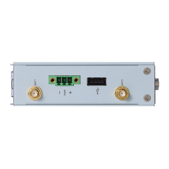
Page 20: I/O Outlets
IFB112 User’s Manual I/O Outlets The following figures show you I/O outlets on front view and bottom view of the IFB112. Front View Top View Bottom View Introduction... -
Page 21: Packing List
IFB112 User’s Manual Packing List The package bundled with your IFB112 should contain the following items: IFB112 System Unit x 1 Din-rail Kit x 1 Power terminal block x 1 DIO terminal block x 1 ... - Page 22 IFB112 User’s Manual This page is intentionally left blank. Introduction...
-
Page 23: Chapter 2 Hardware Installation
CHAPTER 2 HARDWARE INSTALLATION Installing Din-rail Mounting The IFB112 provides Din-rail Mount that customers can install as below: Prepare DIN Mount assembling components (screws and bracket) ready. Installing Wall Mounting (Opitonal) The IFB112 provides Wall Mounting that customers can install as below: Prepare Wall Mount assembling components (screws and bracket) ready. - Page 24 IFB112 User’s Manual This page is intentionally left blank. Hardware Installation...
Need help?
Do you have a question about the IFB112 and is the answer not in the manual?
Questions and answers