Sign In
Upload
Download
Table of Contents
Contents
Add to my manuals
Delete from my manuals
Share
URL of this page:
HTML Link:
Bookmark this page
Add
Manual will be automatically added to "My Manuals"
Print this page
×
Bookmark added
×
Added to my manuals
Manuals
Brands
Advantech Manuals
Touch Panel
PPC-3150
User manual
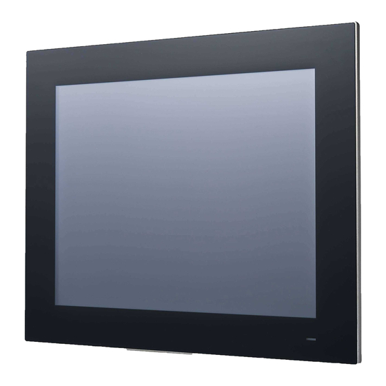
Advantech PPC-3150 User Manual
15"/17"/19" color tft lcd panel pc with intel atom e3845 processor
Hide thumbs
Also See for PPC-3150
:
User manual
(76 pages)
1
2
3
4
5
6
Table Of Contents
7
8
9
10
11
12
13
14
15
16
17
18
19
20
21
22
23
24
25
26
27
28
29
30
31
32
33
34
35
36
37
38
39
40
41
42
43
44
45
46
47
48
49
50
51
52
53
54
55
56
57
58
59
60
61
62
63
64
65
66
67
68
69
70
71
72
73
74
75
76
77
78
79
80
page
of
80
Go
/
80
Contents
Table of Contents
Bookmarks
Table of Contents
Table of Contents
Chapter 1 General Information
Introduction
Specifications
Specifications Comparison
General
Power Specifications
Environmental Specifications
Certification Specifications
IP Rating
Power Consumption Test Conditions
Dimensions
Chapter 2 System Installation & Setup
Quick Installation Guide
Installation Procedures
Connecting the Power Cable
Connecting the Keyboard and Mouse
Memory Card Installation
HDD Installation
Mini SATA Installation
Wireless LAN Card Installation
Riser Card Installation
AT/ATX Function Switch
Mount Bracket Installation
Optional Module Installation
Chapter 3 Jumper Settings
Jumpers and Connectors
External COM Ports and Pin Definitions
Chapter 4 Software Setup
Driver Installation
BIOS Setup Utility
Update BIOS
Entering the BIOS Setup Utility
LCD Brightness Adjustment
COM3 Mode Selection (RS422/RS485)
COM3 RS485 Terminal Selection
Wake on LAN
AT & ATX Setup
OS Selection
SATA Mode Selection
Boot Options
Pci/Pci-E
Appendix A PCI/PCI-E
Pci/Pci-E
Advertisement
Quick Links
1
Boot Options
Download this manual
User Manual
PPC-3150/3170/3190
15"/17"/19" Color TFT LCD panel
PC with Intel® Atom™ E3845
Processor
Table of
Contents
Previous
Page
Next
Page
1
2
3
4
5
Advertisement
Table of Contents
Need help?
Do you have a question about the PPC-3150 and is the answer not in the manual?
Ask a question
Questions and answers
Related Manuals for Advantech PPC-3150
Touch Panel Advantech PPC-3150 User Manual
Intel atom e3845 processor based panel pc, with 15"/17" color tft lcd display (76 pages)
Touch Panel Advantech PPC-3100S User Manual
Intel celeron n2930 panel pc with 10.4''/12.1''/15'' color tft lcd display (68 pages)
Touch Panel Advantech PPC-3210SW User Manual
Intel celeron n2930 panel pc with 10.4''/12.1''/15''/21.5" color tft lcd display (68 pages)
Touch Panel Advantech PPC-3151SW User Manual
Intel core i processor based panel pc with 15.6"/18.5"/21.5"/23.8" color tft lcd display (62 pages)
Touch Panel Advantech PPC-3211SW User Manual
Intel core i processor based panel pc with 21.5"/18.5"/15.6" color tft lcd display (60 pages)
Touch Panel Advantech PPC-3211SW Startup Manual
21.5”/18.5”/15.6” panel pc with tft lcd and 6th gen intel coretm series processor (13 pages)
Touch Panel Advantech PPC-3211SW Startup Manual
Panel pc with tft lcd and 6th/7th gen intel coretm processor (13 pages)
Touch Panel Advantech PPC-3151W Startup Manual
15.6”/21.5” panel pc with tft lcd and 7th gen intel core series processor (15 pages)
Touch Panel Advantech PPC-3151W User Manual
15.6”/21.5” panel pc with tft lcd and intel core i processor (66 pages)
Touch Panel Advantech PPC-3150SW Startup Manual
(12 pages)
Touch Panel Advantech PPC-3150SW User Manual
15.6"/18.5"/23.8" panel pc with tft lcd and intel pentium n4200 processor (54 pages)
Touch Panel Advantech PPC-3150-XE4BE Startup Manual
15/17/19” panel pc with tft lcd and intel atom e3845 processor (17 pages)
Touch Panel Advantech PPC-315W TGL Startup Manual
15.6''/21.5” panel pc with tft led and 11th gen intel core tm processor (15 pages)
Touch Panel Advantech PPC-315W TGL User Manual
15.6"/21.5" panel pc with tft led and 11th gen intel core i processor (50 pages)
Touch Panel Advantech PPC-321W TGL User Manual
15.6"/18.5"/21.5"/23.8" panel pc with tft led and 11th gen intel core i processor (56 pages)
Touch Panel Advantech PPC-315SW Startup Manual
Adl_n 15.6”/18.5”/21.5” fanless widescreen panel pc with intel n97 quad-core processor (13 pages)
This manual is also suitable for:
Ppc-3170
Ppc-3190
Table of Contents
Print
Rename the bookmark
Delete bookmark?
Delete from my manuals?
Login
Sign In
OR
Sign in with Facebook
Sign in with Google
Upload manual
Upload from disk
Upload from URL


Need help?
Do you have a question about the PPC-3150 and is the answer not in the manual?
Questions and answers