Advantech PPC-3211SW User Manual
Intel core i processor based panel pc with 21.5"/18.5"/15.6" color tft lcd display
Hide thumbs
Also See for PPC-3211SW:
- Startup manual (13 pages) ,
- Startup manual (13 pages) ,
- User manual (62 pages)

Related Manuals for Advantech PPC-3211SW


Summary of Contents for Advantech PPC-3211SW
- Page 1 User Manual PPC-3211SW/3181SW/ 3151SW Intel® Core™ i processor based Panel PC with 21.5"/18.5"/15.6" Color TFT LCD Display...
- Page 2 No part of this manual may be reproduced, copied, translated, or transmitted in any form or by any means without the prior written permission of Advantech Co., Ltd. The information provided in this manual is intended to be accurate and reliable.
-
Page 3: Declaration Of Conformity
(ESD) or electromagnetic interference (EMI) leakage, we strongly recommend using CE-compliant industrial enclosure products. Technical Support and Assistance Visit the Advantech website at http://support.advantech.com to obtain the latest product information. Contact your distributor, sales representative, or Advantech's customer service center for technical support if you need additional assistance. Please have the following information to hand before calling: –... -
Page 4: Safety Instructions
In compliance with IEC 704-1:1982 specifications, the sound pressure level at the operator’s position does not exceed 70 dB (A). DISCLAIMER: These instructions are provided according to IEC 704-1. Advantech disclaims all responsibility for the accuracy of any statements contained herein. - Page 5 Par exemple, “Si la batterie est remplacée par un modèle inapproprié, il y a un risque d’explosion. Remplacer les produits identiques ou équiva- lents recommandés par le fabricant. Traitement des piles usagées selon les instructions du fabricant.” Note! Notes provide additional optional information. v PPC-3211SW/3181SW/3151SW User Manual...
- Page 6 Revision Date Version Description/Change July 2018 Initial PPC-3151SW Jun 2019 PPC-3211SW/3181SW/3151SW User Manual...
-
Page 7: Table Of Contents
Figure 1.2 rear panel ..............3 Panel Underside..................3 Figure 1.3 Panel PC underside............ 3 Dimensions ....................4 Figure 1.4 PPC-3211SW dimensions .......... 4 Figure 1.5 PPC-3181SW dimensions .......... 4 Figure 1.6 PPC-3151SW dimensions .......... 4 Specifications .................... 5 Ordering Information ................. 6... - Page 8 Boot Options ................42 4.2.8 TPM Setup.................. 43 Appendix A BSMI RoHS ........45 BSMI RoHS..................... 46 Appendix B China RoHS ........47 China RoHS .................... 48 Appendix C Watchdog Program Example ... 49 Watchdog Program Example ..............50 PPC-3211SW/3181SW/3151SW User Manual viii...
-
Page 9: Chapter 1 General Information
Chapter General Information This chapter provides general information regarding PPC- 3211SW/3181SW/3151SW. Introduction Specifications Dimensions... -
Page 10: Introduction
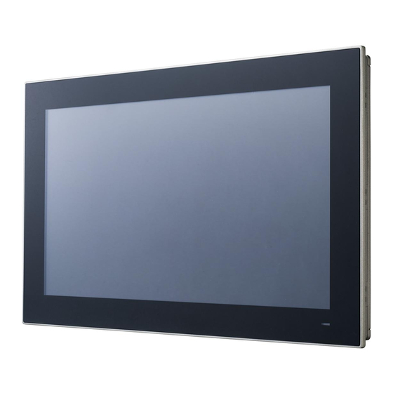
Optional mini PCIe 802.11b/g/n wireless module Front Panel The PPC-3211SW/3181SW/3151SW front panel is a true-flat color TFT LCD touch- screen with Projected Capacitive Multi-Touch. The front panel is IP65 rated for dust and water tolerance (Figure 1.1). Touch Screen... -
Page 11: Rear Panel
Rear Panel The PPC-3211SW/3181SW/3151SW rear panel features four VESA mount (100 x 100 mm) holes located below figure 1.2. Figure 1.2 rear panel Panel Underside The system I/O located at the panel underside (Figures 1.3) are listed below. 1 x Power input connector ... -
Page 12: Dimensions
Dimensions 558.40 Figure 1.4 PPC-3211SW dimensions 477.7 Figure 1.5 PPC-3181SW dimensions Figure 1.6 PPC-3151SW dimensions PPC-3211SW/3181SW/3151SW User Manual... -
Page 13: Specifications
HDD (HDD test condition: the SPEC of HDD Storage Tempera- -20 ~ 60 °C (-4 ~ 140 °F) ture Relative Humidity 10 ~ 95% @ 40°C (non-condensing) Operating 10 G Peak Acceleration (11 ms Duration), Follows IEC Shock 60068-2-27 5 PPC-3211SW/3181SW/3151SW User Manual... -
Page 14: Ordering Information
Panel PC with Intel® 6th Core i proces- PPC-3181SW-P65A PPC-3151SW-P65A Power adapter 100 ~ 240 V , 90 W, 96PSA-A90W19OT-3 PPC-WLAN-C1E Wi-Fi module with antenna PPC-ARM-A03 Arm mount VESA standard PPC-174T-WL-MTE Wall mount kit PPC-Stand-A1E Stand kit PPC-3211SW/3181SW/3151SW User Manual... -
Page 15: Chapter 2 System Installation And Setup
Chapter System Installation and Setup Quick System Tour Memory Card Installation HDD Installation mSATA Installation Wireless LAN Card Installation TPM installation Mounting the System... -
Page 16: Quick System Tour
Before setting up the panel PC, take a moment to identify the locations of the device- controls, drives, connectors, and ports (as shown in Figure 2.3). When placed upright, the PPC-3211SW/3181SW/3151SW front panel should appear as shown in Figure 2.1. Since PPC-3211SW/3181SW/3151SW are series models, the following photos in the manual are PPC-3211SW examples. -
Page 17: Installation Procedures
Configure the system 2.2.1 Memory Card Installation Remove four screws shown in red circle, then remove the six screws shown in the green circle and finally remove the rear cover. Figure 2.4 Retention screws on rear cover 9 PPC-3211SW/3181SW/3151SW User Manual... - Page 18 Assurez-vous que le tampon thermique (fourni dans la boîte d'acces- soires) est placé sur la carte mémoire, comme illustré à la Figure 2.6. Note! The second disassembly and assembly needs to replace the CPU ther- mal pad. PPC-3211SW/3181SW/3151SW User Manual...
-
Page 19: Hdd Installation
Figure 2.7 Retention screws on HDD bracket Figure 2.8 HDD module bracket Connect the SATA cable provided in the accessory box to the SATA HDD mod- ule (Figure 2.9). Figure 2.9 SATA cable connected to SATA HDD 11 PPC-3211SW/3181SW/3151SW User Manual... -
Page 20: Msata Installation
Figure 2.11 SATA HDD connected to the mainboard 2.2.3 mSATA Installation Insert the mSATA card into the socket. Secure the card in place using two screws provided in the accessory box (Figure 2.12). Figure 2.12 mSATA module installation PPC-3211SW/3181SW/3151SW User Manual... -
Page 21: Wireless Lan Card Installation
If a half-size PCIe is used, then use the hexagonal screws provided in the accessory box. Screws in red circles should be tightened, See Fig 2.13 Note! Note! For wireless LAN card module, you can choose Advantech Product: (Part No. PPC-WLAN-C1E). Retrieve the hexagonal screw provided in the accessory box. -
Page 22: Figure 2.15Full-Size Mini Pcie Lan Antenna Cables
Figure 2.15 Full-size mini PCIe LAN antenna cables Remove the two plugs located at the top of the rear cover. Figure 2.16 Removing plugs for the antennae Install the external antennas. Figure 2.17 Location of external antennae PPC-3211SW/3181SW/3151SW User Manual... -
Page 23: Installing Tpm
2. Insert the cable into the TPM interface. Note that the white point corresponds to the first pin of the TPM board. Add the TPM cable which needs cross under the SATA cable. Figure 2.19 Assemble TPM Cable 15 PPC-3211SW/3181SW/3151SW User Manual... -
Page 24: Mounting The System
Secure the mount plate to the wall by inserting screws into the two pilot holes and tightening them. Figure 2.20 Wall mount plate Insert four M4 screws into the holes on the panel PC and tighten them to secure the bracket to the rear panel. PPC-3211SW/3181SW/3151SW User Manual... -
Page 25: Figure 2.21Screw Locations On The Rear Panel
PC with the wall mount plate on the wall and slide the panel PC down- wards to hang the bracket on the mount plate. Figure 2.22 Mounting the panel PC on a wall Secure the panel PC in place by tightening screws in the wall mount bracket. 17 PPC-3211SW/3181SW/3151SW User Manual... -
Page 26: Panel Mounting
Prepare a panel cutout according to the Panel PC dimensions. Panel cutout dimensions: PPC-3211SW: 550.3 x 341.8 mm (21.66 x 13.45 in) PPC-3181SW: 479.3 x 300.3 mm (18.87 x 11.82 in) PPC-3151SW: 413 x 262 mm (16.25 x 10.31 in) Install the panel PC in the cabinet and retrieve eight hook brackets from the accessory box. -
Page 27: Figure 2.25Hook Brackets Location
Figure 2.25 Hook brackets location Tighten the screws to affix the panel PC in place (Figure 2.26). Figure 2.26 Fasten the hook bracket Figure 2.27 Panel mount rear view 19 PPC-3211SW/3181SW/3151SW User Manual... -
Page 28: Arm Mounting
2.4.3 Arm Mounting PPC-3211SW/3181SW/3151SW can be mounted on a VESA-compliant arm mount with a 100 mm interface pad. To affix the panel PC to an arm mount, follow the steps below. Refer to the installation instruction of the mounting arm to correctly mount the arm onto the surface as a base. -
Page 29: Stand Mounting
To mount the panel PC onto the stand, follow the steps below Use four M4 x 8L screws to affix the VESA bracket to the panel PC. Users can choose 100 x 100 mm VESA mount according to their requirements. Figure 2.29 VESA mount screw holes 21 PPC-3211SW/3181SW/3151SW User Manual... -
Page 30: Figure 2.30Securing The Vesa Mount Base
Use the four M4 x 8L screws to secure the base plate to the mount stand. Figure 2.30 Securing the VESA mount base Use four M4 x 6L screws to secure the mount stand to the VESA mount bracket. Figure 2.31 Securing the VESA mount bracket PPC-3211SW/3181SW/3151SW User Manual... -
Page 31: Figure 2.32Securing The Stand Mount Hinge Cover
Use one M4 x 5L screw to secure the stand mount hinge cover. Figure 2.32 Securing the stand mount hinge cover Figure 2.33 Completed stand mount 23 PPC-3211SW/3181SW/3151SW User Manual... - Page 32 PPC-3211SW/3181SW/3151SW User Manual...
-
Page 33: Jumper Settings
Chapter Jumper Settings Motherboard Layout Jumpers and Connectors External COM Ports and Pin Definitions... -
Page 34: Motherboard Layout
A diagram of the motherboard layout showing the locations of the internal peripheral connectors is provided below (Figure 3.1). The internal peripheral connectors are accessible when the motherboard is outside of the chassis. Figure 3.1 Motherboard layout diagram PPC-3211SW/3181SW/3151SW User Manual... -
Page 35: Internal Jumpers And Connectors
Panel ID Select Switch 2x4P 3.2.1 Touch Power Select Icon Resistance Touch Power Select open Touch Disable closed Touch Enable Default* 3.2.2 LVDS PWM Power Select Jumper Icon LVDS PWM Power Select Jumper (1-2) (2-3) 3.3V Default* 27 PPC-3211SW/3181SW/3151SW User Manual... -
Page 36: Lvds Enable Power Select Jumper
RTC Select Icon RTC Select (1-2) Normal Default* (2-3) Clear CMOS 3.2.5 COM1 Pin 9 Power Select CN42 Icon COM1 Pin 9 Power Select (1-2) COM1 RI Default* (2-3) COM1 Pin 9 5V (4-5) COM1 Pin 9 12V PPC-3211SW/3181SW/3151SW User Manual... -
Page 37: Atx/At Select
Model Number 1110 1920 x 1080 (48-bit) PPC-3211SW 0111 1366 x 768 (24-bit) PPC-3181SW 1100 1920 x 1080 (48-bit) PPC-3151SW Figure 3.2 External COM Ports and Pin Definitions Figure 3.3 Location of COM1 and COM2 ports 29 PPC-3211SW/3181SW/3151SW User Manual... - Page 38 COM1 Pin 9 is set as “RI” by default. This setting can be changed to 5 V or 12 V out- put using a jumper. COM2: RS-232/422/485 Note! COM2 does not support ring function. COM1 COM2 RS-232 RS-232 RS-422 RS-485 DATA- DATA+ Ring or 5V/12V output RING PPC-3211SW/3181SW/3151SW User Manual...
-
Page 39: Software Setup
Chapter Software Setup Driver Installation BIOS Setup Program... -
Page 40: Driver Installation
Driver Installation Before installing software on the panel PC, install the corresponding drivers to ensure full functionality. All drivers can be downloaded from the Advantech website http://www.advantech.com BIOS Setup Program 4.2.1 Entering BIOS Setup After powering on the system, press the <Del> button to access the BIOS Setup screen. -
Page 41: Adjustment Of Lcd Brightness
4.2.2 Adjustment of LCD Brightness Select System Agent (SA) Configuration option in the Chipset tab. Select Graphics Configuration option in the Chipset tab. 33 PPC-3211SW/3181SW/3151SW User Manual... - Page 42 Select LCD Control option to choose between six brightness levels. Select Brightness Mode Control and select SIO. PPC-3211SW/3181SW/3151SW User Manual...
- Page 43 Select Brightness Control to choose between five brightness levels. Brightness is controlled through Power Options in Windows OS. 35 PPC-3211SW/3181SW/3151SW User Manual...
-
Page 44: Com2 Mode Selection (Rs232/Rs422/Rs485)
4.2.3 COM2 Mode Selection (RS232/RS422/RS485) Select NCT5523D Super IO Configuration in the Advanced tab. Select Serial Port 2 Configuration option. PPC-3211SW/3181SW/3151SW User Manual... - Page 45 Select Serial Port 2 Mode option to set the COM2 operation mode as RS232, RS422, or RS485. If COM2 mode is set as RS485, the RS485 Auto Flow control option can be Enabled or Disabled. 37 PPC-3211SW/3181SW/3151SW User Manual...
-
Page 46: Bios At And Atx Setup
If COM2 mode is set as RS485, the Serial Port2 Terminal option can be Enabled or Disabled. 4.2.4 BIOS AT and ATX Setup Select PCH-IO Configuration option in the Chipset tab. PPC-3211SW/3181SW/3151SW User Manual... -
Page 47: Wake-On-Lan
Select Restore AC Power Loss and set the Power On option to AT and the Power Off option to ATX. 4.2.5 Wake-on-LAN Select PCH-IO Configuration option in the Chipset tab. 39 PPC-3211SW/3181SW/3151SW User Manual... - Page 48 Set the Wake On By PCIE Wake(I211/Ring) option to Enabled for LAN2 & COM Ring. 3. Set the Wake on By LAN1(219LM) option to Enabled. PPC-3211SW/3181SW/3151SW User Manual...
-
Page 49: Sata Mode Selection
4.2.6 SATA Mode Selection Select SATA Configuration option in the Advanced tab. Select SATA Mode Selection to adjust the settings. 41 PPC-3211SW/3181SW/3151SW User Manual... -
Page 50: Boot Options
4.2.7 Boot Options Select CSM Configuration option in the Advanced tab. Select Boot Option Filter to adjust the settings. PPC-3211SW/3181SW/3151SW User Manual... -
Page 51: Tpm Setup
4.2.8 TPM Setup 1. Select Trusted Computing option in the Advanced tab. 2. Set the Security Device Support option to Enabled. 3. Restart after saving. 43 PPC-3211SW/3181SW/3151SW User Manual... - Page 52 PPC-3211SW/3181SW/3151SW User Manual...
-
Page 53: Bsmi Rohs
Appendix BSMI RoHS... -
Page 54: Bsmi Rohs
BSMI RoHS 設備名稱:電腦 型號 (型式) :PPC-3211SW/3181SW/3151SW Equipment name Type designation (Type) 限用物質及其化學符號 Restricted substances and its chemical symbols 多溴聯苯 六價鉻 多溴二苯醚 單元 Unit Polybromina 鎘 Hexavalent Polybrominate 鉛 Lead 汞 Mercury Cadmium chromium d diphenyl (Pb) (Hg) (Cd) biphenyls ethers (PBDE) (PBB) 液晶面板... -
Page 55: Appendix B China Rohs
Appendix China RoHS... -
Page 56: China Rohs
China RoHS Thank you for choosing an Advantech product. In compliance with the China RoHS standard SJ/T11364, “Marking for the Restriction of the Use of Hazardous Sub- stances in Electrical and Electronic Products”, all hazardous substances present in the product are disclosed below. -
Page 57: Appendix C Watchdog Program Example
Appendix Watchdog Program Example... -
Page 58: Watchdog Program Example
OUT DX, AL MOV DX, 2FH MOV AL, 00H; bit 0: 0 = pulse mode, 1 = level mode; bit 3: 0 = second mode, 1 = minute mode OUT DX, AL; set second mode, default value PPC-3211SW/3181SW/3151SW User Manual... - Page 59 OUT DX, AL MOV DX, 2FH MOV AL, 05H OUT DX, AL; set timeout value as 5s; 00 = timeout disabled ;----------------------------------------------- ; Exit the Extended Function Mode ;---------------------------------------------- MOV DX, 2EH MOV AL, AAH OUT DX, AL 51 PPC-3211SW/3181SW/3151SW User Manual...
- Page 60 No part of this publication may be reproduced in any form or by any means, such as electronically, by photocopying, recording, or otherwise, without prior written permission from the publisher. All brand and product names are trademarks or registered trademarks of their respective companies. © Advantech Co., Ltd. 2018...
Need help?
Do you have a question about the PPC-3211SW and is the answer not in the manual?
Questions and answers